Page 1186 of 3189
AEC640
Overall Function Check
SEF111X
SEC163BA
MEC475B
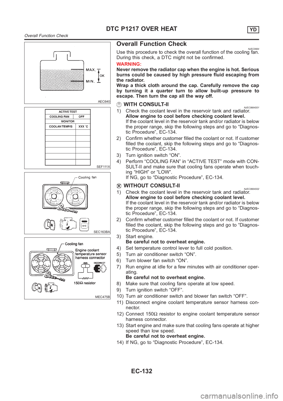
NJEC0664Use this procedure to check the overall function of the cooling fan.
During this check, a DTC might not be confirmed.
WARNING:
Never remove the radiator cap when the engine is hot. Serious
burns could be caused by high pressure fluid escaping from
the radiator.
Wrap a thick cloth around the cap. Carefully remove the cap
by turning it a quarter turn to allow built-up pressure to
escape. Then turn the cap all the way off.
WITH CONSULT-IINJEC0664S011) Check the coolant level in the reservoir tank and radiator.
Allow engine to cool before checking coolant level.
If the coolant level in the reservoir tank and/or radiator is below
the proper range, skip the following steps and go to “Diagnos-
tic Procedure”, EC-134.
2) Confirm whether customer filled the coolant or not. If customer
filled the coolant, skip the following steps and go to “Diagnos-
tic Procedure”, EC-134.
3) Turn ignition switch “ON”.
4) Perform “COOLING FAN” in “ACTIVE TEST” mode with CON-
SULT-II and make sure that cooling fans operate when touch-
ing “HIGH” or “LOW”.
If NG, go to “Diagnostic Procedure”, EC-134.
WITHOUT CONSULT-IINJEC0664S021) Check the coolant level in the reservoir tank and radiator.
Allow engine to cool before checking coolant level.
If the coolant level in the reservoir tank and/or radiator is below
the proper range, skip the following steps and go to “Diagnos-
tic Procedure”, EC-134.
2) Confirm whether customer filled the coolant or not. If customer
filled the coolant, skip the following steps and go to “Diagnos-
tic Procedure”, EC-134.
3) Start engine.
Be careful not to overheat engine.
4) Set temperature control lever to full cold position.
5) Turn air conditioner switch “ON”.
6) Turn blower fan switch “ON”.
7) Run engine at idle for a few minutes with air conditioner oper-
ating.
Be careful not to overheat engine.
8) Make sure that cooling fans operate at low speed.
9) Turn ignition switch “OFF”.
10) Turn air conditioner switch and blower fan switch “OFF”.
11) Disconnect engine coolant temperature sensor harness con-
nector.
12) Connect 150Ωresistor to engine coolant temperature sensor
harness connector.
13) Start engine and make sure that cooling fans operate at higher
speed than low speed.
Be careful not to overheat engine.
14) If NG, go to “Diagnostic Procedure”, EC-134.
DTC P1217 OVER HEATYD
Overall Function Check
EC-132
Page 1198 of 3189
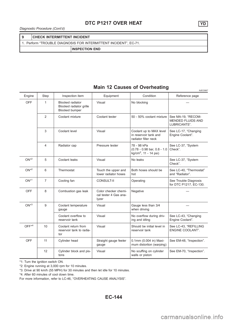
9 CHECK INTERMITTENT INCIDENT
1. Perform “TROUBLE DIAGNOSIS FOR INTERMITTENT INCIDENT”, EC-71.
INSPECTION END
Main 12 Causes of OverheatingNJEC0667
Engine Step Inspection item Equipment Condition Reference page
OFF 1 Blocked radiator
Blocked radiator grille
Blocked bumperVisual No blocking —
2 Coolant mixture Coolant tester 50 - 50% coolant mixture See MA-19, “RECOM-
MENDED FLUIDS AND
LUBRICANTS”.
3 Coolant level Visual Coolant up to MAX level
in reservoir tank and
radiator filler neckSee LC-17, “Changing
Engine Coolant”.
4 Radiator cap Pressure tester 78 - 98 kPa
(0.78 - 0.98 bar, 0.8 - 1.0
kg/cm
2, 11 - 14 psi)See LC-37, “System
Check”.
ON*
25 Coolant leaks Visual No leaks See LC-37, “System
Check”.
ON*
26 Thermostat Touch the upper and
lower radiator hosesBoth hoses should be
hotSee LC-40, “Thermostat”
and “Radiator”.
ON*
17 Cooling fan CONSULT-II Operating See Trouble Diagnosis
for DTC P1217, EC-130.
OFF 8 Combustion gas leak Color checker chemi-
cal tester 4 Gas ana-
lyzerNegative —
ON*
39 Coolant temperature
gaugeVisual Gauge less than 3/4
when driving—
Coolant overflow to
reservoir tankVisual No overflow during driv-
ing and idlingSee LC-43, “Changing
Engine Coolant”.
OFF*
410 Coolant return from
reservoir tank to radia-
torVisual Should be initial level in
reservoir tankSee LC-43, “REFILLING
ENGINE COOLANT”.
OFF 11 Cylinder head Straight gauge feeler
gauge0.1mm (0.004 in) Maxi-
mum distortion (warping)See EM-48, “Inspection”.
12 Cylinder block and pis-
tonsVisual No scuffing on cylinder
walls or pistonSee EM-70, “Inspection”.
*1: Turn the ignition switch ON.
*2: Engine running at 3,000 rpm for 10 minutes.
*3: Drive at 90 km/h (55 MPH) for 30 minutes and then let idle for 10 minutes.
*4: After 60 minutes of cool down time.
For more information, refer to LC-46, “OVERHEATING CAUSE ANALYSIS”.
DTC P1217 OVER HEATYD
Diagnostic Procedure (Cont’d)
EC-144
Page 1298 of 3189
SBR820BA
PrecautionsNJCL0001Recommended fluid is brake fluid “DOT 3” or “DOT 4”
(Europe). Refer to MA-19, “Fluid and Lubricants”.
Never reuse drained brake fluid.
Be careful not to splash brake fluid on painted areas.
When removing and installing clutch piping, use Tool.
Use new brake fluid to clean or wash all parts of master
cylinder and operating cylinder.
Never use mineral oils such as gasoline or kerosene. It will
ruin the rubber parts of the hydraulic system.
WARNING:
After cleaning clutch disc, wipe it with a dust collector. Do not
use compressed air.
PRECAUTIONS
Precautions
CL-2
Page 1306 of 3189
CLUTCH PEDAL ADJUSTMENTNJCL0006S04Pedal StrokeNJCL0006S04011. Loosen the pedal stopper bolt completely (so there is no con-
tact between pedal and stopper bolt).
2. Adjust pedal stroke to the specified value with the master cyl-
inder push rod.
3. Adjust the pedal stopper bolt until it is just in contact with the
pedal, then tighten the lock nut.
4. Once stroke is set to specification, adjust clutch pedal free
play.
Pedal stroke “S”.
Refer to “SDS”, CL-24.
Pedal Free PlayNJCL0006S04021. Adjust pedal free play to the specified value with the master
cylinder push rod.
2. Tighten lock nut of the master cylinder push rod.
Push on the clutch pedal until resistance is felt, and check the
distance the pedal moves.
Pedal free play “A”.
Refer to “SDS”, CL-24.
SCL838
SCL839
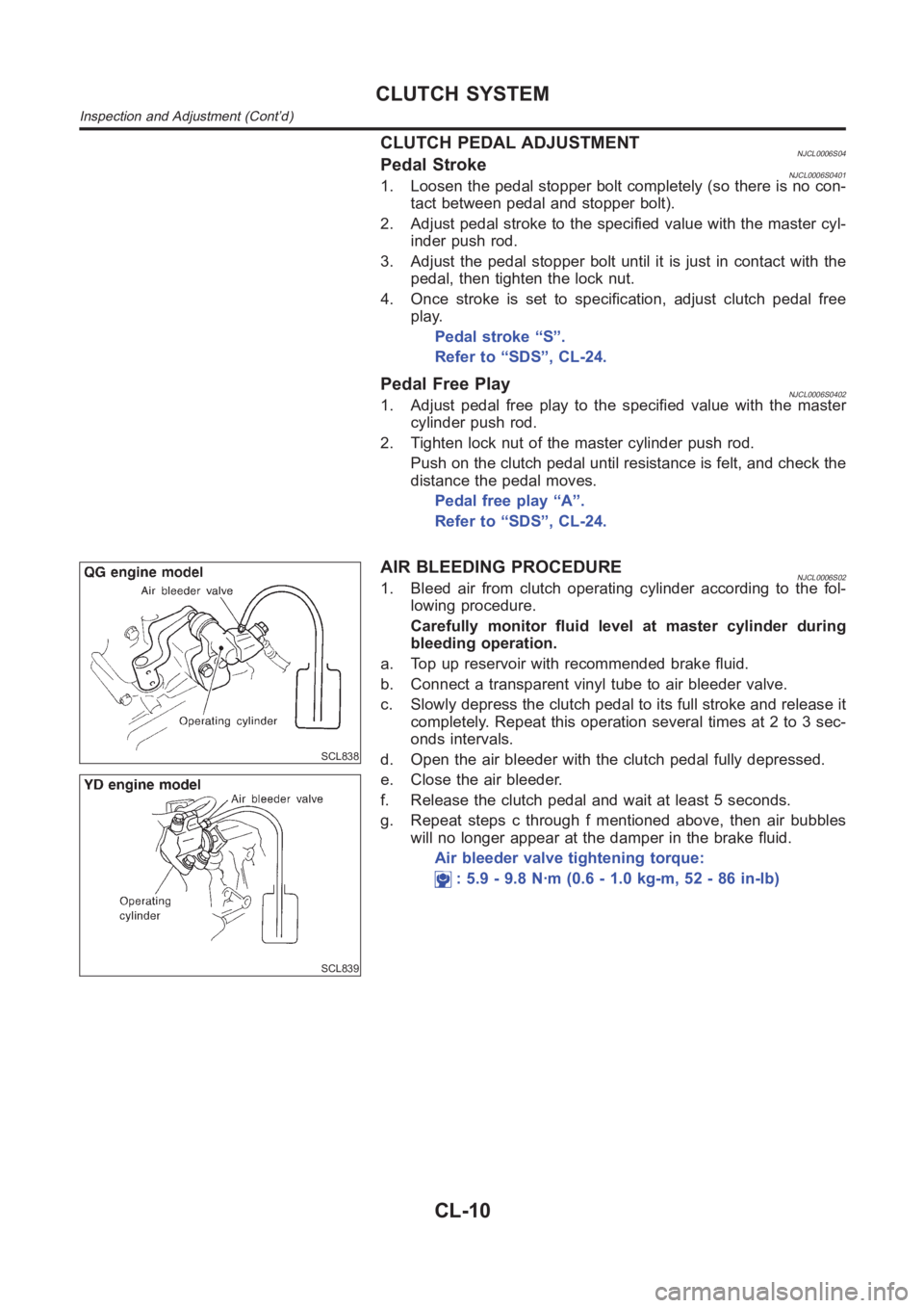
AIR BLEEDING PROCEDURENJCL0006S021. Bleed air from clutch operating cylinder according to the fol-
lowing procedure.
Carefully monitor fluid level at master cylinder during
bleeding operation.
a. Top up reservoir with recommended brake fluid.
b. Connect a transparent vinyl tube to air bleeder valve.
c. Slowly depress the clutch pedal to its full stroke and release it
completely. Repeat this operation several times at 2 to 3 sec-
onds intervals.
d. Open the air bleeder with the clutch pedal fully depressed.
e. Close the air bleeder.
f. Release the clutch pedal and wait at least 5 seconds.
g. Repeat steps c through f mentioned above, then air bubbles
will no longer appear at the damper in the brake fluid.
Air bleeder valve tightening torque:
: 5.9 - 9.8 N·m (0.6 - 1.0 kg-m, 52 - 86 in-lb)
CLUTCH SYSTEM
Inspection and Adjustment (Cont’d)
CL-10
Page 1308 of 3189
RemovalNJCL00081. Drain brake fluid.
CAUTION:
Be careful not to splash brake fluid on painted areas; it may
cause paint damage. If brake fluid is splashed on painted
areas, wash it away with water immediately.
2. Remove clutch tube using a flare nut wrench.
3. Remove snap pin between clutch pedal and push rod, and
remove clevis pin.
4. Unscrew master cylinder assembly mounting nuts and remove
master cylinder assembly from vehicle.
InstallationNJCL00091. Connect clutch tube to master cylinder assembly, and hand-
tighten flare nut.
2. Install master cylinder assembly to vehicle, and tighten mount-
ing nuts to the specified torque.
: 11 - 14 N·m (1.1 - 1.5 kg-m, 8 - 10 ft-lb)
3. Tighten clutch tube flare nut using a flare nut torque wrench.
: 15 - 18 N·m (1.5 - 1.8 kg-m, 11 - 13 ft-lb)
4. After installing clevis pin, install snap pin to connect clutch
pedal to push rod.
5. After finishing the operation, bleed air from clutch piping con-
nector and operating cylinder. (Refer to “Air Bleeding
Procedure”, CL-10.)
SCL725
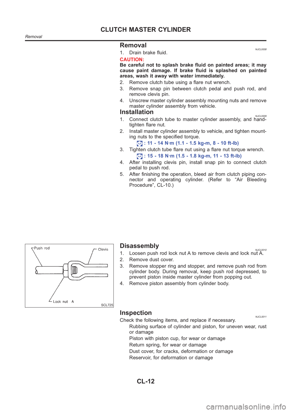
DisassemblyNJCL00101. Loosen push rod lock nut A to remove clevis and lock nut A.
2. Remove dust cover.
3. Remove stopper ring and stopper, and remove push rod from
cylinder body. During removal, keep push rod depressed, to
prevent piston inside master cylinder from popping out.
4. Remove piston assembly from cylinder body.
InspectionNJCL0011Check the following items, and replace if necessary.
Rubbing surface of cylinder and piston, for uneven wear, rust
or damage
Piston with piston cup, for wear or damage
Return spring, for wear or damage
Dust cover, for cracks, deformation or damage
Reservoir, for deformation or damage
CLUTCH MASTER CYLINDER
Removal
CL-12
Page 1310 of 3189
ComponentsNJCL0019
YCL003
RemovalNJCL00201. Drain brake fluid.
CAUTION:
Be careful not to splash brake fluid on painted areas; it may
cause paint damage. If brake fluid is splashed on painted
areas, wash it away with water immediately.
2. Remove union bolt and clutch hose from operating cylinder.
3. Remove operating cylinder mounting bolts, and remove cylin-
der from vehicle.
DisassemblyNJCL0021Remove dust cover, and remove piston assembly from cylinder
body.
InspectionNJCL0022Inspect for following, and replace parts if necessary.
Damage, foreign material, wear, rust, and pinholes on the cyl-
inder inner surface, piston, and sliding part of piston cup
Weak spring
Crack and deformation of dust cover
OPERATING CYLINDER
Components
CL-14
Page 1312 of 3189
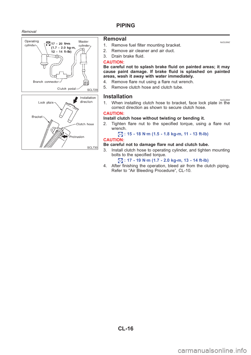
SCL729
RemovalNJCL00421. Remove fuel filter mounting bracket.
2. Remove air cleaner and air duct.
3. Drain brake fluid.
CAUTION:
Be careful not to splash brake fluid on painted areas; it may
cause paint damage. If brake fluid is splashed on painted
areas, wash it away with water immediately.
4. Remove flare nut using a flare nut wrench.
5. Remove clutch hose and clutch tube.
SCL730
InstallationNJCL00431. When installing clutch hose to bracket, face lock plate in the
correct direction as shown to secure clutch hose.
CAUTION:
Install clutch hose without twisting or bending it.
2. Tighten flare nut to the specified torque, using a flare nut
wrench.
: 15 - 18 N·m (1.5 - 1.8 kg-m, 11 - 13 ft-lb)
CAUTION:
Be careful not to damage flare nut and clutch tube.
3. Install clutch hose to operating cylinder, and tighten mounting
bolts to the specified torque.
: 17 - 19 N·m (1.7 - 2.0 kg-m, 13 - 14 ft-lb)
4. After finishing the operation, bleed air from the clutch piping.
Refer to “Air Bleeding Procedure”, CL-10.
PIPING
Removal
CL-16
Page 1334 of 3189
SMA145AA
SMT512C
Changing M/T OilNJMT00861. Drain oil from drain plug and refill with new gear oil.
2. Check oil level.
Oil grade:
API GL-4
Viscosity:
Refer to MA-19, “RECOMMENDED FLUIDS AND
LUBRICANTS”.
Capacity:
RS5F30A 2.8 - 3.0�(4-7/8 - 5-1/4 Imp pt)
RS5F70A 3.0�(5-1/4 Imp pt)
Oil level (Reference data):
RS5F30A 58 - 66 mm (2.28 - 2.60 in)
RS5F70A 75.5 - 80.5 mm (2.969 - 3.166 in)
Drain plug:
: 25 - 34 N·m (2.5 - 3.5 kg-m, 18 - 25 ft-lb)
SMA066C
CheckingNJMT0087OIL LEAK AND OIL LEVELNJMT0087S011. Check that oil is not leaking from transaxle or around it.
2. Check oil level.
Never start engine while checking oil level.
Filler plug:
: 10 - 19 N·m (1.0 - 2.0 kg-m, 87 - 173 in-lb)
M/T OILRS5F30A, RS5F70A
Changing M/T Oil
MT-14