2003 NISSAN ALMERA N16 tow
[x] Cancel search: towPage 1049 of 3189
![NISSAN ALMERA N16 2003 Electronic Repair Manual EVAPORATIVE EMISSION SYSTEM
EC-719
[QG (WITHOUT EURO-OBD)]
C
D
E
F
G
H
I
J
K
L
MA
EC
Component InspectionEBS00KMI
EVAP CANISTER
Check EVAP canister as follows:
1. Block port B . Orally blow air throug NISSAN ALMERA N16 2003 Electronic Repair Manual EVAPORATIVE EMISSION SYSTEM
EC-719
[QG (WITHOUT EURO-OBD)]
C
D
E
F
G
H
I
J
K
L
MA
EC
Component InspectionEBS00KMI
EVAP CANISTER
Check EVAP canister as follows:
1. Block port B . Orally blow air throug](/manual-img/5/57350/w960_57350-1048.png)
EVAPORATIVE EMISSION SYSTEM
EC-719
[QG (WITHOUT EURO-OBD)]
C
D
E
F
G
H
I
J
K
L
MA
EC
Component InspectionEBS00KMI
EVAP CANISTER
Check EVAP canister as follows:
1. Block port B . Orally blow air through port A .
Check that air flows freely through port C .
2. Block port A . Orally blow air through port B .
Check that air flows freely through port C .
FUEL CHECK VALVE
1. Blow air through connector on fuel tank side.
A considerable resistance should be felt and a portion of air flow
should be directed toward the EVAP canister side.
2. Blow air through connector on EVAP canister side.
Air flow should be smoothly directed toward fuel tank side.
3. If fuel check valve is suspected of not properly functioning in
steps 1 and 2 above, replace it.
FUEL TANK VACUUM RELIEF VALVE (BUILT INTO FUEL FILLER CAP)
1. Wipe clean valve housing.
2. Check valve opening pressure and vacuum.
3. If out of specification, replace fuel filler cap as an assembly.
EVAP CANISTER PURGE VOLUME CONTROL SOLENOID VALVE
Refer to EC-676, "Component Inspection" .
PBIB0663E
SEF552Y
SEF989X
Pres-
sure:15.3 - 20.0 kPa (0.153 - 0.200 bar,
0.156 - 0.204 kg/cm
2 , 2.22 - 2.90 psi)
Va c u u m :−6.0 to −3.3 kPa (−0.060 to −0.033 bar,
−0.061 to −0.034 kg/cm
2 , −0.87 to −0.48 psi)
SEF943S
Page 1082 of 3189
JEF360Y
JEF361Y
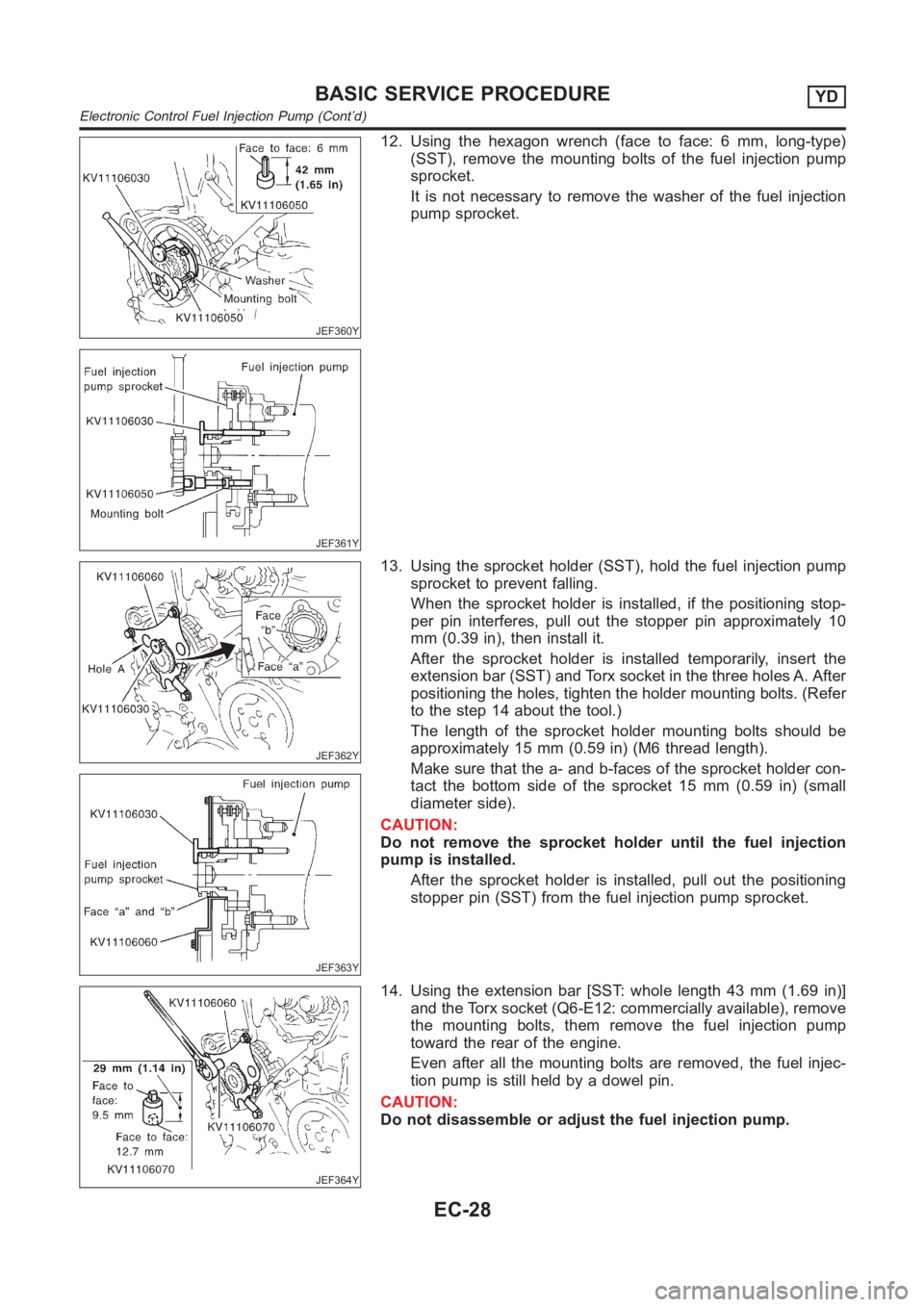
12. Using the hexagon wrench (face to face: 6 mm, long-type)
(SST), remove the mounting bolts of the fuel injection pump
sprocket.
It is not necessary to remove the washer of the fuel injection
pump sprocket.
JEF362Y
JEF363Y
13. Using the sprocket holder (SST), hold the fuel injection pump
sprocket to prevent falling.
When the sprocket holder is installed, if the positioning stop-
per pin interferes, pull out the stopper pin approximately 10
mm (0.39 in), then install it.
After the sprocket holder is installed temporarily, insert the
extension bar (SST) and Torx socket in the three holes A. After
positioning the holes, tighten the holder mounting bolts. (Refer
to the step 14 about the tool.)
The length of the sprocket holder mounting bolts should be
approximately 15 mm (0.59 in) (M6 thread length).
Make sure that the a- and b-faces of the sprocket holder con-
tact the bottom side of the sprocket 15 mm (0.59 in) (small
diameter side).
CAUTION:
Do not remove the sprocket holder until the fuel injection
pump is installed.
After the sprocket holder is installed, pull out the positioning
stopper pin (SST) from the fuel injection pump sprocket.
JEF364Y
14. Using the extension bar [SST: whole length 43 mm (1.69 in)]
and the Torx socket (Q6-E12: commercially available), remove
the mounting bolts, them remove the fuel injection pump
toward the rear of the engine.
Even after all the mounting bolts are removed, the fuel injec-
tion pump is still held by a dowel pin.
CAUTION:
Do not disassemble or adjust the fuel injection pump.
BASIC SERVICE PROCEDUREYD
Electronic Control Fuel Injection Pump (Cont’d)
EC-28
Page 1315 of 3189
SCL738
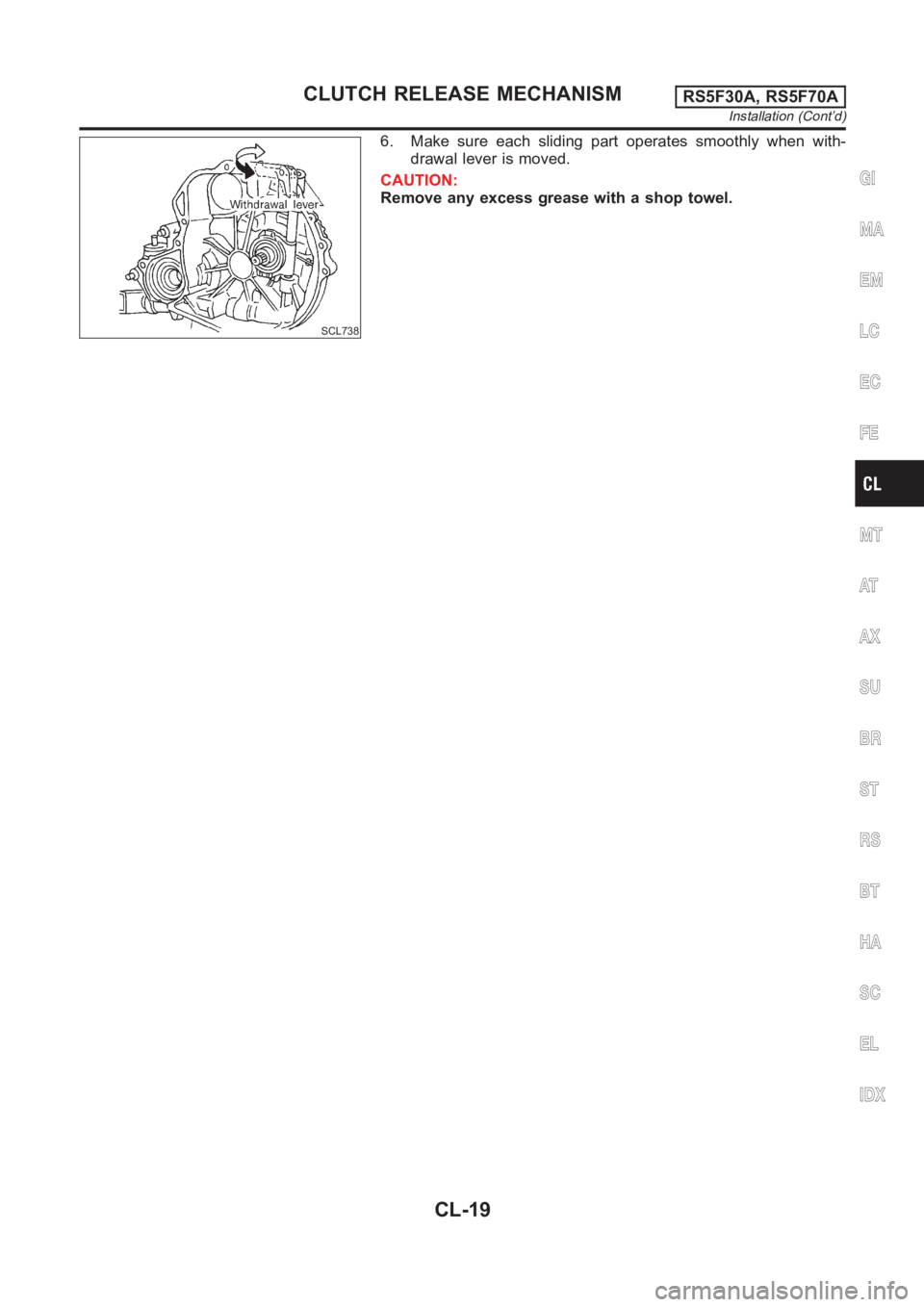
6. Make sure each sliding part operates smoothly when with-
drawal lever is moved.
CAUTION:
Remove any excess grease with a shop towel.
GI
MA
EM
LC
EC
FE
MT
AT
AX
SU
BR
ST
RS
BT
HA
SC
EL
IDX
CLUTCH RELEASE MECHANISMRS5F30A, RS5F70A
Installation (Cont’d)
CL-19
Page 1347 of 3189
SMT940D
SMT951D
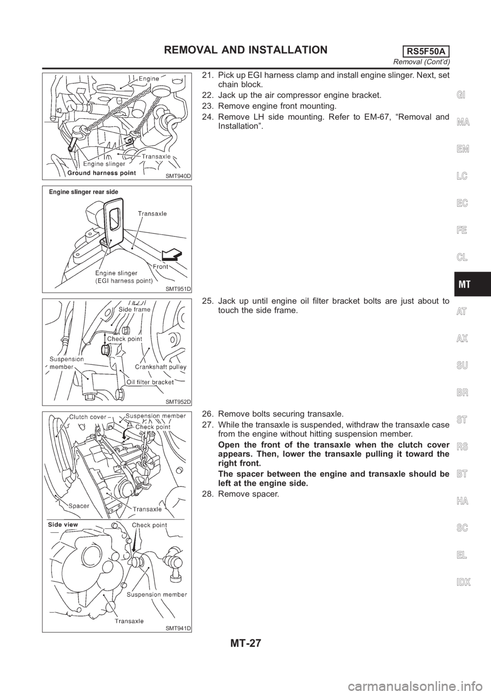
21. Pick up EGI harness clamp and install engine slinger. Next, set
chain block.
22. Jack up the air compressor engine bracket.
23. Remove engine front mounting.
24. Remove LH side mounting. Refer to EM-67, “Removal and
Installation”.
SMT952D
25. Jack up until engine oil filter bracket bolts are just about to
touch the side frame.
SMT941D
26. Remove bolts securing transaxle.
27. While the transaxle is suspended, withdraw the transaxle case
from the engine without hitting suspension member.
Open the front of the transaxle when the clutch cover
appears. Then, lower the transaxle pulling it toward the
right front.
The spacer between the engine and transaxle should be
left at the engine side.
28. Remove spacer.
GI
MA
EM
LC
EC
FE
CL
AT
AX
SU
BR
ST
RS
BT
HA
SC
EL
IDX
REMOVAL AND INSTALLATIONRS5F50A
Removal (Cont’d)
MT-27
Page 1463 of 3189
PRECAUTIONS
AT-7
D
E
F
G
H
I
J
K
L
MA
B
AT
●After performing each TROUBLE DIAGNOSIS, perform
“DTC (Diagnostic Trouble Code) CONFIRMATION PROCE-
DURE”.
The DTC should not be displayed in the “DTC CONFIRMA-
TION PROCEDURE” if the repair is completed.
●Before proceeding with disassembly, thoroughly clean the out-
side of the transaxle. It is important to prevent the internal parts
from becoming contaminated by dirt or other foreign matter.
●Disassembly should be done in a clean work area.
●Use lint-free cloth or towels for wiping parts clean. Common
shop rags can leave fibers that could interfere with the operation
of the transaxle.
●Place disassembled parts in order for easier and proper assembly.
●All parts should be carefully cleaned with a general purpose, non-flammable solvent before inspection or
reassembly.
●Gaskets, seals and O-rings should be replaced any time the transaxle is disassembled.
●It is very important to perform functional tests whenever they are indicated.
●The valve body contains precision parts and requires extreme care when parts are removed and serviced.
Place disassembled valve body parts in order for easier and proper assembly. Care will also prevent
springs and small parts from becoming scattered or lost.
●Properly installed valves, sleeves, plugs, etc. will slide along bores in valve body under their own weight.
●Before assembly, apply a coat of recommended ATF to all parts. Apply petroleum jelly to protect O-rings
and seals, or hold bearings and washers in place during assembly. Do not use grease.
●Extreme care should be taken to avoid damage to O-rings, seals and gaskets when assembling.
●After overhaul, refill the transaxle with new ATF.
●When the A/T drain plug is removed, only some of the fluid is drained. Old A/T fluid will remain in torque
converter and ATF cooling system.
Always follow the procedures under AT-13, "
Changing A/T Fluid" when changing A/T fluid.
Service Notice or PrecautionsECS007N8
FA I L - S A F E
The TCM has an electronic Fail-Safe (limp home mode). This allows the vehicle to be driven even if a major
electrical input/output device circuit is damaged.
Under Fail-Safe, the vehicle always runs in third gear, even with a shift lever position of “1”, “2” or “D”. The cus-
tomer may complain of sluggish or poor acceleration.
When the ignition key is turned “ON” following Fail-Safe operation, O/D OFF indicator lamp blinks for about 8
seconds. Refer to AT- 2 5 0 , "
Diagnostic Procedure Without CONSULT-II" (EXCEPT FOR EURO-OBD) or AT-
51, "TCM SELF-DIAGNOSTIC PROCEDURE (NO TOOLS)" (EURO-OBD).
The blinking of the O/D OFF indicator lamp for about 8 seconds will appear only once and be cleared. The
customer may resume normal driving conditions.
Always follow the “Work Flow”, refer to AT- 2 5 9
(EXCEPT FOR EURO-OBD) or AT- 6 0 (EURO-OBD).
The SELF-DIAGNOSIS results will be as follows:
●The first SELF-DIAGNOSIS will indicate damage to the vehicle speed sensor or the revolution sensor.
●During the next SELF-DIAGNOSIS, performed after checking the sensor, no damages will be indicated.
TORQUE CONVERTER SERVICE
The torque converter should be replaced under any of the following conditions:
●External leaks in the hub weld area.
●Converter hub is scored or damaged.
●Converter pilot is broken, damaged or fits poorly into crankshaft.
●Steel particles are found after flushing the cooler and cooler lines.
●Pump is damaged or steel particles are found in the converter.
●Vehicle has TCC shudder and/or no TCC apply. Replace only after all hydraulic and electrical diagnoses
have been made. (Converter clutch material may be glazed.)
●Converter is contaminated with engine coolant containing antifreeze.
SAT652J
Page 2098 of 3189
ATC-118
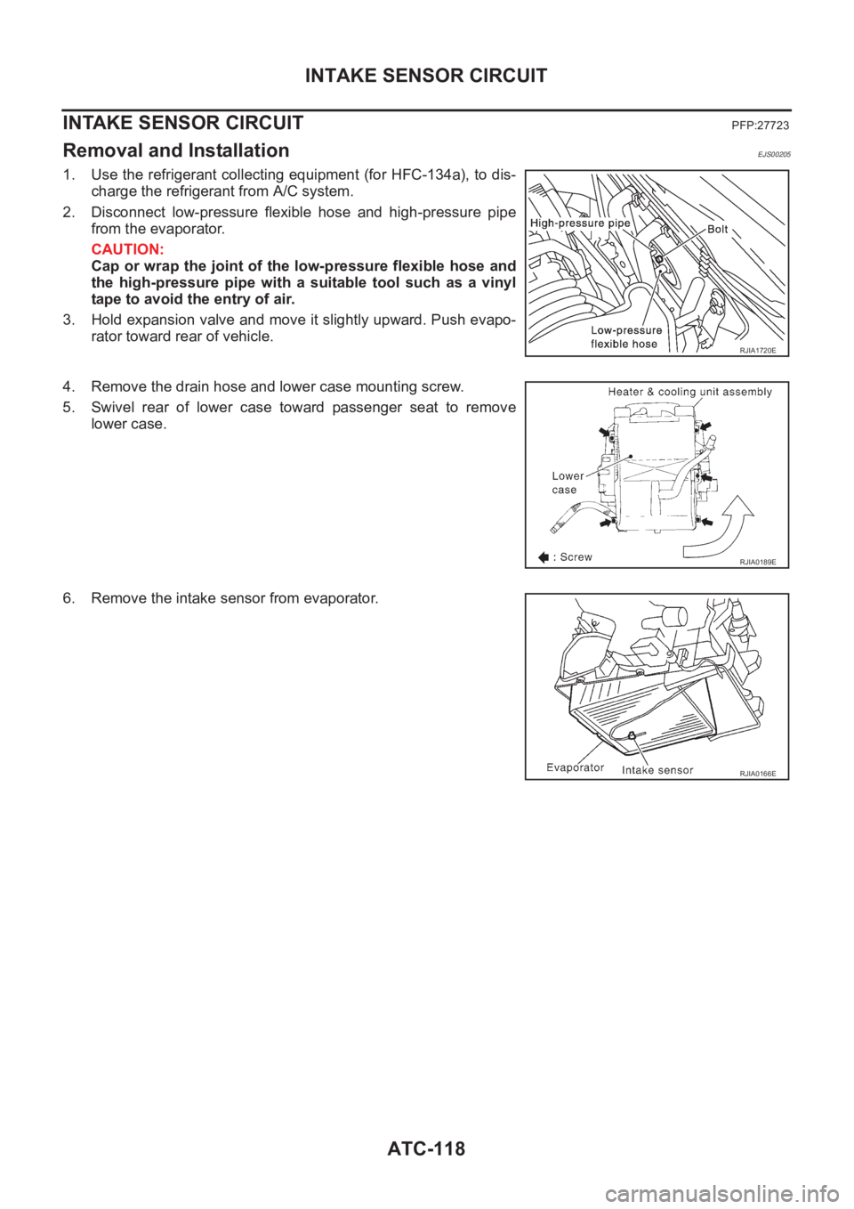
INTAKE SENSOR CIRCUIT
INTAKE SENSOR CIRCUIT
PFP:27723
Removal and InstallationEJS00205
1. Use the refrigerant collecting equipment (for HFC-134a), to dis-
charge the refrigerant from A/C system.
2. Disconnect low-pressure flexible hose and high-pressure pipe
from the evaporator.
CAUTION:
Cap or wrap the joint of the low-pressure flexible hose and
the high-pressure pipe with a suitable tool such as a vinyl
tape to avoid the entry of air.
3. Hold expansion valve and move it slightly upward. Push evapo-
rator toward rear of vehicle.
4. Remove the drain hose and lower case mounting screw.
5. Swivel rear of lower case toward passenger seat to remove
lower case.
6. Remove the intake sensor from evaporator.
RJIA1720E
RJIA0189E
RJIA0166E
Page 2099 of 3189
BLOWER UNIT
ATC-119
C
D
E
F
G
H
I
K
L
MA
B
AT C
BLOWER UNITPFP:27200
Removal and InstallationEJS00206
REMOVAL
1. Remove the glove box assembly.
2. Remove the glove box cover and instrument lower assist panel.
3. Remove the ECM with ECM bracket.
4. Remove the blower unit fixing bolt and screw.
5. Disconnect the blower motor connector, intake door motor con-
nector and auto amp. connector.
6. Remove the harness fixing clip.
7. Move the blower unit downwards.
CAUTION:
Slide the blower unit toward the passenger side, remove loca-
tion pins (2 pieces), then move it downwards.
8. Remove the blower unit.
INSTALLATION
CAUTION:
●Make sure the location pins (2 pieces) are securely installed.
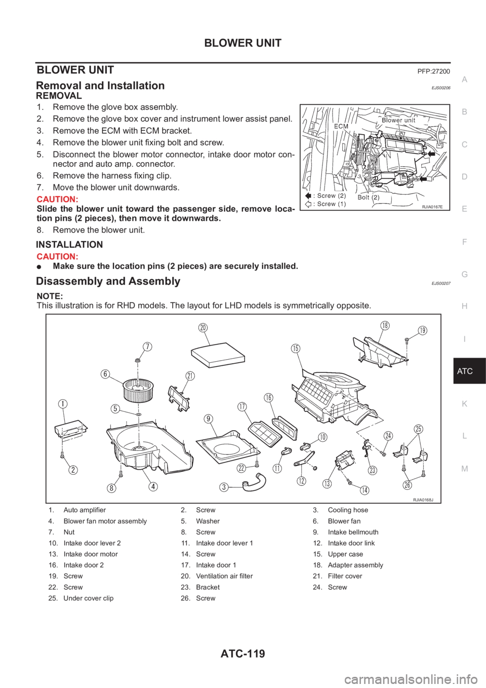
Disassembly and AssemblyEJS00207
NOTE:
This illustration is for RHD models. The layout for LHD models is symmetrically opposite.
RJIA0167E
1. Auto amplifier 2. Screw 3. Cooling hose
4. Blower fan motor assembly 5. Washer 6. Blower fan
7. Nut 8. Screw 9. Intake bellmouth
10. Intake door lever 2 11. Intake door lever 1 12. Intake door link
13. Intake door motor 14. Screw 15. Upper case
16. Intake door 2 17. Intake door 1 18. Adapter assembly
19. Screw 20. Ventilation air filter 21. Filter cover
22. Screw 23. Bracket 24. Screw
25. Under cover clip 26. Screw
RJIA0168J
Page 2124 of 3189
ATC-144
REFRIGERANT LINES
Evaporator
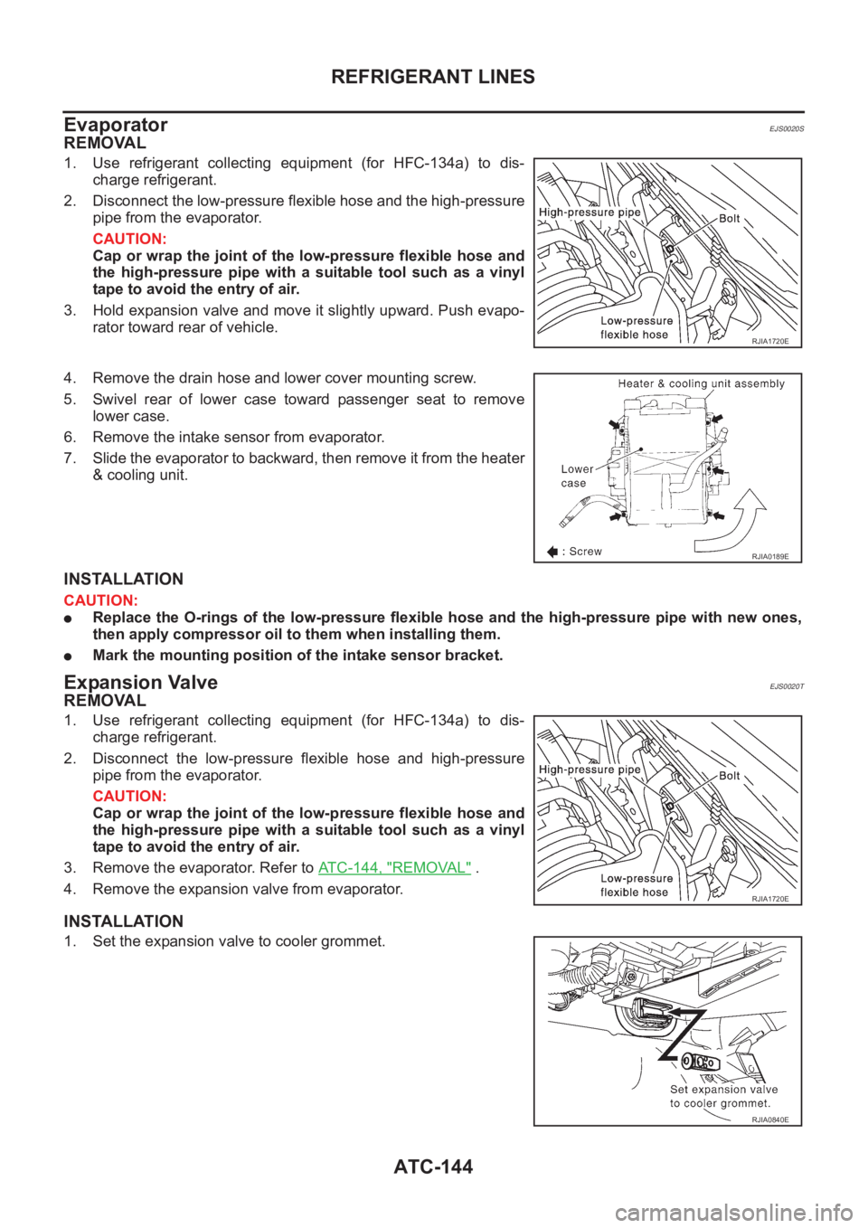
EJS0020S
REMOVAL
1. Use refrigerant collecting equipment (for HFC-134a) to dis-
charge refrigerant.
2. Disconnect the low-pressure flexible hose and the high-pressure
pipe from the evaporator.
CAUTION:
Cap or wrap the joint of the low-pressure flexible hose and
the high-pressure pipe with a suitable tool such as a vinyl
tape to avoid the entry of air.
3. Hold expansion valve and move it slightly upward. Push evapo-
rator toward rear of vehicle.
4. Remove the drain hose and lower cover mounting screw.
5. Swivel rear of lower case toward passenger seat to remove
lower case.
6. Remove the intake sensor from evaporator.
7. Slide the evaporator to backward, then remove it from the heater
& cooling unit.
INSTALLATION
CAUTION:
●Replace the O-rings of the low-pressure flexible hose and the high-pressure pipe with new ones,
then apply compressor oil to them when installing them.
●Mark the mounting position of the intake sensor bracket.
Expansion ValveEJS0020T
REMOVAL
1. Use refrigerant collecting equipment (for HFC-134a) to dis-
charge refrigerant.
2. Disconnect the low-pressure flexible hose and high-pressure
pipe from the evaporator.
CAUTION:
Cap or wrap the joint of the low-pressure flexible hose and
the high-pressure pipe with a suitable tool such as a vinyl
tape to avoid the entry of air.
3. Remove the evaporator. Refer to ATC-144, "
REMOVAL" .
4. Remove the expansion valve from evaporator.
INSTALLATION
1. Set the expansion valve to cooler grommet.
RJIA1720E
RJIA0189E
RJIA1720E
RJIA0840E