2003 NISSAN ALMERA N16 tow
[x] Cancel search: towPage 67 of 3189
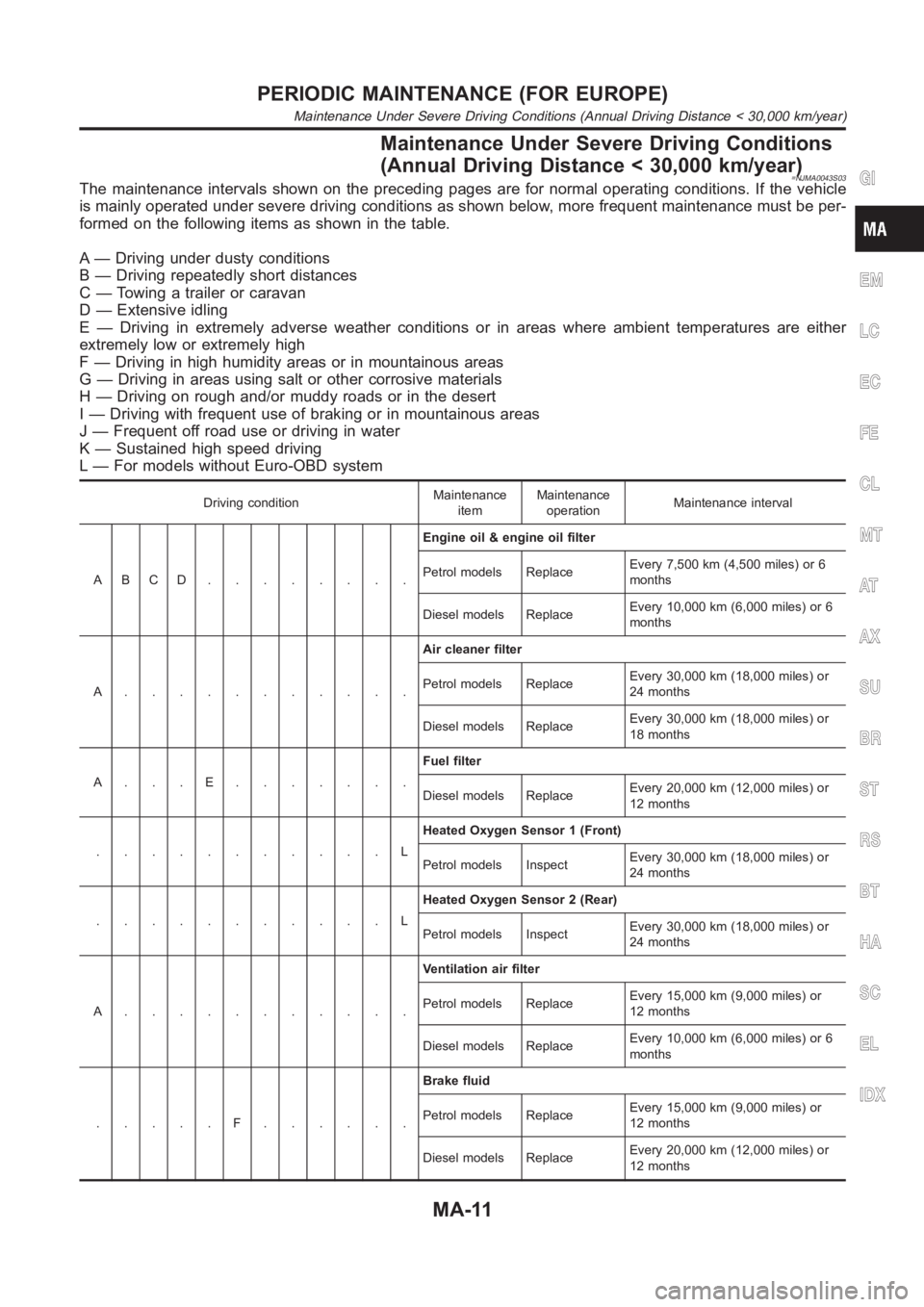
Maintenance Under Severe Driving Conditions
(Annual Driving Distance < 30,000 km/year)
=NJMA0043S03The maintenance intervals shown on the preceding pages are for normal operating conditions. If the vehicle
is mainly operated under severe driving conditions as shown below, more frequent maintenance must be per-
formed on the following items as shown in the table.
A — Driving under dusty conditions
B — Driving repeatedly short distances
C — Towing a trailer or caravan
D — Extensive idling
E — Driving in extremely adverse weather conditions or in areas where ambient temperatures are either
extremely low or extremely high
F — Driving in high humidity areas or in mountainous areas
G — Driving in areas using salt or other corrosive materials
H — Driving on rough and/or muddy roads or in the desert
I — Driving with frequent use of braking or in mountainous areas
J — Frequent off road use or driving in water
K — Sustained high speed driving
L — For models without Euro-OBD system
Driving conditionMaintenance
itemMaintenance
operationMaintenance interval
ABCD........Engine oil & engine oil filter
Petrol models ReplaceEvery 7,500 km (4,500 miles) or 6
months
Diesel models ReplaceEvery 10,000 km (6,000 miles) or 6
months
A...........Air cleaner filter
Petrol models ReplaceEvery 30,000 km (18,000 miles) or
24 months
Diesel models ReplaceEvery 30,000 km (18,000 miles) or
18 months
A...E.......Fuel filter
Diesel models ReplaceEvery 20,000 km (12,000 miles) or
12 months
...........LHeated Oxygen Sensor 1 (Front)
Petrol models InspectEvery 30,000 km (18,000 miles) or
24 months
...........LHeated Oxygen Sensor 2 (Rear)
Petrol models InspectEvery 30,000 km (18,000 miles) or
24 months
A...........Ventilation air filter
Petrol models ReplaceEvery 15,000 km (9,000 miles) or
12 months
Diesel models ReplaceEvery 10,000 km (6,000 miles) or 6
months
.....F......Brake fluid
Petrol models ReplaceEvery 15,000 km (9,000 miles) or
12 months
Diesel models ReplaceEvery 20,000 km (12,000 miles) or
12 months
GI
EM
LC
EC
FE
CL
MT
AT
AX
SU
BR
ST
RS
BT
HA
SC
EL
IDX
PERIODIC MAINTENANCE (FOR EUROPE)
Maintenance Under Severe Driving Conditions (Annual Driving Distance < 30,000 km/year)
MA-11
Page 73 of 3189
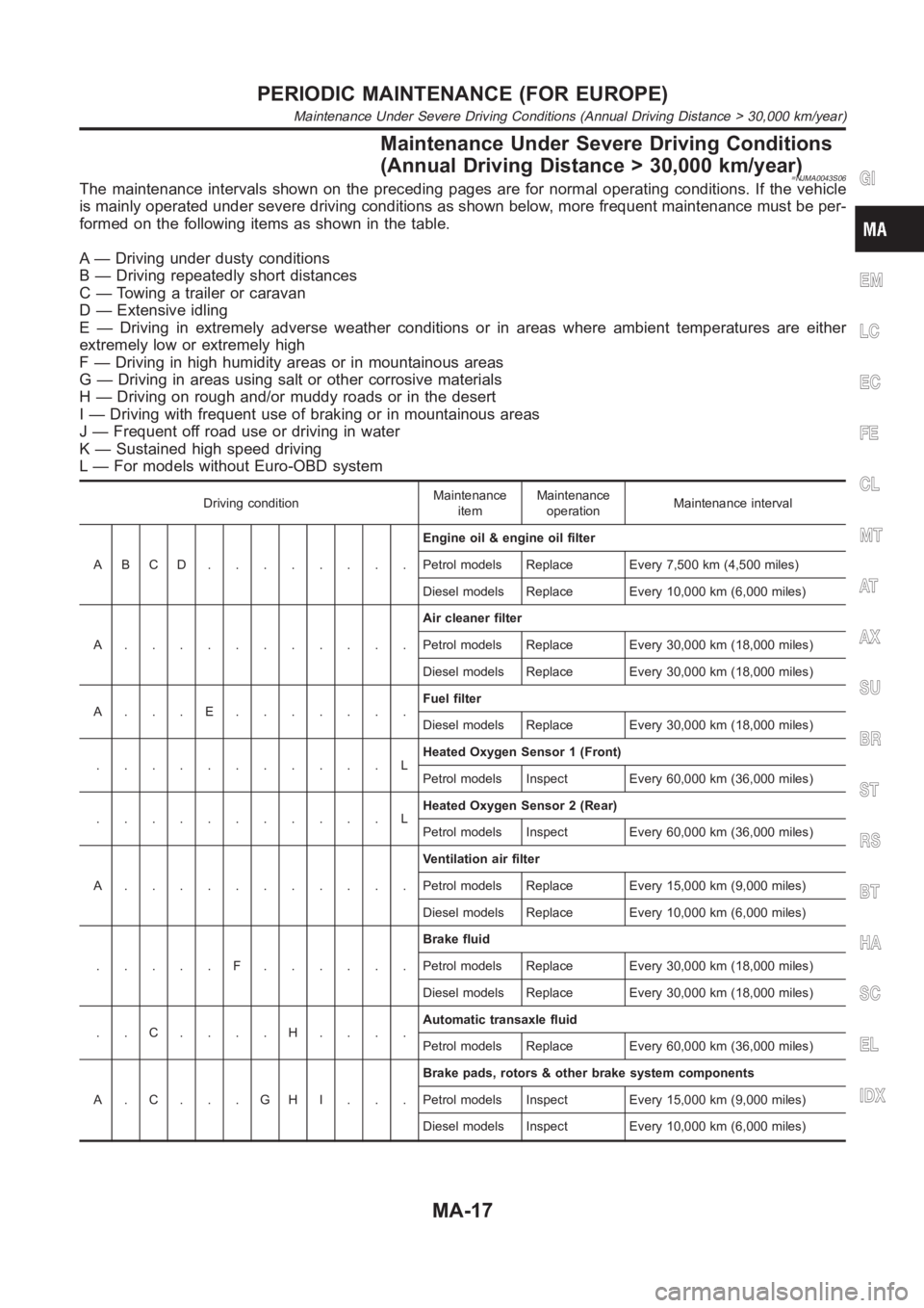
Maintenance Under Severe Driving Conditions
(Annual Driving Distance > 30,000 km/year)
=NJMA0043S06The maintenance intervals shown on the preceding pages are for normal operating conditions. If the vehicle
is mainly operated under severe driving conditions as shown below, more frequent maintenance must be per-
formed on the following items as shown in the table.
A — Driving under dusty conditions
B — Driving repeatedly short distances
C — Towing a trailer or caravan
D — Extensive idling
E — Driving in extremely adverse weather conditions or in areas where ambient temperatures are either
extremely low or extremely high
F — Driving in high humidity areas or in mountainous areas
G — Driving in areas using salt or other corrosive materials
H — Driving on rough and/or muddy roads or in the desert
I — Driving with frequent use of braking or in mountainous areas
J — Frequent off road use or driving in water
K — Sustained high speed driving
L — For models without Euro-OBD system
Driving conditionMaintenance
itemMaintenance
operationMaintenance interval
ABCD........Engine oil & engine oil filter
Petrol models Replace Every 7,500 km (4,500 miles)
Diesel models Replace Every 10,000 km (6,000 miles)
A...........Air cleaner filter
Petrol models Replace Every 30,000 km (18,000 miles)
Diesel models Replace Every 30,000 km (18,000 miles)
A...E.......Fuel filter
Diesel models Replace Every 30,000 km (18,000 miles)
...........LHeated Oxygen Sensor 1 (Front)
Petrol models Inspect Every 60,000 km (36,000 miles)
...........LHeated Oxygen Sensor 2 (Rear)
Petrol models Inspect Every 60,000 km (36,000 miles)
A...........Ventilation air filter
Petrol models Replace Every 15,000 km (9,000 miles)
Diesel models Replace Every 10,000 km (6,000 miles)
.....F......Brake fluid
Petrol models Replace Every 30,000 km (18,000 miles)
Diesel models Replace Every 30,000 km (18,000 miles)
..C....H....Automatic transaxle fluid
Petrol models Replace Every 60,000 km (36,000 miles)
A.C...GHI...Brake pads, rotors & other brake system components
Petrol models Inspect Every 15,000 km (9,000 miles)
Diesel models Inspect Every 10,000 km (6,000 miles)
GI
EM
LC
EC
FE
CL
MT
AT
AX
SU
BR
ST
RS
BT
HA
SC
EL
IDX
PERIODIC MAINTENANCE (FOR EUROPE)
Maintenance Under Severe Driving Conditions (Annual Driving Distance > 30,000 km/year)
MA-17
Page 104 of 3189
![NISSAN ALMERA N16 2003 Electronic Repair Manual EM-26
[QG]
FUEL INJECTOR AND FUEL TUBE
FUEL INJECTOR AND FUEL TUBE
PFP:16600
Removal and InstallationEBS00LQ9
CAUTION:
●Apply new engine oil when installing the parts that specified to do so in the NISSAN ALMERA N16 2003 Electronic Repair Manual EM-26
[QG]
FUEL INJECTOR AND FUEL TUBE
FUEL INJECTOR AND FUEL TUBE
PFP:16600
Removal and InstallationEBS00LQ9
CAUTION:
●Apply new engine oil when installing the parts that specified to do so in the](/manual-img/5/57350/w960_57350-103.png)
EM-26
[QG]
FUEL INJECTOR AND FUEL TUBE
FUEL INJECTOR AND FUEL TUBE
PFP:16600
Removal and InstallationEBS00LQ9
CAUTION:
●Apply new engine oil when installing the parts that specified to do so in the figure.
●Do not remove or disassembly parts unless instructed as shown in the figure.
REMOVAL
1. Release fuel pressure. Refer to EC-34, "FUEL PRESSURE RELEASE" (WITH EURO-OBD), EC-427,
"FUEL PRESSURE RELEASE" (WITHOUT EURO-OBD).
2. Disconnect harness for fuel injector, and move it aside.
3. Remove fuel hose.
CAUTION:
After removal, install blind plug to fuel hose to prevent the fuel from draining.
4. Remove fuel tube and injector assembly with the following pro-
cedure:
a. Loosen mounting bolts in reverse order shown in figure.
b. Pull out fuel injector/fuel tube assembly toward engine rear side.
YEM051
1. Fuel tube 2. Fuel feed hose 3. O-ring
4. Clip 5. Fuel injector 6. Intake manifold
PBIC0617E
Page 130 of 3189
![NISSAN ALMERA N16 2003 Electronic Repair Manual EM-52
[QG]
TIMING CHAIN
2. Install front oil seal to front cover.
●Install it so that identification letters on oil seal will face toward
front side of the engine.
●Using an oil seal drift (commer NISSAN ALMERA N16 2003 Electronic Repair Manual EM-52
[QG]
TIMING CHAIN
2. Install front oil seal to front cover.
●Install it so that identification letters on oil seal will face toward
front side of the engine.
●Using an oil seal drift (commer](/manual-img/5/57350/w960_57350-129.png)
EM-52
[QG]
TIMING CHAIN
2. Install front oil seal to front cover.
●Install it so that identification letters on oil seal will face toward
front side of the engine.
●Using an oil seal drift (commercial service tool), press oil seal
in until it is flush with end surface of mounting position.
●Make sure that oil seal outer circumference is free from dam-
age and burr.
3. Install front cover with the following procedure:
a. Install O-ring to cylinder block.
b. Using a flat-bladed screwdriver, apply a continuous bead of liq-
uid gasket to contact surface between cylinder head gasket
lower surface and cylinder block (2 locations shown in figure).
Use Genuine Liquid Gasket or equivalent.
c. Apply a continuous bead of liquid gasket to back surface of front
cover (location shown in figure).
CAUTION:
●Do not apply liquid gasket to groove A shown in figure.
●Especially for locations indicated by * mark in figure,
strictly observe application range of liquid gasket.
d. Apply liquid gasket to top surface of front cover lightly and
evenly.
Use Genuine Liquid Gasket or equivalent.
e. Install O-ring to back surface of front cover.
f. With socket of oil pump inner rotor placed on crankshaft top sur-
face (clearance between front cover top surface and cylinder
head gasket lower surface is secured), move front cover close to
cylinder block. (Right side in figure)
g. Lift front cover at an angle and install it to mounting position so
that front cover will come in contact with both cylinder head gas-
ket lower surface and cylinder block front surface at the same
time. (Right side in figure)
CAUTION:
●During work, be sure not to damage cylinder head gas-
ket.
●When installing, avoid discontinuous bead of liquid gas-
ket caused by allowing it to adhere to an unnecessary area.
PBIC0530E
PBIC0561E
PBIC0562E
PBIC0563E
Page 141 of 3189
![NISSAN ALMERA N16 2003 Electronic Repair Manual CYLINDER HEAD
EM-63
[QG]
C
D
E
F
G
H
I
J
K
L
MA
EM
VALVE GUIDE CLEARANCE
Perform this inspection before removing valve guide.
1. Make sure that the valve stem diameter is within the specification.
2. NISSAN ALMERA N16 2003 Electronic Repair Manual CYLINDER HEAD
EM-63
[QG]
C
D
E
F
G
H
I
J
K
L
MA
EM
VALVE GUIDE CLEARANCE
Perform this inspection before removing valve guide.
1. Make sure that the valve stem diameter is within the specification.
2.](/manual-img/5/57350/w960_57350-140.png)
CYLINDER HEAD
EM-63
[QG]
C
D
E
F
G
H
I
J
K
L
MA
EM
VALVE GUIDE CLEARANCE
Perform this inspection before removing valve guide.
1. Make sure that the valve stem diameter is within the specification.
2. Push the valve out by approx. 15 mm (0.59 in) toward the combustion chamber side to measure the
valve's run-out volume (in the direction of dial gauge) with dial gauge.
3. The half of the run-out volume accounts for the valve guide clearance.
VALVE GUIDE REPLACEMENT
When valve guide is removed, replace with oversized [0.2 mm (0.008 in)] valve guide.
1. To remove valve guide, heat cylinder head to 110 to 130°C (230
to 266°F) by soaking in heated oil.
2. Drive out valve guide with a press [under a 20 kN (2 ton, 2.2 US
ton, 2.0 lmp ton) pressure] or hammer and suitable tool.
3. Ream cylinder head valve guide hole.Standard
Intake : 0.020 - 0.050 mm (0.0008 - 0.0020 in)
Exhaust : 0.040 - 0.070 mm (0.0016 - 0.0028 in)
PBIC0077E
SEM008A
SEM931C
Valve guide hole diameter (for service parts):
Intake and exhaust
: 9.685 - 9.696 mm (0.3813 - 0.3817 in) dia.
SEM932C
Page 231 of 3189
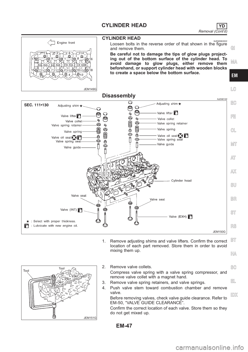
JEM149G
CYLINDER HEADNJEM0063S03Loosen bolts in the reverse order of that shown in the figure
and remove them.
Be careful not to damage the tips of glow plugs project-
ing out of the bottom surface of the cylinder head. To
avoid damage to glow plugs, either remove them
beforehand, or support cylinder head with wooden blocks
to create a space below the bottom surface.
DisassemblyNJEM0100
JEM150G
1. Remove adjusting shims and valve lifters. Confirm the correct
location of each part removed. Store them in order to avoid
mixing them up.
JEM151G
2. Remove valve collets.
Compress valve spring with a valve spring compressor, and
remove valve collet with a magnet hand.
3. Remove valve spring retainers, and valve springs.
4. Push valve stem toward combustion chamber and remove
valve.
Before removing valves, check valve guide clearance. Refer to
EM-50, “VALVE GUIDE CLEARANCE”.
Confirm the correct location of each valve. Store them so they
do not get mixed up.
GI
MA
LC
EC
FE
CL
MT
AT
AX
SU
BR
ST
RS
BT
HA
SC
EL
IDX
CYLINDER HEADYD
Removal (Cont’d)
EM-47
Page 234 of 3189
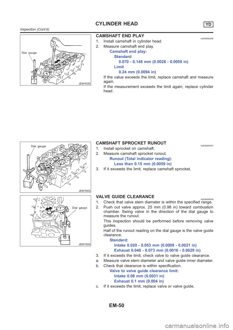
JEM163G
CAMSHAFT END PLAYNJEM0065S061. Install camshaft in cylinder head.
2. Measure camshaft end play.
Camshaft end play:
Standard
0.070 - 0.148 mm (0.0028 - 0.0058 in)
Limit
0.24 mm (0.0094 in)
If the value exceeds the limit, replace camshaft and measure
again.
If the measurement exceeds the limit again, replace cylinder
head.
JEM164G
CAMSHAFT SPROCKET RUNOUTNJEM0065S071. Install sprocket on camshaft.
2. Measure camshaft sprocket runout.
Runout (Total indicator reading):
Less than 0.15 mm (0.0059 in)
3. If it exceeds the limit, replace camshaft sprocket.
JEM155G
VALVE GUIDE CLEARANCENJEM0065S081. Check that valve stem diameter is within the specified range.
2. Push out valve approx. 25 mm (0.98 in) toward combustion
chamber. Swing valve in the direction of the dial gauge to
measure the runout.
This inspection should be performed before removing valve
guides.
Half of the runout reading on the dial gauge is the valve guide
clearance.
Standard:
Intake 0.020 - 0.053 mm (0.0008 - 0.0021 in)
Exhaust 0.040 - 0.073 mm (0.0016 - 0.0029 in)
3. If it exceeds the limit, check valve to valve guide clearance.
a. Measure valve stem diameter and valve guide inner diameter.
b. Check that clearance is within specification.
Valve to valve guide clearance limit:
Intake 0.08 mm (0.0031 in)
Exhaust 0.1 mm (0.004 in)
c. If it exceeds the limit, replace valve or valve guide.
CYLINDER HEADYD
Inspection (Cont’d)
EM-50
Page 244 of 3189
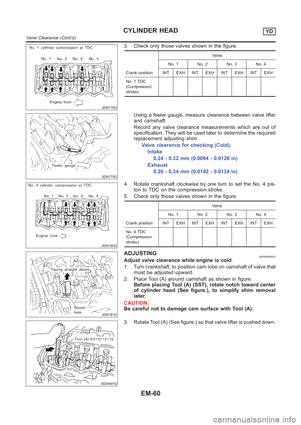
JEM178G
3. Check only those valves shown in the figure.
Crank positionValve
No. 1 No. 2 No. 3 No. 4
INT EXH INT EXH INT EXH INT EXH
No. 1 TDC
(Compression
stroke)
JEM179G
Using a feeler gauge, measure clearance between valve lifter
and camshaft.
Record any valve clearance measurements which are out of
specification. They will be used later to determine the required
replacement adjusting shim.
Valve clearance for checking (Cold):
Intake
0.24 - 0.32 mm (0.0094 - 0.0126 in)
Exhaust
0.26 - 0.34 mm (0.0102 - 0.0134 in)
JEM180G
4. Rotate crankshaft clockwise by one turn to set the No. 4 pis-
ton to TDC on the compression stroke.
5. Check only those valves shown in the figure.
Crank positionValve
No. 1 No. 2 No. 3 No. 4
INT EXH INT EXH INT EXH INT EXH
No. 4 TDC
(Compression
stroke)
JEM181G
ADJUSTINGNJEM0068S02Adjust valve clearance while engine is cold.
1. Turn crankshaft, to position cam lobe on camshaft of valve that
must be adjusted upward.
2. Place Tool (A) around camshaft as shown in figure.
Before placing Tool (A) (SST), rotate notch toward center
of cylinder head (See figure.), to simplify shim removal
later.
CAUTION:
Be careful not to damage cam surface with Tool (A).
SEM497G
3. Rotate Tool (A) (See figure.) so that valve lifter is pushed down.
CYLINDER HEADYD
Valve Clearance (Cont’d)
EM-60