Page 2191 of 3189

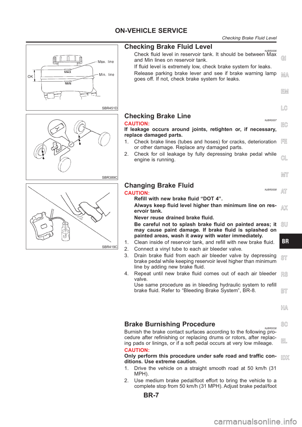
SBR451D
Checking Brake Fluid LevelNJBR0006Check fluid level in reservoir tank. It should be between Max
and Min lines on reservoir tank.
If fluid level is extremely low, check brake system for leaks.
Release parking brake lever and see if brake warning lamp
goes off. If not, check brake system for leaks.
SBR389C
Checking Brake LineNJBR0007CAUTION:
If leakage occurs around joints, retighten or, if necessary,
replace damaged parts.
1. Check brake lines (tubes and hoses) for cracks, deterioration
or other damage. Replace any damaged parts.
2. Check for oil leakage by fully depressing brake pedal while
engine is running.
SBR419C
Changing Brake FluidNJBR0008CAUTION:
Refill with new brake fluid “DOT 4”.
Always keep fluid level higher than minimum line on res-
ervoir tank.
Never reuse drained brake fluid.
Be careful not to splash brake fluid on painted areas; it
may cause paint damage. If brake fluid is splashed on
painted areas, wash it away with water immediately.
1. Clean inside of reservoir tank, and refill with new brake fluid.
2. Connect a vinyl tube to each air bleeder valve.
3. Drain brake fluid from each air bleeder valve by depressing
brake pedal while keeping reservoir level higher than minimum
line by adding new brake fluid.
4. Repeat until new brake fluid comes out of each air bleeder
valve.
Use same procedure as in bleeding hydraulic system to refill
brake fluid. Refer to “Bleeding Brake System”, BR-8.
Brake Burnishing ProcedureNJBR0036Burnish the brake contact surfaces according to the following pro-
cedure after refinishing or replacing drums or rotors, after replac-
ing pads or linings, or if a soft pedal occurs at very low mileage.
CAUTION:
Only perform this procedure under safe road and traffic con-
ditions. Use extreme caution.
1. Drive the vehicle on a straight smooth road at 50 km/h (31
MPH).
2. Use medium brake pedal/foot effort to bring the vehicle to a
complete stop from 50 km/h (31 MPH). Adjust brake pedal/foot
GI
MA
EM
LC
EC
FE
CL
MT
AT
AX
SU
ST
RS
BT
HA
SC
EL
IDX
ON-VEHICLE SERVICE
Checking Brake Fluid Level
BR-7
Page 2216 of 3189

It is not necessary to remove connecting bolt except for
disassembly or replacement of caliper assembly. In this
case, suspend cylinder body with wire so as not to stretch
brake hose.
Burnish the brake contact surfaces after refinishing or
replacing drums or rotors, after replacing pads or linings,
or if a soft pedal occurs at very low mileage.
Refer to “Brake Burnishing Procedure”, “ON-VEHICLE
SERVICE”, BR-7.
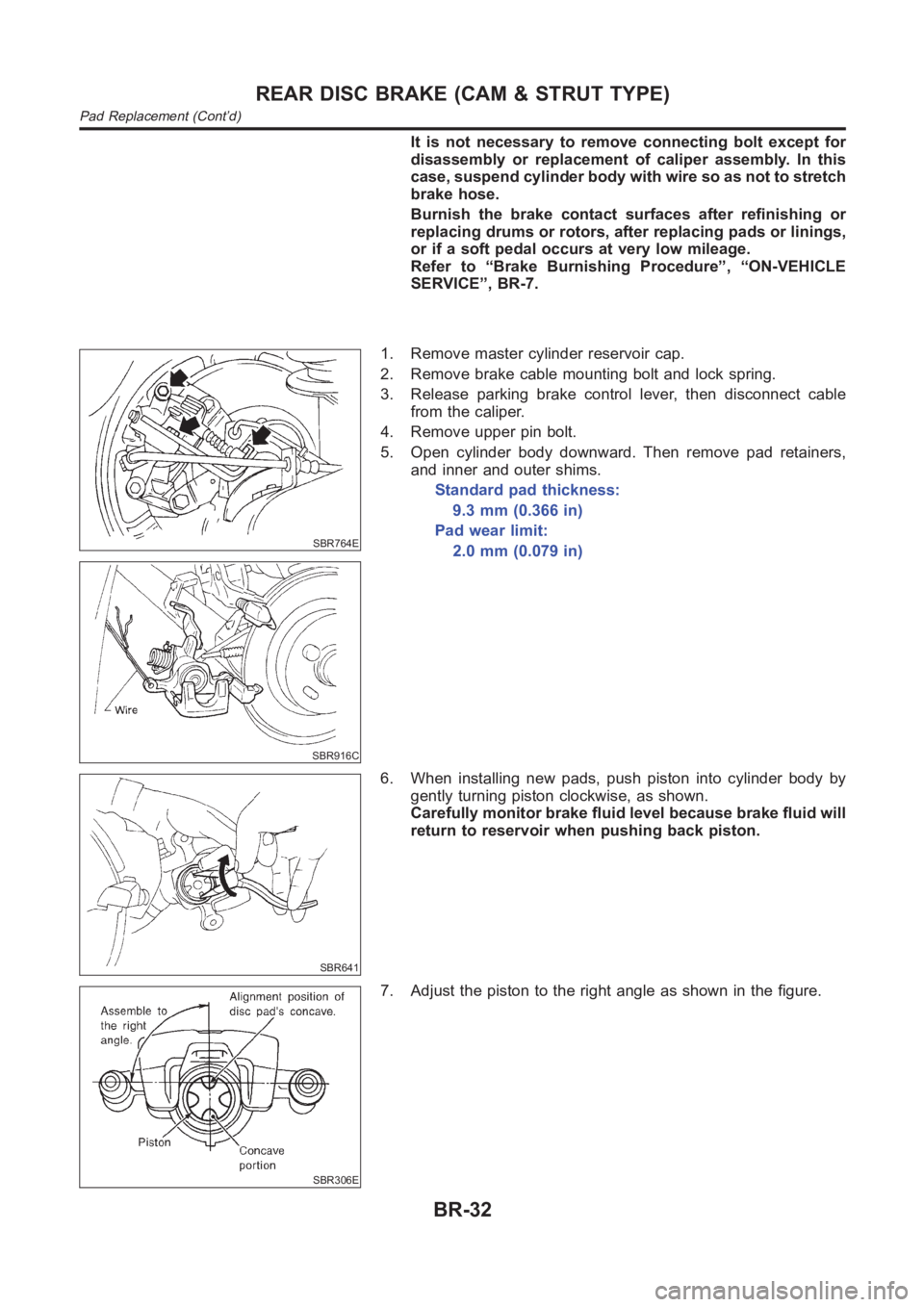
SBR764E
SBR916C
1. Remove master cylinder reservoir cap.
2. Remove brake cable mounting bolt and lock spring.
3. Release parking brake control lever, then disconnect cable
from the caliper.
4. Remove upper pin bolt.
5. Open cylinder body downward. Then remove pad retainers,
and inner and outer shims.
Standard pad thickness:
9.3mm(0.366in)
Pad wear limit:
2.0mm(0.079in)
SBR641
6. When installing new pads, push piston into cylinder body by
gently turning piston clockwise, as shown.
Carefully monitor brake fluid level because brake fluid will
return to reservoir when pushing back piston.
SBR306E
7. Adjust the piston to the right angle as shown in the figure.
REAR DISC BRAKE (CAM & STRUT TYPE)
Pad Replacement (Cont’d)
BR-32
Page 2217 of 3189

SBR307E
8. As shown in the figure, align the piston’s concave to the pad’s
convex, then install the cylinder body to the torque member.
9. Install brake cable, brake cable mounting bolt, lock spring and
master cylinder reservoir cap.
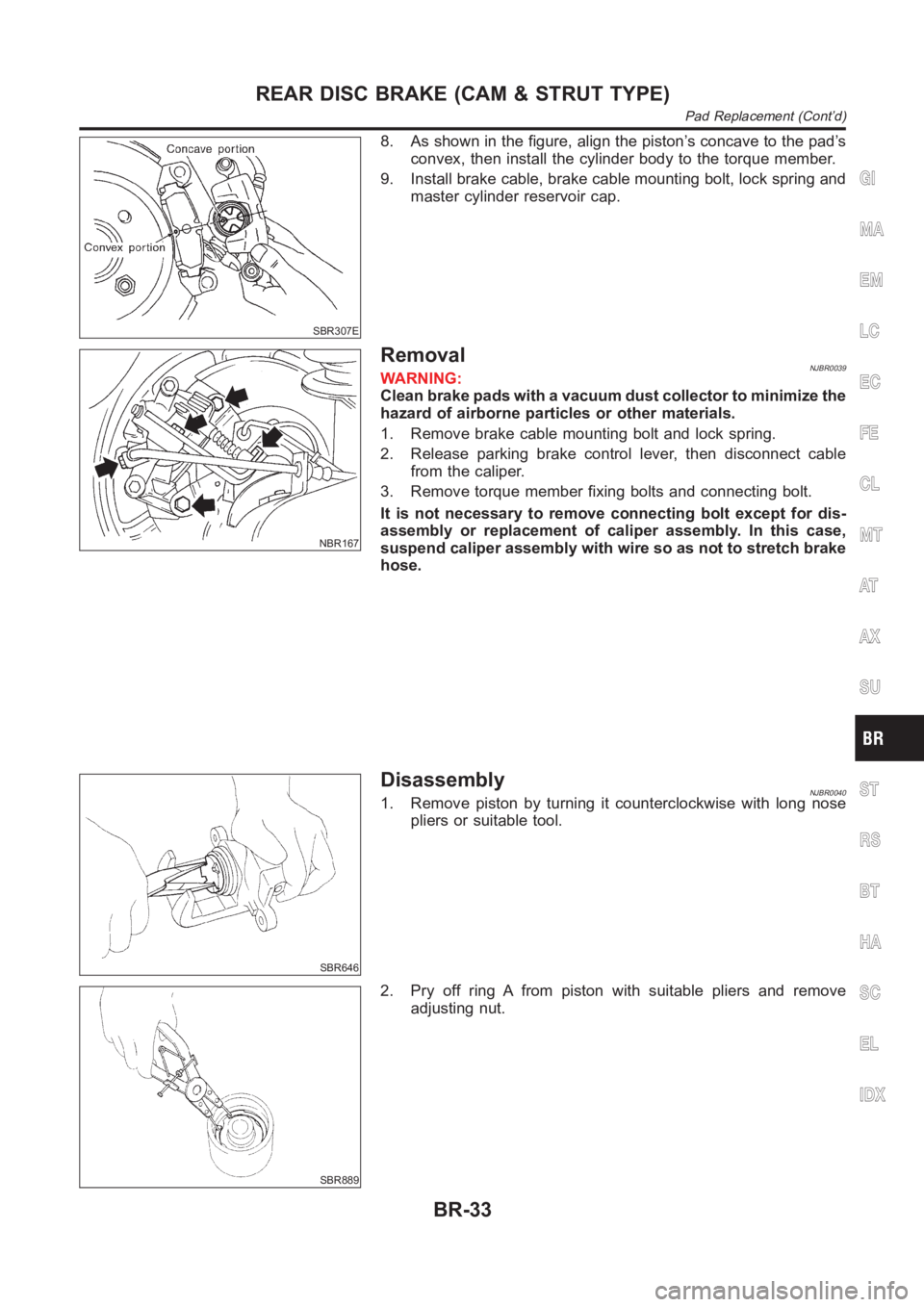
NBR167
RemovalNJBR0039WARNING:
Clean brake pads with a vacuum dust collector to minimize the
hazard of airborne particles or other materials.
1. Remove brake cable mounting bolt and lock spring.
2. Release parking brake control lever, then disconnect cable
from the caliper.
3. Remove torque member fixing bolts and connecting bolt.
It is not necessary to remove connecting bolt except for dis-
assembly or replacement of caliper assembly. In this case,
suspend caliper assembly with wire so as not to stretch brake
hose.
SBR646
DisassemblyNJBR00401. Remove piston by turning it counterclockwise with long nose
pliers or suitable tool.
SBR889
2. Pry off ring A from piston with suitable pliers and remove
adjusting nut.
GI
MA
EM
LC
EC
FE
CL
MT
AT
AX
SU
ST
RS
BT
HA
SC
EL
IDX
REAR DISC BRAKE (CAM & STRUT TYPE)
Pad Replacement (Cont’d)
BR-33
Page 2224 of 3189
NBR423
1. Remove master cylinder reservoir cap.
2. Remove brake cable lock spring.
3. Release parking brake control lever, then disconnect cable
from the caliper.
4. Remove upper pin bolt.
NBR426
5. Open cylinder body downward. Then remove pads inner and
outer shims.
Standard pad thickness:
9.3mm(0.366in)
Pad wear limit:
2.0mm(0.079in)
SBR641
6. When installing new pads, push piston into cylinder body by
gently turning piston clockwise, as shown.
Carefully monitor brake fluid level because brake fluid will
return to reservoir when pushing back piston.
NBR374
7. Adjust the piston to the right angle as shown in the figure.
NBR375
8. As shown in the figure, align the piston’s concave to the pad’s
convex, then install the cylinder body to the torque member.
9. Install brake cable, brake cable mounting bolt, lock spring and
master cylinder reservoir cap.
REAR DISC BRAKE (BALL & RAMP TYPE)
Pad Replacement (Cont’d)
BR-40
Page 2225 of 3189

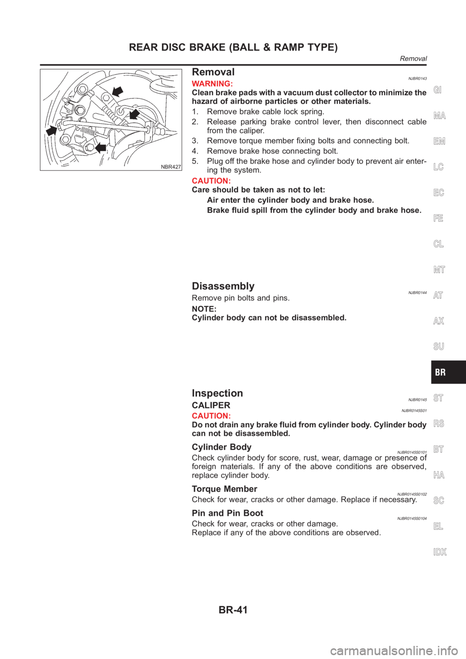
NBR427
RemovalNJBR0143WARNING:
Clean brake pads with a vacuum dust collector to minimize the
hazard of airborne particles or other materials.
1. Remove brake cable lock spring.
2. Release parking brake control lever, then disconnect cable
from the caliper.
3. Remove torque member fixing bolts and connecting bolt.
4. Remove brake hose connecting bolt.
5. Plug off the brake hose and cylinder body to prevent air enter-
ing the system.
CAUTION:
Care should be taken as not to let:
Air enter the cylinder body and brake hose.
Brake fluid spill from the cylinder body and brake hose.
DisassemblyNJBR0144Remove pin bolts and pins.
NOTE:
Cylinder body can not be disassembled.
InspectionNJBR0145CALIPERNJBR0145S01CAUTION:
Do not drain any brake fluid from cylinder body. Cylinder body
can not be disassembled.
Cylinder BodyNJBR0145S0101Check cylinder body for score, rust, wear, damage or presence of
foreign materials. If any of the above conditions are observed,
replace cylinder body.
Torque MemberNJBR0145S0102Check for wear, cracks or other damage. Replace if necessary.
Pin and Pin BootNJBR0145S0104Check for wear, cracks or other damage.
Replace if any of the above conditions are observed.
GI
MA
EM
LC
EC
FE
CL
MT
AT
AX
SU
ST
RS
BT
HA
SC
EL
IDX
REAR DISC BRAKE (BALL & RAMP TYPE)
Removal
BR-41
Page 2227 of 3189
ComponentsNJBR0044
YBR318
SBR897D
Removal and InstallationNJBR00451. To remove parking brake cable, first remove center console.
2. Disconnect warning lamp switch connector.
3. Remove adjusting nut.
4. Remove bolts and nuts securing parking brake cable.
5. Remove parking brake device.
SBR025D
6. Remove lock plate and disconnect cable.
InspectionNJBR00461. Check control lever for wear or other damage. Replace if nec-
essary.
2. Check wires for discontinuity or deterioration. Replace if nec-
essary.
3. Check warning lamp and switch. Replace if necessary.
4. Check parts at each connecting portion and, if found deformed
or damaged, replace.
GI
MA
EM
LC
EC
FE
CL
MT
AT
AX
SU
ST
RS
BT
HA
SC
EL
IDX
PARKING BRAKE CONTROL
Components
BR-43
Page 2228 of 3189
SBR768E
AdjustmentNJBR0047Before or after adjustment, pay attention to the following points.
For rear disc brake be sure that toggle lever returns to stop-
per when parking brake lever is released.
There is no drag when parking brake lever is released.
Vehicle is unladen.
1. Adjust clearance between pad and rotor as follows:
a. Release parking brake lever and loosen adjusting nut.
b. Depress brake pedal fully at least 10 times with engine run-
ning.
SBR756E
2. Pull control lever 10 times or more to make a (full) lever stroke
of 195 mm (7.68 in). At 4 to 6 notches, adjust the parking brake
cable by turning the adjusting nut.
SBR033A
3. Pull control lever with specified amount of force. Check lever
stroke and ensure smooth operation.
Number of notches
5-6
4. Bend warning lamp switch plate to ensure:
Warning lamp comes on when lever is lifted “A” notches.
Warning lamp goes out when lever is fully released.
Number of “A” notches: 1
PARKING BRAKE CONTROL
Adjustment
BR-44
Page 2258 of 3189
Parking BrakeNJBR0080
Ty p eCenter lever
Number of notches
[under force of 196 N (20 kg, 44 lb)]5-6
Number of notches
when warning lamp switch comes on1
SERVICE DATA AND SPECIFICATIONS (SDS)
Parking Brake
BR-74