2003 NISSAN ALMERA N16 SRS HARNESS
[x] Cancel search: SRS HARNESSPage 3057 of 3189
SRS797-A
Maintenance ItemsNJRS0012CAUTION:
Do not use electrical test equipment to check SRS circuit.
1. Check operation of “AIR BAG” warning lamp.
After turning ignition key to “ON” position, “AIR BAG” warning
lamp illuminates. The “AIR BAG” warning lamp will go off after
about 7 seconds if no malfunction is detected. If any of the fol-
lowing “AIR BAG” warning lamp conditions occur, immediately
check the air bag system. Refer to RS-49 for details.
The “AIR BAG” warning lamp does not illuminate when the
ignition switch is turned “ON”.
The “AIR BAG” warning lamp does not go off about 7 seconds
after the ignition switch is turned “ON”.
The “AIR BAG” warning lamp blinks after about 7 seconds after
the ignition switch is turned “ON”.
2. Visually check SRS components.
1) Diagnosis sensor unit
Check diagnosis sensor unit and bracket for dents, cracks and
deformities.
Check connectors for damage, and terminals for deformities.
2) Air bag module and steering wheel
Remove air bag module from steering wheel, instrument panel
or seatback. Check harness cover and connectors for damage,
terminals for deformities, and harness for binding.
Install driver air bag module to steering wheel to check fit or
alignment with the wheel.
Check steering wheel for excessive free play.
Install front passenger air bag module to instrument panel to
check fit or alignment with the instrument panel.
Install front side air bag module to seatback to check fit and
alignment with the seat.
3) Spiral cable
Check spiral cable for dents, cracks, or deformities.
Check connectors and protective tape for damage.
Check steering wheel for noise, binding or heavy operation.
4) Main harness, body harness, side air bag module sub-harness
Check connectors for poor connections, damage, and termi-
nals for deformities.
Check harnesses for binding, chafing or cut.
5) Front seat belt pre-tensioner
Check harness cover and connectors for damage, terminals
for deformities, and harness for binding.
Check belts for damage and anchors for loose mounting.
Check retractor for smooth operation.
Perform self-diagnosis for seat belt pre-tensioner using “AIR
BAG” warning lamp or CONSULT-II.
Refer to “SRS Operation Check” for details. (RS-49)
6) Side air bag (satellite) sensor
Check side air bag (satellite) sensor (including bracket portion)
for dents, cracks or deformities.
Check connectors for damage, and terminals for deformities.
CAUTION:
Replace previously used special bolts, hex bolts and ground
bolt with new ones.
GI
MA
EM
LC
EC
FE
CL
MT
AT
AX
SU
BR
ST
BT
HA
SC
EL
IDX
SUPPLEMENTAL RESTRAINT SYSTEM (SRS)
Maintenance Items
RS-25
Page 3062 of 3189
SHIA0239E
SRS443
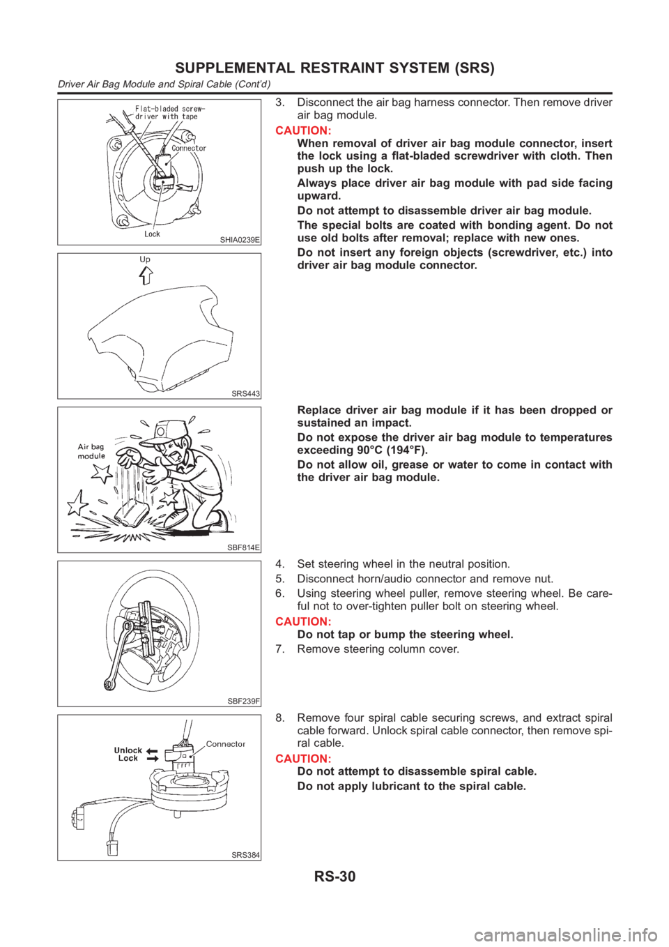
3. Disconnect the air bag harness connector. Then remove driver
air bag module.
CAUTION:
When removal of driver air bag module connector, insert
the lock using a flat-bladed screwdriver with cloth. Then
push up the lock.
Always place driver air bag module with pad side facing
upward.
Do not attempt to disassemble driver air bag module.
The special bolts are coated with bonding agent. Do not
use old bolts after removal; replace with new ones.
Do not insert any foreign objects (screwdriver, etc.) into
driver air bag module connector.
SBF814E
Replace driver air bag module if it has been dropped or
sustained an impact.
Do not expose the driver air bag module to temperatures
exceeding 90°C (194°F).
Do not allow oil, grease or water to come in contact with
the driver air bag module.
SBF239F
4. Set steering wheel in the neutral position.
5. Disconnect horn/audio connector and remove nut.
6. Using steering wheel puller, remove steering wheel. Be care-
ful not to over-tighten puller bolt on steering wheel.
CAUTION:
Do not tap or bump the steering wheel.
7. Remove steering column cover.
SRS384
8. Remove four spiral cable securing screws, and extract spiral
cable forward. Unlock spiral cable connector, then remove spi-
ral cable.
CAUTION:
Do not attempt to disassemble spiral cable.
Do not apply lubricant to the spiral cable.
SUPPLEMENTAL RESTRAINT SYSTEM (SRS)
Driver Air Bag Module and Spiral Cable (Cont’d)
RS-30
Page 3064 of 3189
SRS824
Front Passenger Air Bag Module
REMOVALNJRS0018CAUTION:
Before servicing SRS, turn the ignition switch off, discon-
nect both battery cables and wait for at least 3 minutes.
Always work from the side of or under front passenger air
bag module.
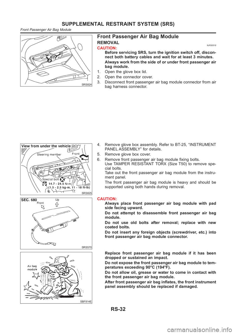
1. Open the glove box lid.
2. Open the connector cover.
3. Disconnect front passenger air bag module connector from air
bag harness connector.
SRS825
4. Remove glove box assembly. Refer to BT-25, “INSTRUMENT
PANEL ASSEMBLY” for details.
5. Remove glove box cover.
6. Remove front passenger air bag module fixing bolts.
Use TAMPER RESISTANT TORX (Size T50) to remove spe-
cial bolts.
Take out the front passenger air bag module from the instru-
ment panel.
The front passenger air bag module is heavy and should be
supported using both hands during removal.
SRS570
CAUTION:
Always place front passenger air bag module with pad
side facing upward.
Do not attempt to disassemble front passenger air bag
module.
Do not use old bolts after removal; replace with new
coated bolts.
Do not insert any foreign objects (screwdriver, etc.) into
front passenger air bag module connector.
SBF814E
Replace front passenger air bag module if it has been
dropped or sustained an impact.
Do not expose the front passenger air bag module to tem-
peratures exceeding 90°C (194°F).
Do not allow oil, grease or water to come in contact with
the front passenger air bag module.
After front passenger air bag inflates, the front instrument
panel assembly should be replaced if damaged.
SUPPLEMENTAL RESTRAINT SYSTEM (SRS)
Front Passenger Air Bag Module
RS-32
Page 3065 of 3189
SRS825
INSTALLATIONNJRS0019CAUTION:
Always work from the side of or under front passenger air
bag module.
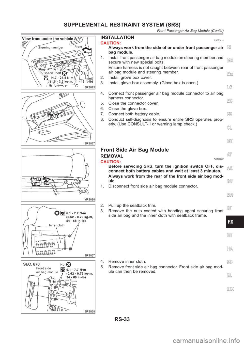
1. Install front passenger air bag module on steering member and
secure with new special bolts.
Ensure harness is not caught between rear of front passenger
air bag module and steering member.
2. Install grove box cover.
3. Install glove box assembly. (Glove box is open.)
SRS827
4. Connect front passenger air bag module connector to air bag
harness connector.
5. Close the connector cover.
6. Close the glove box.
7. Connect both battery cable.
8. Conduct self-diagnosis to ensure entire SRS operates prop-
erly. (Use CONSULT-II or warning lamp check.)
YRS098
Front Side Air Bag Module
REMOVALNJRS0059CAUTION:
Before servicing SRS, turn the ignition switch OFF, dis-
connect both battery cables and wait at least 3 minutes.
Always work from the rear of the front side air bag mod-
ule.
1. Disconnect front side air bag module connector.
SRS867
2. Pull up the seatback trim.
3. Remove the nuts coated with bonding agent securing front
side air bag and the inner cloth with seatback frame.
SRS868
4. Remove inner cloth.
5. Remove front side air bag connector. Front side air bag mod-
ule can then be removed.
GI
MA
EM
LC
EC
FE
CL
MT
AT
AX
SU
BR
ST
BT
HA
SC
EL
IDX
SUPPLEMENTAL RESTRAINT SYSTEM (SRS)
Front Passenger Air Bag Module (Cont’d)
RS-33
Page 3073 of 3189
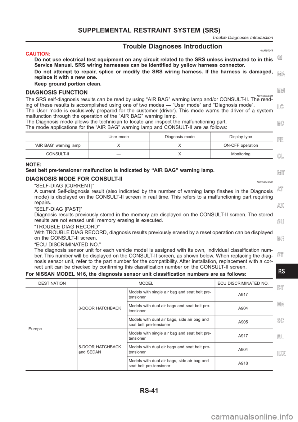
Trouble Diagnoses Introduction=NJRS0043CAUTION:
Do not use electrical test equipment on any circuit related to the SRS unless instructed to in this
Service Manual. SRS wiring harnesses can be identified by yellow harness connector.
Do not attempt to repair, splice or modify the SRS wiring harness. If the harness is damaged,
replace it with a new one.
Keep ground portion clean.
DIAGNOSIS FUNCTIONNJRS0043S01The SRS self-diagnosis results can be read by using “AIR BAG” warning lamp and/or CONSULT-II. The read-
ing of these results is accomplished using one of two modes — “User mode” and“Diagnosis mode”.
The User mode is exclusively prepared for the customer (driver). This modewarns the driver of a system
malfunction through the operation of the “AIR BAG” warning lamp.
The Diagnosis mode allows the technician to locate and inspect the malfunctioning part.
The mode applications for the “AIR BAG” warning lamp and CONSULT-II are as follows:
User mode Diagnosis mode Display type
“AIR BAG” warning lamp X X ON-OFF operation
CONSULT-II — X Monitoring
NOTE:
Seat belt pre-tensioner malfunction is indicated by “AIR BAG” warning lamp.
DIAGNOSIS MODE FOR CONSULT-IINJRS0043S02“SELF-DIAG [CURRENT]”
A current Self-diagnosis result (also indicated by the number of warning lamp flashes in the Diagnosis
mode) is displayed on the CONSULT-II screen in real time. This refers to a malfunctioning part requiring
repairs.
“SELF-DIAG [PAST]”
Diagnosis results previously stored in the memory are displayed on the CONSULT-II screen. The stored
results are not erased until memory erasing is executed.
“TROUBLE DIAG RECORD”
With TROUBLE DIAG RECORD, diagnosis results previously erased by a reset operation can be displayed
on the CONSULT-II screen.
“ECU DISCRIMINATED NO.”
The diagnosis sensor unit for each vehicle model is assigned with its own, individual classification num-
ber. This number will be displayed on the CONSULT-II screen, as shown below. When replacing the diag-
nosis sensor unit, refer to the part number for the compatibility. After installation, replacement with a cor-
rect unit can be checked by confirming this classification number on the CONSULT-II screen.
For NISSAN MODEL N16, the diagnosis sensor unit classification numbers are as follows:
DESTINATION MODEL ECU DISCRIMINATED NO.
Europe3-DOOR HATCHBACKModels with single air bag and seat belt pre-
tensionerA917
Models with dual air bags and seat belt pre-
tensionerA904
Models with dual air bags, side air bag and
seat belt pre-tensionerA905
5-DOOR HATCHBACK
and SEDANModels with single air bag and seat belt pre-
tensionerA917
Models with dual air bags and seat belt pre-
tensionerA904
Models with dual air bags, side air bag and
seat belt pre-tensionerA918
GI
MA
EM
LC
EC
FE
CL
MT
AT
AX
SU
BR
ST
BT
HA
SC
EL
IDX
SUPPLEMENTAL RESTRAINT SYSTEM (SRS)
Trouble Diagnoses Introduction
RS-41
Page 3076 of 3189
How to Perform Trouble Diagnoses for Quick
and Accurate Repair
=NJRS0044A good understanding of the malfunction conditions can make troubleshooting faster and more accurate.
In general, each customer feels differently about a malfunction. It is important to fully understand the symp-
toms or conditions for a customer complaint.
INFORMATION FROM CUSTOMERNJRS0044S01WHAT ..... Vehicle model
WHEN ..... Date, Frequencies
WHERE ..... Road conditions
HOW ..... Operating conditions, Symptoms
PRELIMINARY CHECKNJRS0044S02Check that the following parts are in good order.
Battery [Refer to SC-3, “BATTERY”.]
Fuse [Refer to EL-23, “Fuse”, “POWER SUPPLY ROUTING”.]
System component-to-harness connections
SUPPLEMENTAL RESTRAINT SYSTEM (SRS)
How to Perform Trouble Diagnoses for Quick and Accurate Repair
RS-44
Page 3081 of 3189
SRS800
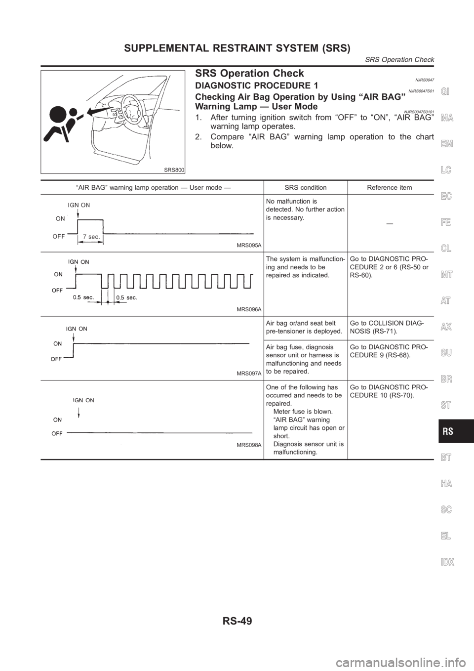
SRS Operation CheckNJRS0047DIAGNOSTIC PROCEDURE 1NJRS0047S01Checking Air Bag Operation by Using “AIR BAG”
Warning Lamp — User Mode
NJRS0047S01011. After turning ignition switch from “OFF” to “ON”, “AIR BAG”
warning lamp operates.
2. Compare “AIR BAG” warning lamp operation to the chart
below.
“AIR BAG” warning lamp operation — User mode — SRS condition Reference item
MRS095A
No malfunction is
detected. No further action
is necessary.
—
MRS096A
The system is malfunction-
ing and needs to be
repaired as indicated.Go to DIAGNOSTIC PRO-
CEDURE 2 or 6 (RS-50 or
RS-60).
MRS097A
Air bag or/and seat belt
pre-tensioner is deployed.Go to COLLISION DIAG-
NOSIS (RS-71).
Air bag fuse, diagnosis
sensor unit or harness is
malfunctioning and needs
to be repaired.Go to DIAGNOSTIC PRO-
CEDURE 9 (RS-68).
MRS098A
One of the following has
occurred and needs to be
repaired.
Meter fuse is blown.
“AIR BAG” warning
lamp circuit has open or
short.
Diagnosis sensor unit is
malfunctioning.Go to DIAGNOSTIC PRO-
CEDURE 10 (RS-70).
GI
MA
EM
LC
EC
FE
CL
MT
AT
AX
SU
BR
ST
BT
HA
SC
EL
IDX
SUPPLEMENTAL RESTRAINT SYSTEM (SRS)
SRS Operation Check
RS-49
Page 3084 of 3189
![NISSAN ALMERA N16 2003 Electronic Repair Manual Diagnostic item ExplanationRepair order
Recheck SRS at each
replacement.
AIRBAG MODULE
[OPEN]Driver air bag module circuit is open. (including the spiral
cable)1. Visually check the wiring
harness con NISSAN ALMERA N16 2003 Electronic Repair Manual Diagnostic item ExplanationRepair order
Recheck SRS at each
replacement.
AIRBAG MODULE
[OPEN]Driver air bag module circuit is open. (including the spiral
cable)1. Visually check the wiring
harness con](/manual-img/5/57350/w960_57350-3083.png)
Diagnostic item ExplanationRepair order
Recheck SRS at each
replacement.
AIRBAG MODULE
[OPEN]Driver air bag module circuit is open. (including the spiral
cable)1. Visually check the wiring
harness connection.
2. Replace the harness if it
has visible damage.
3. Replace the spiral cable.
4. Replace driver air bag mod-
ule.
(Before disposal, it must be
deployed.)
5. Replace the diagnosis sen-
sor unit.
6. Replace the related har-
ness. AIRBAG MODULE
[VB-SHORT]Driver air bag module circuit is shorted to a power supply cir-
cuit. (including the spiral cable)
AIRBAG MODULE
[GND-SHORT]Driver air bag module circuit is shorted to ground. (including
the spiral cable)
AIRBAG MODULE
[SHORT]Driver air bag module circuit is shorted between lines.
ASSIST A/B MODULE
[VB-SHORT]Front passenger air bag module circuit is shorted to a power
supply circuit.1. Visually check the wiring
harness connection.
2. Replace the harness if it
has visible damage.
3. Replace front passenger air
bag module.
(Before disposal, it must be
deployed.)
4. Replace the diagnosis sen-
sor unit.
5. Replace the related har-
ness. ASSIST A/B MODULE
[OPEN]Front passenger air bag module circuit is open.
ASSIST A/B MODULE
[GND-SHORT]Front passenger air bag module circuit is shorted to ground.
ASSIST A/B MODULE
[SHORT]Front passenger air bag module circuit is shorted between
lines.
SIDE MODULE LH
[OPEN]Front LH side air bag module circuit is open. 1. Visually check the wiring
harness connection.
2. Replace the harness if it
has visible damage.
3. Replace front LH side air
bag module.
(Before disposal, it must be
deployed.)
4. Replace the diagnosis sen-
sor unit.
5. Replace the related har-
ness. SIDE MODULE LH
[VB-SHORT]Front LH side air bag module circuit is shorted to a power
supply circuit.
SIDE MODULE LH
[GND-SHORT]Front LH side air bag module circuit is shorted to ground.
SIDE MODULE LH
[SHORT]Front LH side air bag module circuit is shorted between lines.
SIDE MODULE RH
[OPEN]Front RH side air bag module circuit is open. 1. Visually check the wiring
harness connection.
2. Replace the harness if it
has visible damage.
3. Replace front RH side air
bag module.
(Before disposal, it must be
deployed.)
4. Replace the diagnosis sen-
sor unit.
5. Replace the related har-
ness. SIDE MODULE RH
[VB-SHORT]Front RH side air bag module circuit is shorted to a power
supply circuit.
SIDE MODULE RH
[GND-SHORT]Front RH side air bag module circuit is shorted to ground.
SIDE MODULE RH
[SHORT]Front RH side air bag module circuit is shorted between
lines.
SATELLITE SENS LH
[UNIT FAIL]
SATELLITE SENS LH
[COMM FAIL]LH side air bag (satellite) sensor 1. Visually check the wiring
harness connection.
2. Replace the harness if it
has visible damage.
3. Replace the LH side air bag
(satellite) sensor.
4. Replace the diagnosis sen-
sor unit.
5. Replace the related har-
ness.
SUPPLEMENTAL RESTRAINT SYSTEM (SRS)
Trouble Diagnoses with CONSULT-II (Cont’d)
RS-52