Page 32 of 3189
SGI854
CONTROL UNIT CIRCUIT TESTNJGI0005S0306System Description: When the switch is ON, the control unit lights
up the lamp.
MGI034A
Input-output voltage chart
Pin No. Item ConditionVoltage
value VIn case of high resistance such as single strand V *
1 Switch Switch ON Battery voltage Lower than battery voltage Approx. 8 (Example)
Switch OFF Approx. 0 Approx. 0
2 Lamp Switch ON Battery voltage Approx. 0 (Inoperative lamp)
Switch OFF Approx. 0 Approx. 0
The voltage value is based on the body ground.
* : If high resistance exists in the switch side circuit (caused by a single strand), terminal 1 does not detect battery voltage. Control unit
does not detect the switch is ON even if the switch does not turn ON. Therefore, the control unit does not supply power to light up the
lamp.
HOW TO PERFORM EFFICIENT DIAGNOSES FOR AN ELECTRICAL INCIDENT
Circuit Inspection (Cont’d)
GI-30
Page 33 of 3189
MGI035A
Input-output voltage chart
Pin No. Item ConditionVoltage
value VIn case of high resistance such as single strand V *
1 Lamp Switch ON Approx. 0 Battery voltage (Inoperative lamp)
Switch OFF Battery voltage Battery voltage
2 Switch Switch ON Approx. 0 Higher than 0 Approx. 4 (Example)
Switch OFF Approx. 5 Approx. 5
The voltage value is based on the body ground.
* : If high resistance exists in the switch side circuit (caused by a single strand), terminal 2 does not detect approx. 0V. Control unit
does not detect the switch is ON even if the switch turns ON. Therefore, the control unit does not control ground to light up the lamp.
MA
EM
LC
EC
FE
CL
MT
AT
AX
SU
BR
ST
RS
BT
HA
SC
EL
IDX
HOW TO PERFORM EFFICIENT DIAGNOSES FOR AN ELECTRICAL INCIDENT
Circuit Inspection (Cont’d)
GI-31
Page 37 of 3189
Symbol Symbol explanation Symbol Symbol explanation
Check after engine is warmed up
sufficiently.Pin terminal check for SMJ type
ECM and TCM connectors.
For details regarding the terminal
arrangement, refer to the “ELEC-
TRICAL UNITS” electrical refer-
ence page at the end of the
manual.
Voltage should be measured with a
voltmeter.
Circuit resistance should be mea-
sured with an ohmmeter.
Current should be measured with an
ammeter.
Procedure with CONSULT-II
Procedure without CONSULT-II
MA
EM
LC
EC
FE
CL
MT
AT
AX
SU
BR
ST
RS
BT
HA
SC
EL
IDX
HOW TO FOLLOW TROUBLE DIAGNOSES
Key to Symbols Signifying Measurements or Procedures (Cont’d)
GI-35
Page 53 of 3189

NJGI0011
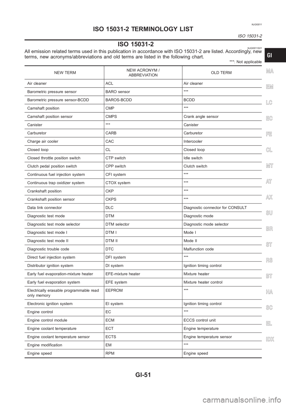
ISO 15031-2NJGI0011S01All emission related terms used in this publication in accordance with ISO15031-2 are listed. Accordingly, new
terms, new acronyms/abbreviations and old terms are listed in the following chart.
***: Not applicable
NEW TERMNEW ACRONYM /
ABBREVIATIONOLD TERM
Air cleaner ACL Air cleaner
Barometric pressure sensor BARO sensor ***
Barometric pressure sensor-BCDD BAROS-BCDD BCDD
Camshaft position CMP ***
Camshaft position sensor CMPS Crank angle sensor
Canister *** Canister
Carburetor CARB Carburetor
Charge air cooler CAC Intercooler
Closed loop CL Closed loop
Closed throttle position switch CTP switch Idle switch
Clutch pedal position switch CPP switch Clutch switch
Continuous fuel injection system CFI system ***
Continuous trap oxidizer system CTOX system ***
Crankshaft position CKP ***
Crankshaft position sensor CKPS ***
Data link connector DLC Diagnostic connector for CONSULT
Diagnostic test mode DTM Diagnostic mode
Diagnostic test mode selector DTM selector Diagnostic mode selector
Diagnostic test mode I DTM I Mode I
Diagnostic test mode II DTM II Mode II
Diagnostic trouble code DTC Malfunction code
Direct fuel injection system DFI system ***
Distributor ignition system DI system Ignition timing control
Early fuel evaporation-mixture heater EFE-mixture heater Mixture heater
Early fuel evaporation system EFE system Mixture heater control
Electrically erasable programmable read
only memoryEEPROM ***
Electronic ignition system EI system Ignition timing control
Engine control EC ***
Engine control module ECM ECCS control unit
Engine coolant temperature ECT Engine temperature
Engine coolant temperature sensor ECTS Engine temperature sensor
Engine modification EM ***
Engine speed RPM Engine speedMA
EM
LC
EC
FE
CL
MT
AT
AX
SU
BR
ST
RS
BT
HA
SC
EL
IDX
ISO 15031-2 TERMINOLOGY LIST
ISO 15031-2
GI-51
Page 54 of 3189

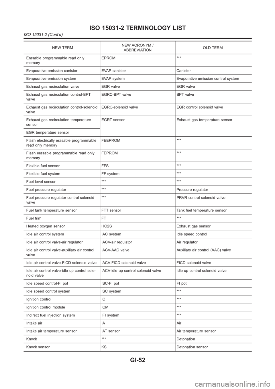
NEW TERMNEW ACRONYM /
ABBREVIATIONOLD TERM
Erasable programmable read only
memoryEPROM ***
Evaporative emission canister EVAP canister Canister
Evaporative emission system EVAP system Evaporative emission control system
Exhaust gas recirculation valve EGR valve EGR valve
Exhaust gas recirculation control-BPT
valveEGRC-BPT valve BPT valve
Exhaust gas recirculation control-solenoid
valveEGRC-solenoid valve EGR control solenoid valve
Exhaust gas recirculation temperature
sensorEGRT sensor Exhaust gas temperature sensor
EGR temperature sensor
Flash electrically erasable programmable
read only memoryFEEPROM ***
Flash erasable programmable read only
memoryFEPROM ***
Flexible fuel sensor FFS ***
Flexible fuel system FF system ***
Fuel level sensor *** ***
Fuel pressure regulator *** Pressure regulator
Fuel pressure regulator control solenoid
valve*** PRVR control solenoid valve
Fuel tank temperature sensor FTT sensor Tank fuel temperature sensor
Fuel trim FT ***
Heated oxygen sensor HO2S Exhaust gas sensor
Idle air control system IAC system Idle speed control
Idle air control valve-air regulator IACV-air regulator Air regulator
Idle air control valve-auxiliary air control
valveIACV-AAC valve Auxiliary air control (AAC) valve
Idle air control valve-FICD solenoid valve IACV-FICD solenoid valve FICDsolenoid valve
Idle air control valve-idle up control sole-
noid valveIACV-idle up control solenoid valve Idle up control solenoid valve
Idle speed control-FI pot ISC-FI pot FI pot
Idle speed control system ISC system ***
Ignition control IC ***
Ignition control module ICM ***
Indirect fuel injection system IFI system ***
Intake air IA Air
Intake air temperature sensor IAT sensor Air temperature sensor
Knock *** Detonation
Knock sensor KS Detonation sensor
ISO 15031-2 TERMINOLOGY LIST
ISO 15031-2 (Cont’d)
GI-52
Page 94 of 3189
![NISSAN ALMERA N16 2003 Electronic Repair Manual EM-16
[QG]
INTAKE MANIFOLD
INTAKE MANIFOLD
PFP:14003
Removal and InstallationEBS00LQ3
REMOVAL
WARNING:
To avoid the danger of being scalded, never drain the coolant when the engine is hot.
1. Release NISSAN ALMERA N16 2003 Electronic Repair Manual EM-16
[QG]
INTAKE MANIFOLD
INTAKE MANIFOLD
PFP:14003
Removal and InstallationEBS00LQ3
REMOVAL
WARNING:
To avoid the danger of being scalded, never drain the coolant when the engine is hot.
1. Release](/manual-img/5/57350/w960_57350-93.png)
EM-16
[QG]
INTAKE MANIFOLD
INTAKE MANIFOLD
PFP:14003
Removal and InstallationEBS00LQ3
REMOVAL
WARNING:
To avoid the danger of being scalded, never drain the coolant when the engine is hot.
1. Release fuel pressure.
Refer to EC-34, "
FUEL PRESSURE RELEASE" (WITH EURO-OBD), EC-427, "FUEL PRESSURE
RELEASE" (WITHOUT EURO-OBD).
2. Remove air duct and air cleaner case.
Refer to EM-14, "
Removal and Installation" .
3. Disconnect harness on engine top surface, and move it aside.
4. Disconnect fuel injector/fuel tube assembly from intake manifold, and move it aside.
●It is not necessary to disconnect fuel hose.
5. Disconnect the following vacuum hoses.
6. Disconnect blow-by hose (between intake manifold collector and rocker cover).
KBIA1363E
1. Electric throttle control actuator 2. Gasket 3. Intake manifold collector
4.EVAP canister purge volume control
solenoid valve5. Vacuum hose 6. Vacuum hose
7. Hose clamp 8. Intake manifold support (front) 9. Harness bracket
10. Vacuum hose 11. Intake manifold 12. PCV hose
13. Gasket 14. Vacuum hose 15. Gasket
16. Intake manifold support (rear) 17. Harness bracket 18. Intake manifold support (engine rear)
19. Grounding wire
Page 95 of 3189
INTAKE MANIFOLD
EM-17
[QG]
C
D
E
F
G
H
I
J
K
L
MA
EM
7. Loosen mounting bolts in reverse order shown in figure to
remove electric throttle control actuator.
CAUTION:
●Do not shock it.
●Do not disassembly and adjusting.
NOTE:
Remove intake manifold collector and electronic throttle control
as a single assembly, then remove electronic throttle control
itself.
8. Remove bolt on cylinder head side of intake manifold collector.
9. Loosen intake manifold collector nuts and bolts in reverse of the
order shown in the figure.
●Do not remove intake manifold collector at this stage.
10. Move harness, which is fixed on intake manifold support, with bracket.
11. Remove intake manifold supports (rear, front, engine rear).
12. Loosen nuts and bolts in reverse order shown in the figure, and
remove intake manifold from cylinder head.
13. Disconnect intake manifold collector from intake manifold, and
pull out between engine and body.
PBIC0534E
KBIA1365E
KBIA1366E
PBIC0535E
Page 96 of 3189
![NISSAN ALMERA N16 2003 Electronic Repair Manual EM-18
[QG]
INTAKE MANIFOLD
INSPECTION AFTER REMOVAL
Surface Distortion
●Using straightedge and feeler gauge, inspect surface distortion
of intake manifold collector and intake manifold surfac NISSAN ALMERA N16 2003 Electronic Repair Manual EM-18
[QG]
INTAKE MANIFOLD
INSPECTION AFTER REMOVAL
Surface Distortion
●Using straightedge and feeler gauge, inspect surface distortion
of intake manifold collector and intake manifold surfac](/manual-img/5/57350/w960_57350-95.png)
EM-18
[QG]
INTAKE MANIFOLD
INSPECTION AFTER REMOVAL
Surface Distortion
●Using straightedge and feeler gauge, inspect surface distortion
of intake manifold collector and intake manifold surface.
INSTALLATION
●Install in the reverse order of removal paying attention to the following.
Tightening Intake Manifold
●Temporarily attach before installing intake manifold collector.
●Tighten in numerical order as shown in the figure.
Tightening Intake Manifold Collector
●Temporarily attach before installing intake manifold.
●Tighten in numerical order as shown in the figure.
Installation of Electric Throttle Control Actuator
●Tighten mounting bolts for electric throttle control actuator in
numerical order shown in figure.
CAUTION:
When electric throttle control actuator is replaced, perform
idle air volume learning.
●Refer to BASIC SERVICE PROCEDURE, EC-31, "Idle Air Vol-
ume Learning" (WITH EURO-OBD), EC-425, "Idle Air Volume
Learning" (WITHOUT EURO-OBD). Limit : 0.1 mm (0.004 in)
PBIC0536E
PBIC0535E
KBIA1366E
: 17.7 - 21.6 N·m (1.8 - 2.2 kg-m, 13 - 15 ft-lb)
PBIC0534E