2003 NISSAN ALMERA N16 Electric
[x] Cancel search: ElectricPage 182 of 3189
![NISSAN ALMERA N16 2003 Electronic Repair Manual EM-104
[QG]
SERVICE DATA AND SPECIFICATIONS (SDS)
CONNECTING ROD BEARING
Standard Size
Unit: mm (in)
Undersize
Unit: mm (in)
Bearing Clearance
Unit: mm (in)
MISCELLANEOUS COMPONENTS
Unit: mm (in)
*: T NISSAN ALMERA N16 2003 Electronic Repair Manual EM-104
[QG]
SERVICE DATA AND SPECIFICATIONS (SDS)
CONNECTING ROD BEARING
Standard Size
Unit: mm (in)
Undersize
Unit: mm (in)
Bearing Clearance
Unit: mm (in)
MISCELLANEOUS COMPONENTS
Unit: mm (in)
*: T](/manual-img/5/57350/w960_57350-181.png)
EM-104
[QG]
SERVICE DATA AND SPECIFICATIONS (SDS)
CONNECTING ROD BEARING
Standard Size
Unit: mm (in)
Undersize
Unit: mm (in)
Bearing Clearance
Unit: mm (in)
MISCELLANEOUS COMPONENTS
Unit: mm (in)
*: Total indicator reading
Tightening TorqueEBS00LQQ
*1: Parts to be tightened in particular orders.
1)-: Order of tightening when tightening two or more times separately.
Unit: N·m (kg-m, ft-lb) / Unit: N·m (kg-m, in-lb)*2
Grade No. Thickness Identification color or number
0 1.503 - 1.506 (0.0592 - 0.0593) Block
1 1.506 - 1.509 (0.0593 - 0.0594) Red
2 1.509 - 1.512 (0.0594 - 0.0595) Green
Grade No. Thickness Identification color or number
0.08 (0.0031) 1.542 - 1.546 (0.0607 - 0.0609) —
0.12 (0.0047) 1.562 - 1.566 (0.0615 - 0.0617) —
0.25 (0.0098) 1.627 - 1.631 (0.0641 - 0.0642) —
Connecting rod bearing clear-
anceStandard 0.014 - 0.039 (0.0006 - 0.0015)
Limit 0.1 (0.004)
Flywheel runout [TIR*] Less than 0.1 (0.004)
Camshaft sprocket runout [TIR*] Less than 0.15 (0.0059)
Mass air flow sensor
8.4 - 10.8 (0.9 - 1.1, 75 - 95)*2
Resonator
3.8 - 4.5 (0.39 - 0.45, 34 - 39)*2
Air cleaner case lower
3.8 - 4.5 (0.39 - 0.46, 34 - 39)*2
Intake manifold16.7 - 23.5 (1.7 - 2.4, 13 - 17)
Intake manifold collector
7.0 - 9.5 (0.71 - 0.97, 62 - 84)*
2
Intake manifold support 16.7 - 23.5 (1.7 - 2.4, 13 - 17)
Electric throttle control actuator 17.7 - 21.6 (1.8 - 2.2, 13 - 15)
Exhaust manifold25.5 - 29.4 (2.6 - 2.9, 19 - 21)
Exhaust manifold cover
6.3 - 8.3 (0.64 - 0.85, 56 - 73)*
2
Heated oxygen sensor 58.8 - 78.4 (6.0 - 7.9, 44 - 57)
Ground nut79.4 (8.1, 59)
Oil pan
6.28 - 8.34 (0.64 - 0.85, 56 - 73)*
2
Oil pan drain plug29.4 - 39.2 ( 3.0 - 3.9, 22 - 28)
Oil strainer
6.28 - 8.34 (0.64 - 0.85, 56 - 73)*
2
Ignition coil
3.8 - 5.0 (0.38 - 0.51, 33 - 44)*2
Spark plug19.6 - 29.4 (2.0 - 3.0, 15 - 21)
*1 Fuel tube1) 11.8 - 13.8 (1.2 - 1.4, 9 - 10 )
2) 17 - 23 (1.7 - 2.4, 13 - 17)
Rocker cover
6.9 - 9.5 (0.70 - 0.97, 61 - 84)*
2
Page 333 of 3189
EC-3
C
D
E
F
G
H
I
J
K
L
M
ECA Component Inspection ......................................... 204
Removal and Installation ...................................... 204
DTC P0222, P0223 TP SENSOR ........................... 205
Component Description ........................................ 205
CONSULT-II Reference Value in Data Monitor Mode
. 205
On Board Diagnosis Logic ................................... 205
DTC Confirmation Procedure ............................... 205
Wiring Diagram .................................................... 207
Diagnostic Procedure ........................................... 208
Component Inspection ......................................... 210
Removal and Installation ...................................... 210
DTC P0226 APP SENSOR ......................................211
Component Description ......................................... 211
CONSULT-II Reference Value in Data Monitor Mode
.. 211
On Board Diagnosis Logic .................................... 211
DTC Confirmation Procedure ................................ 211
Wiring Diagram .................................................... 213
Diagnostic Procedure ........................................... 214
Component Inspection ......................................... 216
Removal and Installation ...................................... 217
DTC P0227, P0228 APP SENSOR ........................ 218
Component Description ........................................ 218
CONSULT-II Reference Value in Data Monitor Mode
. 218
On Board Diagnosis Logic ................................... 218
DTC Confirmation Procedure ............................... 218
Wiring Diagram .................................................... 220
Diagnostic Procedure ........................................... 221
Component Inspection ......................................... 223
Removal and Installation ...................................... 224
DTC P0300 - P0304 MULTIPLE CYLINDER MIS-
FIRE, NO. 1 - 4 CYLINDER MISFIRE ..................... 225
On Board Diagnosis Logic ................................... 225
DTC Confirmation Procedure ............................... 225
Diagnostic Procedure ........................................... 226
DTC P0327, P0328 KS ........................................... 230
Component Description ........................................ 230
On Board Diagnosis Logic ................................... 230
DTC Confirmation Procedure ............................... 230
Wiring Diagram .................................................... 231
Diagnostic Procedure ........................................... 232
Component Inspection ......................................... 233
Removal and Installation ...................................... 233
DTC P0335 CKP SENSOR (POS) .......................... 234
Component Description ........................................ 234
CONSULT-II Reference Value in Data Monitor Mode
. 234
On Board Diagnosis Logic ................................... 234
DTC Confirmation Procedure ............................... 234
Wiring Diagram ...................................................
. 235
Diagnostic Procedure ........................................... 236
Component Inspection ......................................... 238
Removal and Installation ...................................... 239
DTC P0340 CMP SENSOR (PHASE) ..................... 240
Component Description ........................................ 240
On Board Diagnosis Logic ................................... 240
DTC Confirmation Procedure ............................... 240Wiring Diagram .....................................................241
Diagnostic Procedure ...........................................242
Component Inspection ..........................................244
Removal and Installation ......................................245
DTC P0420 THREE WAY CATALYST FUNCTION . 246
On Board Diagnosis Logic ....................................246
DTC Confirmation Procedure ...............................246
Overall Function Check ........................................247
Diagnostic Procedure ...........................................248
DTC P0444 EVAP CANISTER PURGE VOLUME
CONTROL SOLENOID VALVE ...............................251
Description ............................................................251
CONSULT-II Reference Value in Data Monitor Mode
.251
On Board Diagnosis Logic ....................................252
DTC Confirmation Procedure ...............................252
Wiring Diagram .....................................................253
Diagnostic Procedure ...........................................254
Component Inspection ..........................................256
Removal and Installation ......................................256
DTC P0500 VSS ......................................................257
Description ............................................................257
On Board Diagnosis Logic ....................................257
DTC Confirmation Procedure ...............................257
Overall Function Check ........................................258
Diagnostic Procedure ...........................................259
DTC P0550 PSP SENSOR .....................................260
Component Description ........................................260
CONSULT-II Reference Value in Data Monitor Mode
.260
On Board Diagnosis Logic ....................................260
DTC Confirmation Procedure ...............................260
Wiring Diagram .....................................................261
Diagnostic Procedure ...........................................262
Component Inspection ..........................................264
DTC P0605 ECM .....................................................265
Component Description ........................................265
On Board Diagnosis Logic ....................................265
DTC Confirmation Procedure ...............................265
Diagnostic Procedure ...........................................266
DTC P1065 ECM POWER SUPPLY .......................268
Component Description ........................................268
On Board Diagnosis Logic ....................................268
DTC Confirmation Procedure ...............................268
Wiring Diagram .....................................................269
Diagnostic Procedure ...........................................270
DTC P1111 IVT CONTROL SOLENOID VALVE .....272
Component Description ........................................272
CONSULT-II Reference Value in Data Monitor Mode
.272
On Board Diagnosis Logic ....................................272
DTC Confirmation Procedure ...............................272
Wiring Diagram .....................................................273
Diagnostic Procedure ...........................................274
Component Inspection ..........................................275
Removal and Installation ......................................275
DTC P1121 ELECTRIC THROTTLE CONTROL
ACTUATOR .............................................................276
Component Description ........................................276
Page 334 of 3189
EC-4
On Board Diagnosis Logic ....................................276
DTC Confirmation Procedure ...............................276
Diagnostic Procedure ...........................................277
Removal and Installation ......................................277
DTC P1122 ELECTRIC THROTTLE CONTROL
FUNCTION ..............................................................278
Description ............................................................278
On Board Diagnosis Logic ....................................278
DTC Confirmation Procedure ...............................278
Wiring Diagram .....................................................279
Diagnostic Procedure ...........................................280
Component Inspection ..........................................284
Removal and Installation ......................................284
DTC P1124, P1126 THROTTLE CONTROL MOTOR
RELAY .....................................................................285
Component Description ........................................285
CONSULT-II Reference Value in Data Monitor Mode
.285
On Board Diagnosis Logic ....................................285
DTC Confirmation Procedure ...............................285
Wiring Diagram .....................................................287
Diagnostic Procedure ...........................................288
Component Inspection ..........................................289
DTC P1128 THROTTLE CONTROL MOTOR .........291
Component Description ........................................291
On Board Diagnosis Logic ....................................291
DTC Confirmation Procedure ...............................291
Wiring Diagram .....................................................292
Diagnostic Procedure ...........................................293
Component Inspection ..........................................294
Removal and Installation ......................................295
DTC P1143 HO2S1 .................................................296
Component Description ........................................296
CONSULT-II Reference Value in Data Monitor Mode
.296
On Board Diagnosis Logic ....................................296
DTC Confirmation Procedure ...............................297
Overall Function Check ........................................298
Diagnostic Procedure ...........................................298
Component Inspection ..........................................300
Removal and Installation ......................................301
DTC P1144 HO2S1 .................................................302
Component Description ........................................302
CONSULT-II Reference Value in Data Monitor Mode
.302
On Board Diagnosis Logic ....................................302
DTC Confirmation Procedure ...............................303
Overall Function Check ........................................304
Diagnostic Procedure ...........................................304
Component Inspection ..........................................306
Removal and Installation ......................................307
DTC P1146 HO2S2 ...............................................
..308
Component Description ........................................308
CONSULT-II Reference Value in Data Monitor Mode
.308
On Board Diagnosis Logic ....................................308
DTC Confirmation Procedure ...............................308
Overall Function Check ........................................310
Wiring Diagram .....................................................311Diagnostic Procedure ............................................312
Component Inspection ..........................................314
Removal and Installation .......................................315
DTC P1147 HO2S2 ..................................................316
Component Description ........................................316
CONSULT-II Reference Value in Data Monitor Mode
.316
On Board Diagnosis Logic ....................................316
DTC Confirmation Procedure ................................317
Overall Function Check .........................................318
Wiring Diagram .....................................................319
Diagnostic Procedure ............................................320
Component Inspection ..........................................322
Removal and Installation .......................................323
DTC P1217 ENGINE OVER TEMPERATURE ........324
System Description ...............................................324
CONSULT-II Reference Value in Data Monitor Mode
.324
On Board Diagnosis Logic ....................................325
Overall Function Check .........................................325
Wiring Diagram .....................................................327
Diagnostic Procedure ............................................328
Main 12 Causes of Overheating ...........................333
Component Inspection ..........................................334
DTC P1223, P1224 TP SENSOR ............................335
Component Description ........................................335
CONSULT-II Reference Value in Data Monitor Mode
.335
On Board Diagnosis Logic ....................................335
DTC Confirmation Procedure ................................335
Wiring Diagram .....................................................337
Diagnostic Procedure ............................................338
Component Inspection ..........................................340
Removal and Installation .......................................340
DTC P1225 TP SENSOR ........................................341
Component Description ........................................341
On Board Diagnosis Logic ....................................341
DTC Confirmation Procedure ................................341
Diagnostic Procedure ............................................342
Removal and Installation .......................................342
DTC P1226 TP SENSOR ........................................343
Component Description ........................................343
On Board Diagnosis Logic ....................................343
DTC Confirmation Procedure ................................343
Diagnostic Procedure ............................................344
Removal and Installation .......................................344
DTC P1227, P1228 APP SENSOR .........................345
Component Description ........................................345
CONSULT-II Reference Value in Data Monitor Mode
.345
On Board Diagnosis Logic ....................................345
DTC Confirmation Procedure ................................345
Wiring Diagram .....................................................347
Diagnostic Procedure ............................................348
Component Inspection ..........................................350
Removal and Installation .......................................351
DTC P1229 SENSOR POWER SUPPLY ................352
On Board Diagnosis Logic ....................................352
DTC Confirmation Procedure ................................352
Page 335 of 3189
EC-5
C
D
E
F
G
H
I
J
K
L
M
ECA Wiring Diagram .................................................... 353
Diagnostic Procedure ........................................... 354
DTC P1706 PNP SWITCH ...................................... 356
Component Description ........................................ 356
CONSULT-II Reference Value in Data Monitor Mode
. 356
On Board Diagnosis Logic ................................... 356
DTC Confirmation Procedure ............................... 356
Overall Function Check ........................................ 357
Wiring Diagram .................................................... 358
Diagnostic Procedure ........................................... 359
DTC P1805 BRAKE SWITCH ................................ 360
Description ........................................................... 360
CONSULT-II Reference Value in Data Monitor Mode
. 360
On Board Diagnosis Logic ................................... 360
DTC Confirmation Procedure ............................... 360
Wiring Diagram .................................................... 361
Diagnostic Procedure ........................................... 362
Component Inspection ......................................... 364
IGNITION SIGNAL .................................................. 365
Component Description ........................................ 365
Wiring Diagram .................................................... 366
Diagnostic Procedure ........................................... 369
Component Inspection ......................................... 373
Removal and Installation ...................................... 374
INJECTOR CIRCUIT ............................................... 375
Component Description ........................................ 375
CONSULT-II Reference Value in Data Monitor Mode
. 375
Wiring Diagram .................................................... 376
Diagnostic Procedure ........................................... 377
Component Inspection ......................................... 380
Removal and Installation ...................................... 380
FUEL PUMP CIRCUIT ............................................ 381
Description ........................................................... 381
CONSULT-II Reference Value in Data Monitor Mode
. 381
Wiring Diagram .................................................... 382
Diagnostic Procedure ........................................... 383
Component Inspection ......................................... 385
Removal and Installation ...................................... 386
REFRIGERANT PRESSURE SENSOR ................. 387
Component Description ........................................ 387
Wiring Diagram .................................................... 388
Diagnostic Procedure ........................................... 389
Removal and Installation ...................................... 391
ELECTRICAL LOAD SIGNAL ................................ 392
Description ...................................................
........ 392
CONSULT-II Reference Value in Data Monitor Mode
. 392
Wiring Diagram .................................................... 393
Diagnostic Procedure ........................................... 394
MI & DATA LINK CONNECTORS .......................... 397
Wiring Diagram—LHD Models ............................. 397
Wiring Diagram—RHD Models ............................ 398
EVAPORATIVE EMISSION SYSTEM ..................... 399
Description ........................................................... 399
Component Inspection ......................................... 401POSITIVE CRANKCASE VENTILATION ...............402
Description ............................................................402
Component Inspection ..........................................402
SERVICE DATA AND SPECIFICATIONS (SDS) ....404
Fuel Pressure .......................................................404
Idle Speed and Ignition Timing .............................404
Calculated Load Value ..........................................404
Mass Air Flow Sensor ...........................................404
Intake Air Temperature Sensor .............................404
Engine Coolant Temperature Sensor ...................404
Heated Oxygen Sensor 1 Heater .........................404
Heated Oxygen sensor 2 Heater ..........................404
Crankshaft Position Sensor (POS) .......................404
Camshaft Position Sensor (PHASE) ....................404
Throttle Control Motor ...........................................405
Injector ..................................................................405
Fuel Pump ............................................................405
QG (WITHOUT EURO-OBD)
INDEX FOR DTC .....................................................406
Alphabetical Index ................................................406
DTC No. Index ......................................................407
PRECAUTIONS ......................................................409
Precautions for Supplemental Restraint System
(SRS) “AIR BAG” and “SEAT BELT PRE-TEN-
SIONER” ...............................................................409
On Board Diagnostic (OBD) System of Engine ....409
Precaution ............................................................409
Wiring Diagrams and Trouble Diagnosis ..............412
PREPARATION .......................................................413
Special Service Tools ...........................................413
Commercial Service Tools ....................................413
ENGINE CONTROL SYSTEM ................................415
System Diagram ...................................................415
Vacuum Hose Drawing .........................................416
System Chart ........................................................417
Multiport Fuel Injection (MFI) System ...................417
Electronic Ignition (EI) System .............................419
Air Conditioning Cut Control .................................420
Fuel Cut Control (at No Load and High Engine
Speed) ..................................................................421
CAN Communication ............................................421
BASIC SERVICE PROCEDURE .............................424
Idle Speed and Ignition Timing Check ..................424
Accelerator Pedal Released Position Learning ....425
Throttle Valve Closed Position Learning ...............425
Idle Air Volume Learning ......................................425
Fuel Pressure Check ............................................427
ON BOARD DIAGNOSTIC (OBD) SYSTEM ..........429
Introduction ...........................................................429
Two Trip Detection Logic ......................................429
Emission-related Diagnostic Information ..............429
NATS (Nissan Anti-theft System) .........................431
Malfunction Indicator (MI) .....................................432
TROUBLE DIAGNOSIS ..........................................436
Trouble Diagnosis Introduction .............................436
DTC Inspection Priority Chart ...............................440
Fail-safe Chart ......................................................441
Page 337 of 3189
EC-7
C
D
E
F
G
H
I
J
K
L
M
ECA Component Inspection ......................................... 548
Removal and Installation ...................................... 549
DTC P0327, P0328 KS ........................................... 550
Component Description ........................................ 550
On Board Diagnosis Logic ................................... 550
DTC Confirmation Procedure ............................... 550
Wiring Diagram .................................................... 551
Diagnostic Procedure ........................................... 552
Component Inspection ......................................... 553
Removal and Installation ...................................... 553
DTC P0335 CKP SENSOR (POS) .......................... 554
Component Description ........................................ 554
CONSULT-II Reference Value in Data Monitor Mode
. 554
On Board Diagnosis Logic ................................... 554
DTC Confirmation Procedure ............................... 554
Wiring Diagram .................................................... 556
Diagnostic Procedure ........................................... 557
Component Inspection ......................................... 559
Removal and Installation ...................................... 560
DTC P0340 CMP SENSOR (PHASE) ..................... 561
Component Description ........................................ 561
On Board Diagnosis Logic ................................... 561
DTC Confirmation Procedure ............................... 561
Wiring Diagram .................................................... 563
Diagnostic Procedure ........................................... 564
Component Inspection ......................................... 566
Removal and Installation ...................................... 567
DTC P0605 ECM .................................................... 568
Component Description ........................................ 568
On Board Diagnosis Logic ................................... 568
DTC Confirmation Procedure ............................... 568
Diagnostic Procedure ........................................... 570
DTC P1065 ECM POWER SUPPLY ....................... 571
Component Description ........................................ 571
On Board Diagnosis Logic ................................... 571
DTC Confirmation Procedure ............................... 571
Wiring Diagram .................................................... 572
Diagnostic Procedure ........................................... 573
DTC P1121 ELECTRIC THROTTLE CONTROL
ACTUATOR ............................................................ 575
Component Description ........................................ 575
On Board Diagnosis Logic ................................... 575
DTC Confirmation Procedure ............................... 575
Diagnostic Procedure ........................................... 576
Removal and Installation ...................................... 577
DTC P1122 ELECTRIC THROTTLE CONTROL
FUNCTION .............................................................. 578
Description ..........................................................
. 578
On Board Diagnosis Logic ................................... 578
DTC Confirmation Procedure ............................... 578
Wiring Diagram .................................................... 579
Diagnostic Procedure ........................................... 580
Component Inspection ......................................... 584
Removal and Installation ...................................... 584
DTC P1124, P1126 THROTTLE CONTROL MOTOR
RELAY .................................................................... 585
Component Description ........................................ 585
CONSULT-II Reference Value in Data Monitor Mode .585
On Board Diagnosis Logic ....................................585
DTC Confirmation Procedure ...............................585
Wiring Diagram .....................................................587
Diagnostic Procedure ...........................................588
Component Inspection ..........................................590
DTC P1128 THROTTLE CONTROL MOTOR .........591
Component Description ........................................591
On Board Diagnosis Logic ....................................591
DTC Confirmation Procedure ...............................591
Wiring Diagram .....................................................592
Diagnostic Procedure ...........................................593
Component Inspection ..........................................594
Removal and Installation ......................................595
DTC P1217 ENGINE OVER TEMPERATURE ........596
System Description ...............................................596
CONSULT-II Reference Value in Data Monitor Mode
.596
On Board Diagnosis Logic ....................................597
Overall Function Check ........................................597
Wiring Diagram .....................................................599
Diagnostic Procedure ...........................................600
Main 12 Causes of Overheating ...........................605
Component Inspection ..........................................606
DTC P1223, P1224 TP SENSOR ............................607
Component Description ........................................607
CONSULT-II Reference Value in Data Monitor Mode
.607
On Board Diagnosis Logic ....................................607
DTC Confirmation Procedure ...............................607
Wiring Diagram .....................................................609
Diagnostic Procedure ...........................................610
Component Inspection ..........................................612
Removal and Installation ......................................612
DTC P1225 TP SENSOR ........................................613
Component Description ........................................613
On Board Diagnosis Logic ....................................613
DTC Confirmation Procedure ...............................613
Diagnostic Procedure ...........................................614
Removal and Installation ......................................614
DTC P1226 TP SENSOR .......................................
.615
Component Description ........................................615
On Board Diagnosis Logic ....................................615
DTC Confirmation Procedure ...............................615
Diagnostic Procedure ...........................................616
Removal and Installation ......................................616
DTC P1227, P1228 APP SENSOR .........................617
Component Description ........................................617
CONSULT-II Reference Value in Data Monitor Mode
.617
On Board Diagnosis Logic ....................................617
DTC Confirmation Procedure ...............................617
Wiring Diagram .....................................................619
Diagnostic Procedure ...........................................620
Component Inspection ..........................................622
Removal and Installation ......................................623
DTC P1229 SENSOR POWER SUPPLY ................624
On Board Diagnosis Logic ....................................624
DTC Confirmation Procedure ...............................624
Page 338 of 3189
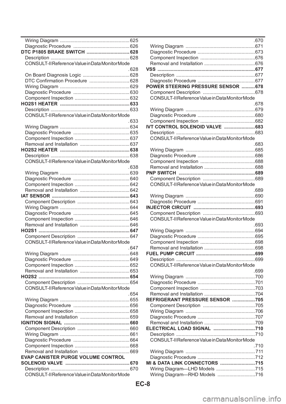
EC-8
Wiring Diagram .....................................................625
Diagnostic Procedure ...........................................626
DTC P1805 BRAKE SWITCH .................................628
Description ............................................................628
CONSULT-II Reference Value in Data Monitor Mode
.628
On Board Diagnosis Logic ....................................628
DTC Confirmation Procedure ...............................628
Wiring Diagram .....................................................629
Diagnostic Procedure ...........................................630
Component Inspection ..........................................632
HO2S1 HEATER .....................................................633
Description ............................................................633
CONSULT-II Reference Value in Data Monitor Mode
.633
Wiring Diagram .....................................................634
Diagnostic Procedure ...........................................635
Component Inspection ..........................................637
Removal and Installation ......................................637
HO2S2 HEATER .....................................................638
Description ............................................................638
CONSULT-II Reference Value in Data Monitor Mode
.638
Wiring Diagram .....................................................639
Diagnostic Procedure ...........................................640
Component Inspection ..........................................642
Removal and Installation ......................................642
IAT SENSOR ...........................................................643
Component Description ........................................643
Wiring Diagram .....................................................644
Diagnostic Procedure ...........................................645
Component Inspection ..........................................646
Removal and Installation ......................................646
HO2S1 .....................................................................647
Component Description ........................................647
CONSULT-II Reference Value in Data Monitor Mode
.647
Wiring Diagram .....................................................648
Diagnostic Procedure ...........................................649
Component Inspection ..........................................652
Removal and Installation ......................................653
HO2S2 .....................................................................654
Component Description ........................................654
CONSULT-II Reference Value in Data Monitor Mode
.654
Wiring Diagram .....................................................655
Diagnostic Procedure ...........................................656
Component Inspection ..........................................658
Removal and Installation ......................................659
IGNITION SIGNAL ..................................................660
Component Description ........................................660
Wiring Diagram .....................................................661
Diagnostic Procedure ...........................................664
Component Inspection ..........................................668
Removal and Installation ......................................669
EVAP CANISTER PURGE VOLUME CONTROL
SOLENOID VALVE .................................................670
Description ............................................................670
CONSULT-II Reference Value in Data Monitor Mode .670
Wiring Diagram .....................................................671
Diagnostic Procedure ............................................673
Component Inspection ..........................................676
Removal and Installation .......................................676
VSS ..........................................................................677
Description ............................................................677
Diagnostic Procedure ............................................677
POWER STEERING PRESSURE SENSOR ...........678
Component Description ........................................678
CONSULT-II Reference Value in Data Monitor Mode
.678
Wiring Diagram .....................................................679
Diagnostic Procedure ............................................680
Component Inspection ..........................................682
IVT CONTROL SOLENOID VALVE ........................683
Description ............................................................683
CONSULT-II Reference Value in Data Monitor Mode
.683
Wiring Diagram .....................................................685
Diagnostic Procedure ............................................686
Component Inspection ..........................................688
Removal and Installation .......................................688
PNP SWITCH ..........................................................689
Component Description ........................................689
CONSULT-II Reference Value in Data Monitor Mode
.689
Wiring Diagram .....................................................690
Diagnostic Procedure ............................................691
INJECTOR CIRCUIT ...............................................693
Component Description ........................................693
CONSULT-II Reference Value in Data Monitor Mode
.693
Wiring Diagram .....................................................694
Diagnostic Procedure ............................................695
Component Inspection ..........................................698
Removal and Installation ......................................
.698
FUEL PUMP CIRCUIT .............................................699
Description ............................................................699
CONSULT-II Reference Value in Data Monitor Mode
.699
Wiring Diagram .....................................................700
Diagnostic Procedure ............................................701
Component Inspection ..........................................703
Removal and Installation .......................................704
REFRIGERANT PRESSURE SENSOR ..................705
Component Description ........................................705
Wiring Diagram .....................................................706
Diagnostic Procedure ............................................707
Removal and Installation .......................................709
ELECTRICAL LOAD SIGNAL ................................710
Description ............................................................710
CONSULT-II Reference Value in Data Monitor Mode
.710
Wiring Diagram .....................................................711
Diagnostic Procedure ............................................712
MI & DATA LINK CONNECTORS ...........................715
Wiring Diagram—LHD Models ..............................715
Wiring Diagram—RHD Models .............................716
Page 345 of 3189
![NISSAN ALMERA N16 2003 Electronic Repair Manual PRECAUTIONS
EC-15
[QG (WITH EURO-OBD)]
C
D
E
F
G
H
I
J
K
L
MA
EC
PRECAUTIONSPFP:00001
Precautions for Supplemental Restraint System (SRS) “AIR BAG” and “SEAT
BELT PRE-TENSIONER”
EBS00K2V
The NISSAN ALMERA N16 2003 Electronic Repair Manual PRECAUTIONS
EC-15
[QG (WITH EURO-OBD)]
C
D
E
F
G
H
I
J
K
L
MA
EC
PRECAUTIONSPFP:00001
Precautions for Supplemental Restraint System (SRS) “AIR BAG” and “SEAT
BELT PRE-TENSIONER”
EBS00K2V
The](/manual-img/5/57350/w960_57350-344.png)
PRECAUTIONS
EC-15
[QG (WITH EURO-OBD)]
C
D
E
F
G
H
I
J
K
L
MA
EC
PRECAUTIONSPFP:00001
Precautions for Supplemental Restraint System (SRS) “AIR BAG” and “SEAT
BELT PRE-TENSIONER”
EBS00K2V
The Supplemental Restraint System such as “AIR BAG” and “SEAT BELT PRE-TENSIONER”, used along
with a front seat belt, helps to reduce the risk or severity of injury to the driver and front passenger for certain
types of collision. Information necessary to service the system safely is included in the SRS and SB section of
this Service Manual.
WARNING:
●To avoid rendering the SRS inoperative, which could increase the risk of personal injury or death
in the event of a collision which would result in air bag inflation, all maintenance must be per-
formed by an authorized NISSAN/INFINITI dealer.
●Improper maintenance, including incorrect removal and installation of the SRS, can lead to per-
sonal injury caused by unintentional activation of the system. For removal of Spiral Cable and Air
Bag Module, see the SRS section.
●Do not use electrical test equipment on any circuit related to the SRS unless instructed to in this
Service Manual. SRS wiring harnesses can be identified by yellow and/or orange harness connec-
tors.
On Board Diagnostic (OBD) System of Engine and A/TEBS00K2W
The ECM has an on board diagnostic system. It will light up the malfunction indicator (MI) to warn the driver of
a malfunction causing emission deterioration.
CAUTION:
●Be sure to turn the ignition switch OFF and disconnect the battery ground cable before any repair
or inspection work. The open/short circuit of related switches, sensors, solenoid valves, etc. will
cause the MI to light up.
●Be sure to connect and lock the connectors securely after work. A loose (unlocked) connector will
cause the MI to light up due to the open circuit. (Be sure the connector is free from water, grease,
dirt, bent terminals, etc.)
●Certain systems and components, especially those related to OBD, may use a new style slide-
locking type harness connector. For description and how to disconnect, refer to EL-7.
●Be sure to route and secure the harnesses properly after work. The interference of the harness
with a bracket, etc. may cause the MI to light up due to the short circuit.
●Be sure to connect rubber tubes properly after work. A misconnected or disconnected rubber tube
may cause the MI to light up due to the malfunction of the fuel injection system, etc.
●Be sure to erase the unnecessary malfunction information (repairs completed) from the ECM and
TCM (Transmission control module) before returning the vehicle to the customer.
PrecautionEBS00K2X
●Always use a 12 volt battery as power source.
●Do not attempt to disconnect battery cables while engine is
running.
●Before connecting or disconnecting the ECM harness con-
nector, turn ignition switch OFF and disconnect battery
ground cable. Failure to do so may damage the ECM
because battery voltage is applied to ECM even if ignition
switch is turned off.
●Before removing parts, turn ignition switch OFF and then
disconnect battery ground cable.
SEF289H
Page 346 of 3189
![NISSAN ALMERA N16 2003 Electronic Repair Manual EC-16
[QG (WITH EURO-OBD)]
PRECAUTIONS
●Do not disassemble ECM.
●If battery cable is disconnected, the memory will return to
the initial ECM values.
The ECM will now start to self-c NISSAN ALMERA N16 2003 Electronic Repair Manual EC-16
[QG (WITH EURO-OBD)]
PRECAUTIONS
●Do not disassemble ECM.
●If battery cable is disconnected, the memory will return to
the initial ECM values.
The ECM will now start to self-c](/manual-img/5/57350/w960_57350-345.png)
EC-16
[QG (WITH EURO-OBD)]
PRECAUTIONS
●Do not disassemble ECM.
●If battery cable is disconnected, the memory will return to
the initial ECM values.
The ECM will now start to self-control at its initial values.
Engine operation can vary slightly when the cable is dis-
connected. However, this is not an indication of a malfunc-
tion. Do not replace parts because of a slight variation.
●When connecting ECM harness connector, fasten it
securely with levers as far as they will go as shown at right.
●When connecting or disconnecting pin connectors into or
from ECM, take care not to damage pin terminals (bend or
break).
Make sure that there are not any bends or breaks on ECM
pin terminal, when connecting pin connectors.
●Securely connect ECM harness connectors.
A poor connection can cause an extremely high (surge)
voltage to develop in coil and condenser, thus resulting in
damage to ICs.
●Keep engine control system harness at least 10 cm (4 in)
away from adjacent harness, to prevent engine control sys-
tem malfunctions due to receiving external noise, degraded
operation of ICs, etc.
●Keep engine control system parts and harness dry.
●Before replacing ECM, perform “ECM Terminals and Refer-
ence Value” inspection and make sure ECM functions prop-
erly. Refer to EC-80, "
ECM Terminals and Reference Value" .
●Handle mass air flow sensor carefully to avoid damage.
●Do not disassemble mass air flow sensor.
●Do not clean mass air flow sensor with any type of deter-
gent.
●Do not disassemble electric throttle control actuator.
●Even a slight leak in the air intake system can cause seri-
ous incidents.
●Do not shock or jar the camshaft position sensor (PHASE),
crankshaft position sensor (POS).
PBIB1164E
MBIB0145E
PBIB0090E
MEF040D