2003 NISSAN ALMERA N16 Daytime
[x] Cancel search: DaytimePage 2481 of 3189
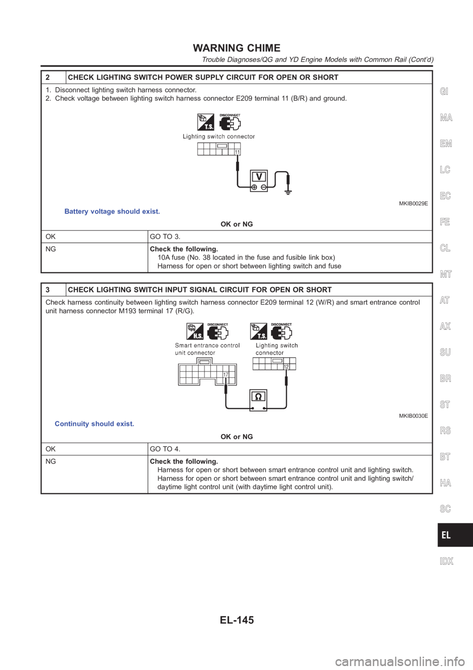
2 CHECK LIGHTING SWITCH POWER SUPPLY CIRCUIT FOR OPEN OR SHORT
1. Disconnect lighting switch harness connector.
2. Check voltage between lighting switch harness connector E209 terminal11 (B/R) and ground.
MKIB0029E
Battery voltage should exist.
OK or NG
OK GO TO 3.
NGCheck the following.
10A fuse (No. 38 located in the fuse and fusible link box)
Harness for open or short between lighting switch and fuse
3 CHECK LIGHTING SWITCH INPUT SIGNAL CIRCUIT FOR OPEN OR SHORT
Check harness continuity between lighting switch harness connector E209terminal 12 (W/R) and smart entrance control
unit harness connector M193 terminal 17 (R/G).
MKIB0030E
Continuity should exist.
OK or NG
OK GO TO 4.
NGCheck the following.
Harness for open or short between smart entrance control unit and lightingswitch.
Harness for open or short between smart entrance control unit and lightingswitch/
daytime light control unit (with daytime light control unit).
GI
MA
EM
LC
EC
FE
CL
MT
AT
AX
SU
BR
ST
RS
BT
HA
SC
IDX
WARNING CHIME
Trouble Diagnoses/QG and YD Engine Models with Common Rail (Cont’d)
EL-145
Page 2489 of 3189
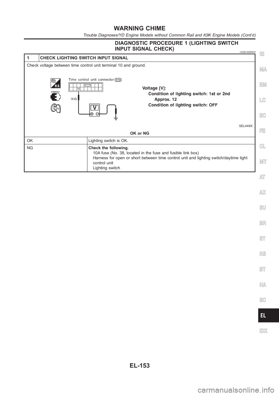
DIAGNOSTIC PROCEDURE 1 (LIGHTING SWITCH
INPUT SIGNAL CHECK)
=NJEL0455S03
1 CHECK LIGHTING SWITCH INPUT SIGNAL
Check voltage between time control unit terminal 10 and ground.
SEL449X
OK or NG
OK Lighting switch is OK.
NGCheck the following.
10A fuse (No. 38, located in the fuse and fusible link box)
Harness for open or short between time control unit and lighting switch/daytime light
control unit
Lighting switch
GI
MA
EM
LC
EC
FE
CL
MT
AT
AX
SU
BR
ST
RS
BT
HA
SC
IDX
WARNING CHIME
Trouble Diagnoses/YD Engine Models without Common Rail and K9K Engine Models (Cont’d)
EL-153
Page 2787 of 3189
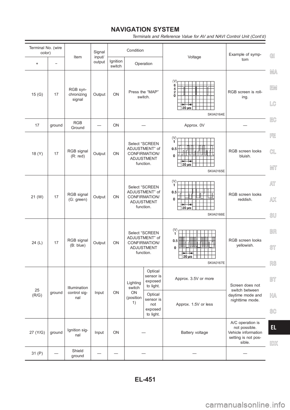
Terminal No. (wire
color)
ItemSignal
input/
outputCondition
VoltageExample of symp-
tom
+−Ignition
switchOperation
15 (G) 17RGB syn-
chronizing
signalOutput ONPress the “MAP”
switch.
SKIA0164E
RGB screen is roll-
ing.
17 groundRGB
Ground— ON — Approx. 0V —
18 (Y) 17RGB signal
(R: red)Output ONSelect “SCREEN
ADJUSTMENT” of
CONFIRMATION/
ADJUSTMENT
function.
SKIA0165E
RGB screen looks
bluish.
21 (W) 17RGB signal
(G: green)Output ONSelect “SCREEN
ADJUSTMENT” of
CONFIRMATION/
ADJUSTMENT
function.
SKIA0166E
RGB screen looks
reddish.
24 (L) 17RGB signal
(B: blue)Output ONSelect “SCREEN
ADJUSTMENT” of
CONFIRMATION/
ADJUSTMENT
function.
SKIA0167E
RGB screen looks
yellowish.
25
(R/G)groundIllumination
control sig-
nalInput ONLighting
switch
ON
(position
1)Optical
sensor is
exposed
to light.Approx. 3.5V or more
Screen does not
switch between
daytime mode and
nighttime mode. Optical
sensor is
not
exposed
to light.Approx. 1.5V or less
27 (Y/G) groundIgnition sig-
nalInput ON — Battery voltageA/C operation is
not possible.
Vehicle information
setting is not pos-
sible.
31 (P) —Shield
ground—— — — —
GI
MA
EM
LC
EC
FE
CL
MT
AT
AX
SU
BR
ST
RS
BT
HA
SC
IDX
NAVIGATION SYSTEM
Terminals and Reference Value for AV and NAVI Control Unit (Cont’d)
EL-451
Page 2836 of 3189
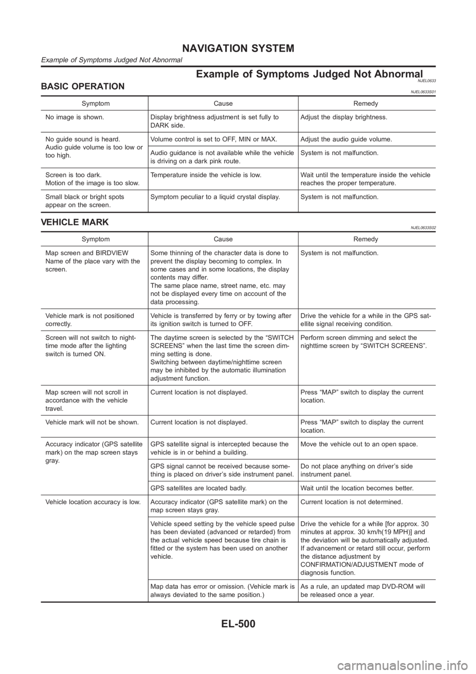
Example of Symptoms Judged Not AbnormalNJEL0633BASIC OPERATIONNJEL0633S01
Symptom Cause Remedy
No image is shown. Display brightness adjustment is set fully to
DARK side.Adjust the display brightness.
No guide sound is heard.
Audio guide volume is too low or
too high.Volume control is set to OFF, MIN or MAX. Adjust the audio guide volume.
Audio guidance is not available while the vehicle
is driving on a dark pink route.System is not malfunction.
Screen is too dark.
Motion of the image is too slow.Temperature inside the vehicle is low. Wait until the temperature inside the vehicle
reaches the proper temperature.
Small black or bright spots
appear on the screen.Symptom peculiar to a liquid crystal display. System is not malfunction.
VEHICLE MARKNJEL0633S02
Symptom Cause Remedy
Map screen and BIRDVIEW
Name of the place vary with the
screen.Some thinning of the character data is done to
prevent the display becoming to complex. In
some cases and in some locations, the display
contents may differ.
The same place name, street name, etc. may
not be displayed every time on account of the
data processing.System is not malfunction.
Vehicle mark is not positioned
correctly.Vehicle is transferred by ferry or by towing after
its ignition switch is turned to OFF.Drive the vehicle for a while in the GPS sat-
ellite signal receiving condition.
Screen will not switch to night-
time mode after the lighting
switch is turned ON.The daytime screen is selected by the “SWITCH
SCREENS” when the last time the screen dim-
ming setting is done.
Switching between daytime/nighttime screen
may be inhibited by the automatic illumination
adjustment function.Perform screen dimming and select the
nighttime screen by “SWITCH SCREENS”.
Map screen will not scroll in
accordance with the vehicle
travel.Current location is not displayed. Press “MAP” switch to display the current
location.
Vehicle mark will not be shown. Current location is not displayed. Press “MAP” switch to display the current
location.
Accuracy indicator (GPS satellite
mark) on the map screen stays
gray.GPS satellite signal is intercepted because the
vehicle is in or behind a building.Move the vehicle out to an open space.
GPS signal cannot be received because some-
thing is placed on driver’s side instrument panel.Do not place anything on driver’s side
instrument panel.
GPS satellites are located badly. Wait until the location becomes better.
Vehicle location accuracy is low. Accuracy indicator (GPS satellite mark)onthe
map screen stays gray.Current location is not determined.
Vehicle speed setting by the vehicle speed pulse
has been deviated (advanced or retarded) from
the actual vehicle speed because tire chain is
fitted or the system has been used on another
vehicle.Drive the vehicle for a while [for approx. 30
minutes at approx. 30 km/h(19 MPH)] and
the deviation will be automatically adjusted.
If advancement or retard still occur, perform
the distance adjustment by
CONFIRMATION/ADJUSTMENT mode of
diagnosis function.
Map data has error or omission. (Vehicle mark is
always deviated to the same position.)As a rule, an updated map DVD-ROM will
be released once a year.
NAVIGATION SYSTEM
Example of Symptoms Judged Not Abnormal
EL-500
Page 2935 of 3189
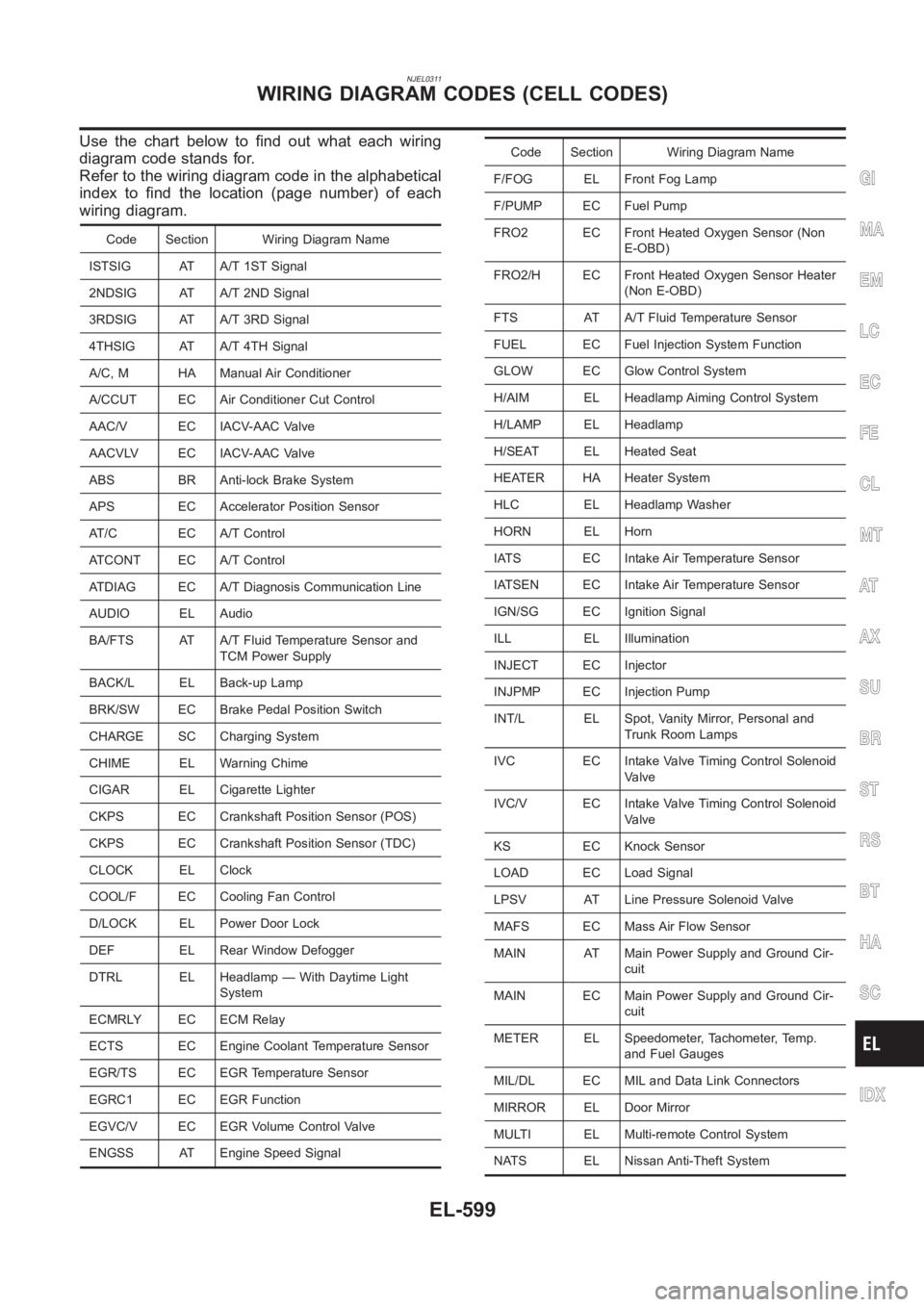
NJEL0311
Use the chart below to find out what each wiring
diagram code stands for.
Refer to the wiring diagram code in the alphabetical
index to find the location (page number) of each
wiring diagram.
Code Section Wiring Diagram Name
ISTSIG AT A/T 1ST Signal
2NDSIG AT A/T 2ND Signal
3RDSIG AT A/T 3RD Signal
4THSIG AT A/T 4TH Signal
A/C, M HA Manual Air Conditioner
A/CCUT EC Air Conditioner Cut Control
AAC/V EC IACV-AAC Valve
AACVLV EC IACV-AAC Valve
ABS BR Anti-lock Brake System
APS EC Accelerator Position Sensor
AT/C EC A/T Control
ATCONT EC A/T Control
ATDIAG EC A/T Diagnosis Communication Line
AUDIO EL Audio
BA/FTS AT A/T Fluid Temperature Sensor and
TCM Power Supply
BACK/L EL Back-up Lamp
BRK/SW EC Brake Pedal Position Switch
CHARGE SC Charging System
CHIME EL Warning Chime
CIGAR EL Cigarette Lighter
CKPS EC Crankshaft Position Sensor (POS)
CKPS EC Crankshaft Position Sensor (TDC)
CLOCK EL Clock
COOL/F EC Cooling Fan Control
D/LOCK EL Power Door Lock
DEF EL Rear Window Defogger
DTRL EL Headlamp — With Daytime Light
System
ECMRLY EC ECM Relay
ECTS EC Engine Coolant Temperature Sensor
EGR/TS EC EGR Temperature Sensor
EGRC1 EC EGR Function
EGVC/V EC EGR Volume Control Valve
ENGSS AT Engine Speed Signal
Code Section Wiring Diagram Name
F/FOG EL Front Fog Lamp
F/PUMP EC Fuel Pump
FRO2 EC Front Heated Oxygen Sensor (Non
E-OBD)
FRO2/H EC Front Heated Oxygen Sensor Heater
(Non E-OBD)
FTS AT A/T Fluid Temperature Sensor
FUEL EC Fuel Injection System Function
GLOW EC Glow Control System
H/AIM EL Headlamp Aiming Control System
H/LAMP EL Headlamp
H/SEAT EL Heated Seat
HEATER HA Heater System
HLC EL Headlamp Washer
HORN EL Horn
IATS EC Intake Air Temperature Sensor
IATSEN EC Intake Air Temperature Sensor
IGN/SG EC Ignition Signal
ILL EL Illumination
INJECT EC Injector
INJPMP EC Injection Pump
INT/L EL Spot, Vanity Mirror, Personal and
Trunk Room Lamps
IVC EC Intake Valve Timing Control Solenoid
Valve
IVC/V EC Intake Valve Timing Control Solenoid
Valve
KS EC Knock Sensor
LOAD EC Load Signal
LPSV AT Line Pressure Solenoid Valve
MAFS EC Mass Air Flow Sensor
MAIN AT Main Power Supply and Ground Cir-
cuit
MAIN EC Main Power Supply and Ground Cir-
cuit
METER EL Speedometer, Tachometer, Temp.
and Fuel Gauges
MIL/DL EC MIL and Data Link Connectors
MIRROR EL Door Mirror
MULTI EL Multi-remote Control System
NATS EL Nissan Anti-Theft System
GI
MA
EM
LC
EC
FE
CL
MT
AT
AX
SU
BR
ST
RS
BT
HA
SC
IDX
WIRING DIAGRAM CODES (CELL CODES)
EL-599
Page 3178 of 3189
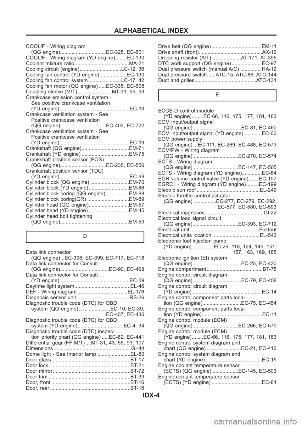
COOL/F - Wiring diagram
(QG engine)................................EC-328, EC-601
COOL/F - Wiring diagram (YD engine) ........EC-130
Coolant mixture ratio......................................MA-21
Cooling circuit (engine).............................LC-12, 36
Cooling fan control (YD engine)...................EC-130
Cooling fan control system .......................LC-17, 42
Cooling fan motor (QG engine) .....EC-335, EC-608
Coupling sleeve (M/T)........................MT-31, 55, 93
Crankcase emission control system -
See positive crankcase ventilation
(YD engine).................................................EC-19
Crankcase ventilation system - See
Positive crankcase ventilation
(QG engine)................................EC-403, EC-722
Crankcase ventilation system - See
Positive crankcase ventilation
(YD engine).................................................EC-19
Crankshaft (QG engine).................................EM-71
Crankshaft (YD engine) .................................EM-75
Crankshaft position sensor (POS)
(QG engine)................................EC-235, EC-556
Crankshaft position sensor (TDC)
(YD engine).................................................EC-99
Cylinder block (QG engine) ...........................EM-70
Cylinder block (YD engine) ............................EM-66
Cylinder block boring (QG engine) ................EM-88
Cylinder block boring(QR) .............................EM-89
Cylinder head (QG engine)............................EM-57
Cylinder head (YD engine) ............................EM-45
Cylinder head bolt tightening
(QG engine)................................................EM-59
D
Data link connector
(QG engine) ...EC-398, EC-399, EC-717, EC-718
Data link connector for Consult
(QG engine)..................................EC-90, EC-468
Data link connector for Consult
(YD engine).................................................EC-39
Daytime light system.......................................EL-46
DEF - Wiring diagram ...................................EL-176
Diagnosis sensor unit .....................................RS-26
Diagnostic trouble code (DTC) for OBD
system (QG engine) ......................EC-10, EC-39,
EC-407, EC-430
Diagnostic trouble code (DTC) for OBD
system (YD engine) ................................EC-4, 34
Diagnostic trouble code (DTC) inspec-
tion priority chart (QG engine) .....EC-62, EC-441
Differential gear (FF M/T) ....MT-31, 43, 55, 93, 107
Dimensions <0011001100110011001100110011001100110011001100110011001100110011001100110011001100110011001100110011001100110011001100110011001100110011001100110011001100110011001100110011001100110011001100110011001100
1100110011[.GI-44
Dome light - See Interior lamp .......................EL-80
Door glass <0011001100110011001100110011001100110011001100110011001100110011001100110011001100110011001100110011001100110011001100110011001100110011001100110011001100110011001100110011001100110011001100110011001100
11001100110011[.BT-17
Door lock <0011001100110011001100110011001100110011001100110011001100110011001100110011001100110011001100110011001100110011001100110011001100110011001100110011001100110011001100110011001100110011001100110011001100
110011001100110011[..BT-21
Door mirror <0011001100110011001100110011001100110011001100110011001100110011001100110011001100110011001100110011001100110011001100110011001100110011001100110011001100110011001100110011001100110011001100110011001100
1100110011[.BT-72
Door trim <0011001100110011001100110011001100110011001100110011001100110011001100110011001100110011001100110011001100110011001100110011001100110011001100110011001100110011001100110011001100110011001100110011001100
110011001100110011[..BT-39
Door, front <0011001100110011001100110011001100110011001100110011001100110011001100110011001100110011001100110011001100110011001100110011001100110011001100110011001100110011001100110011001100110011001100110011001100
1100110011[..BT-16
Door, rear <0011001100110011001100110011001100110011001100110011001100110011001100110011001100110011001100110011001100110011001100110011001100110011001100110011001100110011001100110011001100110011001100110011001100
11001100110011[..BT-16Drive belt (QG engine) ...................................EM-11
Drive shaft (front)............................................AX-10
Dropping resistor (A/T) ....................AT-171, AT-395
DTC work support (QG engine) .....................EC-97
Dual pressure switch (manual A/C) ...............HA-12
Dual pressure switch ......ATC-15, ATC-86, ATC-144
Duct and grilles...........................................ATC-131
E
ECCS-D control module
(YD engine) ........EC-66, 116, 175, 177, 181, 183
ECM input/output signal
(QG engine)..................................EC-81, EC-460
ECM input/output signal (YD engine) ............EC-66
ECM power supply
(QG engine) ...EC-111, EC-269, EC-488, EC-573
ECM/PW - Wiring diagram
(QG engine)................................EC-270, EC-574
ECTS - Wiring diagram
(QG engine)................................EC-147, EC-505
ECTS - Wiring diagram (YD engine)..............EC-84
EGR volume control valve (YD engine) .......EC-197
EGRC1 - Wiring diagram (YD engine) .........EC-199
Electric sun roof ............................................EL-249
Electric throttle control actuator
(QG engine) ................EC-277, EC-279, EC-292,
EC-577, EC-580, EC-593
Electrical diagnoses.........................................GI-22
Electrical load signal circuit
(QG engine)................................EC-393, EC-712
Electrical unit ................................................Foldout
Electrical units location .................................EL-543
Electronic fuel injection pump
(YD engine) ...............EC-25, 118, 124, 145, 151,
157, 163, 169, 185
Electronic ignition (EI) system
(QG engine)..................................EC-25, EC-420
Engine compartment .......................................BT-75
Engine control circuit diagram
(QG engine)..................................EC-79, EC-458
Engine control circuit diagram
(YD engine).................................................EC-14
Engine control component parts loca-
tion (QG engine)...........................EC-75, EC-454
Engine control component parts loca-
tion (YD engine) ..........................................EC-11
Engine control module (ECM)
(QG engine)................................EC-266, EC-570
Engine control module (ECM)
(YD engine) ........EC-66, 116, 175, 177, 181, 183
Engine control system diagram and
chart (QG engine) ........................EC-21, EC-416
Engine control system diagram and
chart (YD engine) .......................................EC-15
Engine coolant temperature sensor
(ECTS) (QG engine) ..................EC-145, EC-503
Engine coolant temperature sensor
(ECTS) (YD engine) ...................................EC-84
ALPHABETICAL INDEX
IDX-4