Page 1248 of 3189
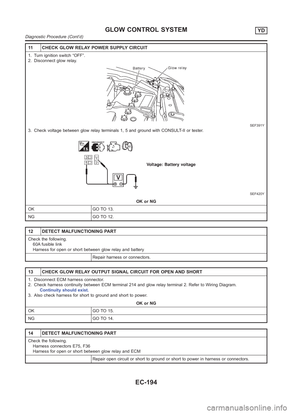
11 CHECK GLOW RELAY POWER SUPPLY CIRCUIT
1. Turn ignition switch “OFF”.
2. Disconnect glow relay.
SEF391Y
3. Check voltage between glow relay terminals 1, 5 and ground with CONSULT-II or tester.
SEF420Y
OK or NG
OK GO TO 13.
NG GO TO 12.
12 DETECT MALFUNCTIONING PART
Check the following.
60A fusible link
Harness for open or short between glow relay and battery
Repair harness or connectors.
13 CHECK GLOW RELAY OUTPUT SIGNAL CIRCUIT FOR OPEN AND SHORT
1. Disconnect ECM harness connector.
2. Check harness continuity between ECM terminal 214 and glow relay terminal 2. Refer to Wiring Diagram.
Continuity should exist.
3. Also check harness for short to ground and short to power.
OK or NG
OK GO TO 15.
NG GO TO 14.
14 DETECT MALFUNCTIONING PART
Check the following.
Harness connectors E75, F36
Harness for open or short between glow relay and ECM
Repair open circuit or short to ground or short to power in harness or connectors.
GLOW CONTROL SYSTEMYD
Diagnostic Procedure (Cont’d)
EC-194
Page 1255 of 3189
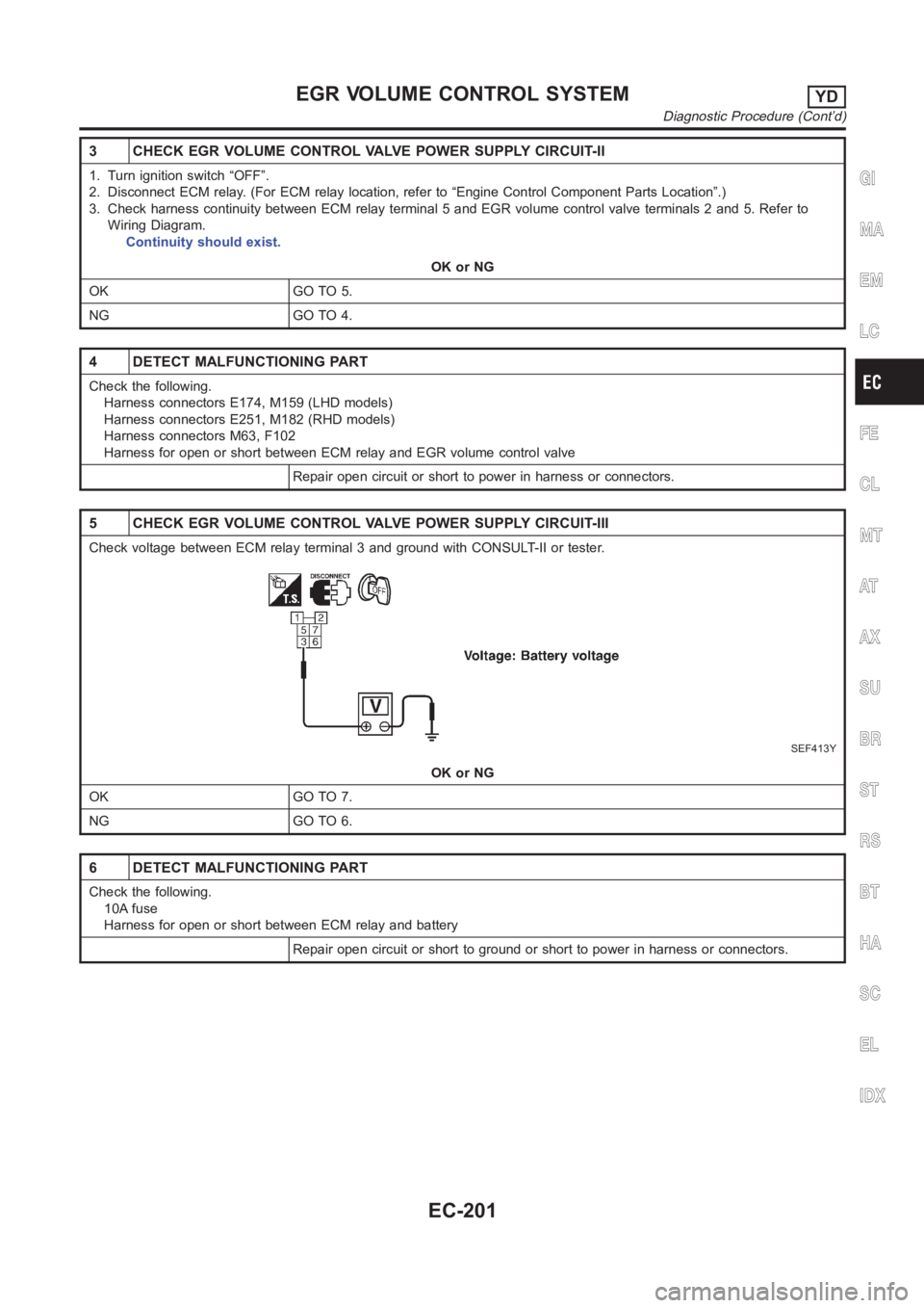
3 CHECK EGR VOLUME CONTROL VALVE POWER SUPPLY CIRCUIT-II
1. Turn ignition switch “OFF”.
2. Disconnect ECM relay. (For ECM relay location, refer to “Engine ControlComponent Parts Location”.)
3. Check harness continuity between ECM relay terminal 5 and EGR volume control valve terminals 2 and 5. Refer to
Wiring Diagram.
Continuity should exist.
OK or NG
OK GO TO 5.
NG GO TO 4.
4 DETECT MALFUNCTIONING PART
Check the following.
Harness connectors E174, M159 (LHD models)
Harness connectors E251, M182 (RHD models)
Harness connectors M63, F102
Harness for open or short between ECM relay and EGR volume control valve
Repair open circuit or short to power in harness or connectors.
5 CHECK EGR VOLUME CONTROL VALVE POWER SUPPLY CIRCUIT-III
Check voltage between ECM relay terminal 3 and ground with CONSULT-II or tester.
SEF413Y
OK or NG
OK GO TO 7.
NG GO TO 6.
6 DETECT MALFUNCTIONING PART
Check the following.
10A fuse
Harness for open or short between ECM relay and battery
Repair open circuit or short to ground or short to power in harness or connectors.
GI
MA
EM
LC
FE
CL
MT
AT
AX
SU
BR
ST
RS
BT
HA
SC
EL
IDX
EGR VOLUME CONTROL SYSTEMYD
Diagnostic Procedure (Cont’d)
EC-201
Page 1262 of 3189
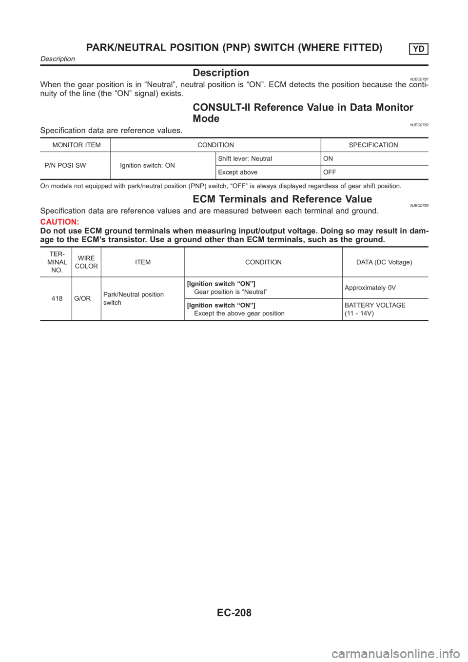
DescriptionNJEC0781When the gear position is in “Neutral”, neutral position is “ON”. ECM detects the position because the conti-
nuity of the line (the “ON” signal) exists.
CONSULT-II Reference Value in Data Monitor
Mode
NJEC0782Specification data are reference values.
MONITOR ITEM CONDITION SPECIFICATION
P/N POSI SW Ignition switch: ONShift lever: Neutral ON
Except above OFF
On models not equipped with park/neutral position (PNP) switch, “OFF” is always displayed regardless of gear shift position.
ECM Terminals and Reference ValueNJEC0783Specification data are reference values and are measured between each terminal and ground.
CAUTION:
Do not use ECM ground terminals when measuring input/output voltage. Doing so may result in dam-
age to the ECM’s transistor. Use a ground other than ECM terminals, such as the ground.
TER-
MINAL
NO.WIRE
COLORITEM CONDITION DATA (DC Voltage)
418 G/ORPark/Neutral position
switch[Ignition switch “ON”]
Gear position is “Neutral”Approximately 0V
[Ignition switch “ON”]
Except the above gear positionBATTERY VOLTAGE
(11 - 14V)
PARK/NEUTRAL POSITION (PNP) SWITCH (WHERE FITTED)YD
Description
EC-208
Page 1272 of 3189
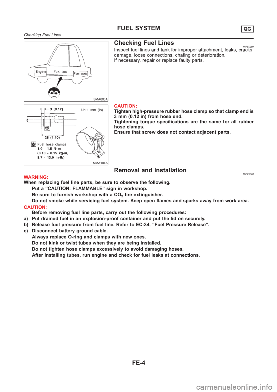
SMA803A
Checking Fuel LinesNJFE0009Inspect fuel lines and tank for improper attachment, leaks, cracks,
damage, loose connections, chafing or deterioration.
If necessary, repair or replace faulty parts.
MMA104A
CAUTION:
Tighten high-pressure rubber hose clamp so that clamp end is
3 mm (0.12 in) from hose end.
Tightening torque specifications are the same for all rubber
hose clamps.
Ensure that screw does not contact adjacent parts.
Removal and InstallationNJFE0004WARNING:
When replacing fuel line parts, be sure to observe the following.
Put a “CAUTION: FLAMMABLE” sign in workshop.
Be sure to furnish workshop with a CO
2fire extinguisher.
Do not smoke while servicing fuel system. Keep open flames and sparks away from work area.
CAUTION:
Before removing fuel line parts, carry out the following procedures:
a) Put drained fuel in an explosion-proof container and put the lid on securely.
b) Release fuel pressure from fuel line. Refer to EC-34, “Fuel Pressure Release”.
c) Disconnect battery ground cable.
Always replace O-ring and clamps with new ones.
Do not kink or twist tubes when they are being installed.
Do not tighten hose clamps excessively to avoid damaging hoses.
After installing tubes, run engine and check for fuel leaks at connections.
FUEL SYSTEMQG
Checking Fuel Lines
FE-4
Page 1273 of 3189
Fuel TankNJFE0006
YFE013
JFE613A
REMOVALNJFE0006S011. Release fuel pressure from fuel line.
Refer to EC-34, “Fuel Pressure Release”.
2. Disconnect battery ground cable.
3. Open fuel filler lid and filler cap.
4. Drain fuel from fuel tank.
5. Remove rear seat cushion. Refer to BT-59, “Removal and
Installation”.
6. Remove inspection hole cover under the rear seat.
GI
MA
EM
LC
EC
CL
MT
AT
AX
SU
BR
ST
RS
BT
HA
SC
EL
IDX
FUEL SYSTEMQG
Fuel Tank
FE-5
Page 1274 of 3189
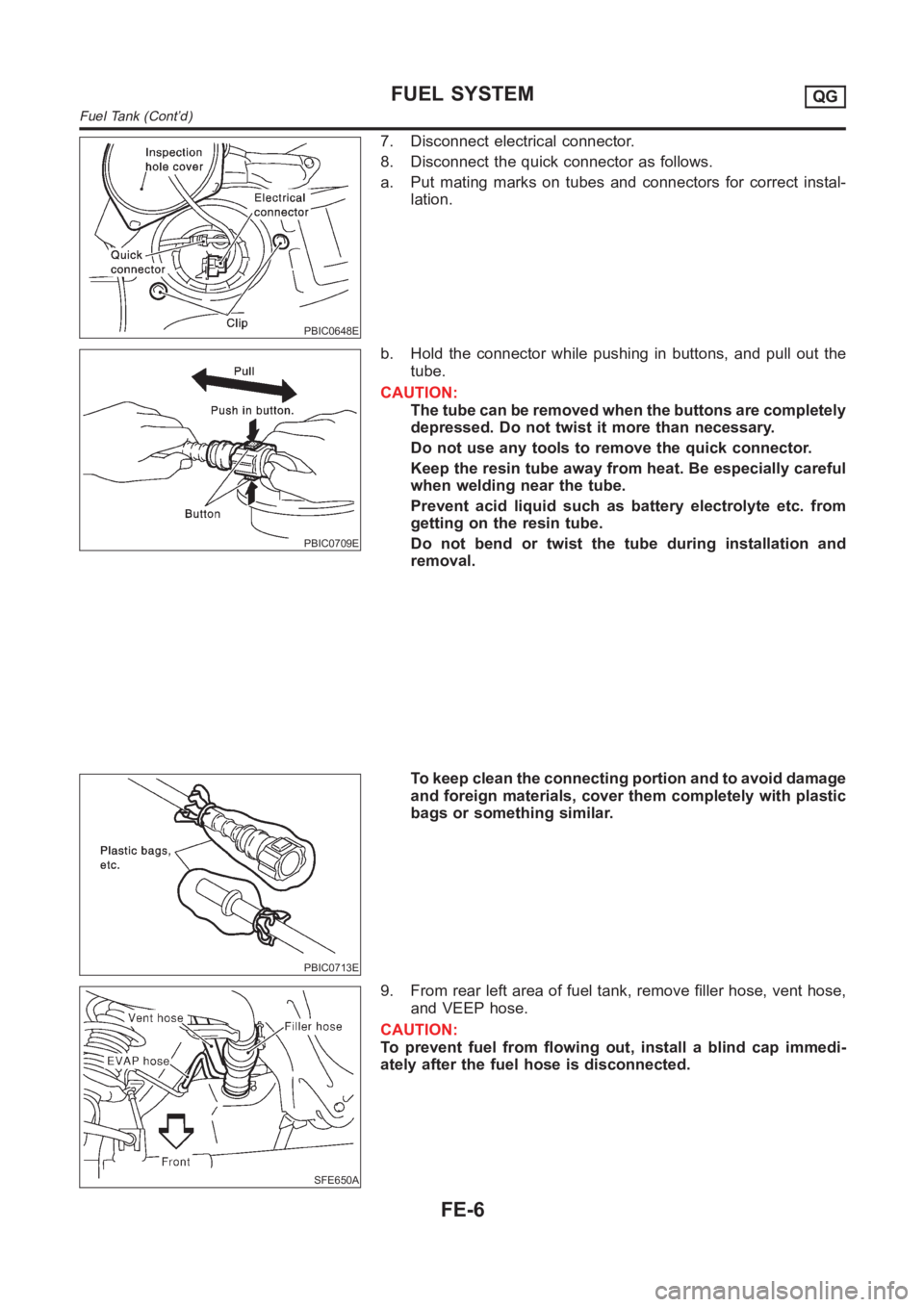
PBIC0648E
7. Disconnect electrical connector.
8. Disconnect the quick connector as follows.
a. Put mating marks on tubes and connectors for correct instal-
lation.
PBIC0709E
b. Hold the connector while pushing in buttons, and pull out the
tube.
CAUTION:
The tube can be removed when the buttons are completely
depressed. Do not twist it more than necessary.
Do not use any tools to remove the quick connector.
Keep the resin tube away from heat. Be especially careful
when welding near the tube.
Prevent acid liquid such as battery electrolyte etc. from
getting on the resin tube.
Do not bend or twist the tube during installation and
removal.
PBIC0713E
To keep clean the connecting portion and to avoid damage
and foreign materials, cover them completely with plastic
bags or something similar.
SFE650A
9. From rear left area of fuel tank, remove filler hose, vent hose,
and VEEP hose.
CAUTION:
To prevent fuel from flowing out, install a blind cap immedi-
ately after the fuel hose is disconnected.
FUEL SYSTEMQG
Fuel Tank (Cont’d)
FE-6
Page 1276 of 3189
Fuel Pump, Fuel Level Sensor Unit and Fuel
Filter
NJFE0007
YFE030
JFE613A
REMOVALNJFE0007S011. Release fuel pressure from fuel line.
Refer to EC-34, “Fuel Pressure Release”.
2. Disconnect battery ground cable.
3. Open fuel filler lid and filler cap.
4. Remove rear seat cushion. Refer to BT-59, “Removal and
Installation”.
5. Remove inspection hole cover under the rear seat.
PBIC0648E
6. Disconnect electrical connector.
7. Disconnect the quick connectors.
For disconnect of quick connectors, refer to step 8. of “Fuel
Tank Removal”.
FUEL SYSTEMQG
Fuel Pump, Fuel Level Sensor Unit and Fuel Filter
FE-8
Page 1284 of 3189
JEM238G
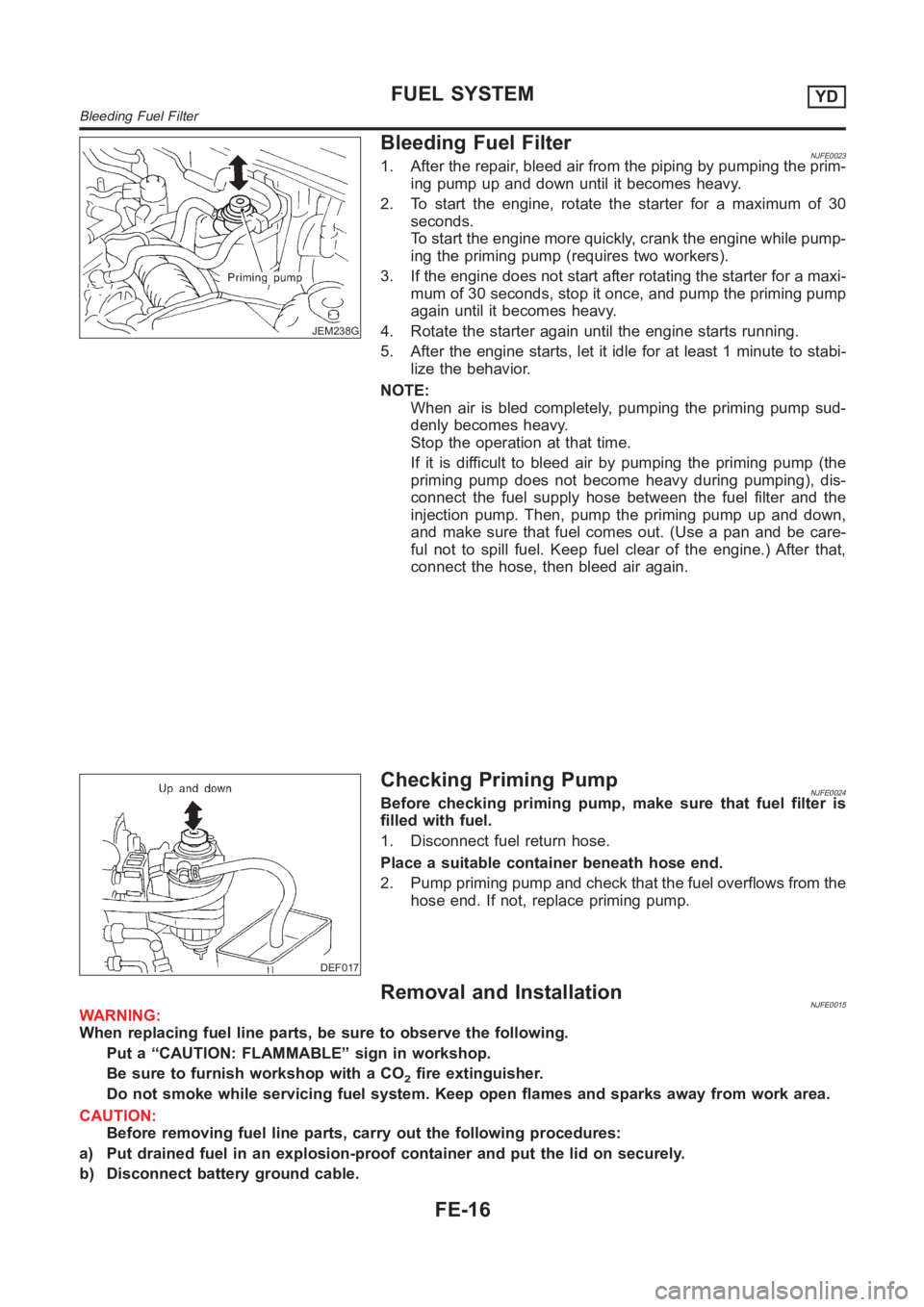
Bleeding Fuel FilterNJFE00231. After the repair, bleed air from the piping by pumping the prim-
ing pump up and down until it becomes heavy.
2. To start the engine, rotate the starter for a maximum of 30
seconds.
To start the engine more quickly, crank the engine while pump-
ing the priming pump (requires two workers).
3. If the engine does not start after rotating the starter for a maxi-
mum of 30 seconds, stop it once, and pump the priming pump
again until it becomes heavy.
4. Rotate the starter again until the engine starts running.
5. After the engine starts, let it idle for at least 1 minute to stabi-
lize the behavior.
NOTE:
When air is bled completely, pumping the priming pump sud-
denly becomes heavy.
Stop the operation at that time.
If it is difficult to bleed air by pumping the priming pump (the
priming pump does not become heavy during pumping), dis-
connect the fuel supply hose between the fuel filter and the
injection pump. Then, pump the priming pump up and down,
and make sure that fuel comes out. (Use a pan and be care-
ful not to spill fuel. Keep fuel clear of the engine.) After that,
connect the hose, then bleed air again.
DEF017
Checking Priming PumpNJFE0024Before checking priming pump, make sure that fuel filter is
filled with fuel.
1. Disconnect fuel return hose.
Place a suitable container beneath hose end.
2. Pump priming pump and check that the fuel overflows from the
hose end. If not, replace priming pump.
Removal and InstallationNJFE0015WARNING:
When replacing fuel line parts, be sure to observe the following.
Put a “CAUTION: FLAMMABLE” sign in workshop.
Be sure to furnish workshop with a CO
2fire extinguisher.
Do not smoke while servicing fuel system. Keep open flames and sparks away from work area.
CAUTION:
Before removing fuel line parts, carry out the following procedures:
a) Put drained fuel in an explosion-proof container and put the lid on securely.
b) Disconnect battery ground cable.
FUEL SYSTEMYD
Bleeding Fuel Filter
FE-16