Page 1123 of 3189
![NISSAN ALMERA N16 2003 Electronic Repair Manual TERMI-
NAL
NO.WIRE
COLORITEM CONDITIONDATA (DC Voltage and Pulse
Signal)
417 PU/R Vehicle speed sensor[Engine is running]
Lift up the vehicle
In 1st gear position
Vehicle speed is 10 km/h (6 MPH)0 - A NISSAN ALMERA N16 2003 Electronic Repair Manual TERMI-
NAL
NO.WIRE
COLORITEM CONDITIONDATA (DC Voltage and Pulse
Signal)
417 PU/R Vehicle speed sensor[Engine is running]
Lift up the vehicle
In 1st gear position
Vehicle speed is 10 km/h (6 MPH)0 - A](/manual-img/5/57350/w960_57350-1122.png)
TERMI-
NAL
NO.WIRE
COLORITEM CONDITIONDATA (DC Voltage and Pulse
Signal)
417 PU/R Vehicle speed sensor[Engine is running]
Lift up the vehicle
In 1st gear position
Vehicle speed is 10 km/h (6 MPH)0 - Approximately 8V
SEF891Y
[Engine is running]
Lift up the vehicle
In 2nd gear position
Vehicle speed is 30 km/h (19 MPH)Approximately 6V
SEF892Y
418 G/ORPark/Neutral position
switch (where fitted)[Ignition switch “ON”]
Gear position is “Neutral”Approximately 0V
[Ignition switch “ON”]
Except the above gear positionBATTERY VOLTAGE
(11 - 14V)
422 B/Y Start signal[Ignition switch “ON”]Approximately 0V
[Ignition switch “START”]BATTERY VOLTAGE
(11 - 14V)
425 P/BAccelerator position sen-
sor ground[Engine is running]
Warm-up condition
Idle speedApproximately 0V
426 BR/RAccelerator position
switch (Idle) ground[Ignition switch “ON”]Approximately 0V
433 G/YAccelerator position sen-
sor power supply[Ignition switch “ON”]Approximately 5V
434 WAccelerator position sen-
sor[Ignition switch “ON”]
Accelerator pedal fully released0.30 - 0.50V
[Ignition switch “ON”]
Accelerator pedal fully depressed3.0 - 4.3V
435 W/GAccelerator position
switch (Idle)[Ignition switch “ON”]
Accelerator pedal fully releasedApproximately 0V
[Ignition switch “ON”]
Accelerator pedal depressedBATTERY VOLTAGE
(11 - 14V)
GI
MA
EM
LC
FE
CL
MT
AT
AX
SU
BR
ST
RS
BT
HA
SC
EL
IDX
TROUBLE DIAGNOSIS — GENERAL DESCRIPTIONYD
ECM Terminals and Reference Value (Cont’d)
EC-69
Page 1124 of 3189
TERMI-
NAL
NO.WIRE
COLORITEM CONDITIONDATA (DC Voltage and Pulse
Signal)
439 L/OR Tachometer[Engine is running]
Warm-up condition
Idle speedApproximately 4.8V
SEF325Y
[Engine is running]
Warm-up condition
Engine speed is 2,000 rpmApproximately 4.6V
SEF326Y
505 OR/L Malfunction indicator[Ignition switch “ON”]Approximately 1V
[Engine is running]
Idle speedBATTERY VOLTAGE
(11 - 14V)
507 W/R Ignition switch[Ignition switch “OFF”]0V
[Ignition switch “ON”]BATTERY VOLTAGE
(11 - 14V)
508 OR Glow lamp[Ignition switch “ON”]
Glow lamp is “ON”Approximately 1V
[Ignition switch “ON”]
Glow lamp is “OFF”BATTERY VOLTAGE
(11 - 14V)
TROUBLE DIAGNOSIS — GENERAL DESCRIPTIONYD
ECM Terminals and Reference Value (Cont’d)
EC-70
Page 1126 of 3189

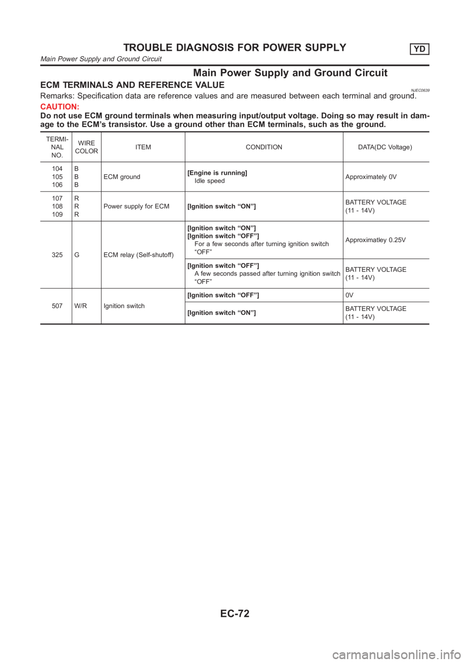
Main Power Supply and Ground Circuit
ECM TERMINALS AND REFERENCE VALUENJEC0639Remarks: Specification data are reference values and are measured between each terminal and ground.
CAUTION:
Do not use ECM ground terminals when measuring input/output voltage. Doing so may result in dam-
age to the ECM’s transistor. Use a ground other than ECM terminals, such as the ground.
TERMI-
NAL
NO.WIRE
COLORITEM CONDITION DATA(DC Voltage)
104
105
106B
B
BECM ground[Engine is running]
Idle speedApproximately 0V
107
108
109R
R
RPower supply for ECM[Ignition switch “ON”]BATTERY VOLTAGE
(11 - 14V)
325 G ECM relay (Self-shutoff)[Ignition switch “ON”]
[Ignition switch “OFF”]
For a few seconds after turning ignition switch
“OFF”Approximatley 0.25V
[Ignition switch “OFF”]
A few seconds passed after turning ignition switch
“OFF”BATTERY VOLTAGE
(11 - 14V)
507 W/R Ignition switch[Ignition switch “OFF”]0V
[Ignition switch “ON”]BATTERY VOLTAGE
(11 - 14V)
TROUBLE DIAGNOSIS FOR POWER SUPPLYYD
Main Power Supply and Ground Circuit
EC-72
Page 1129 of 3189

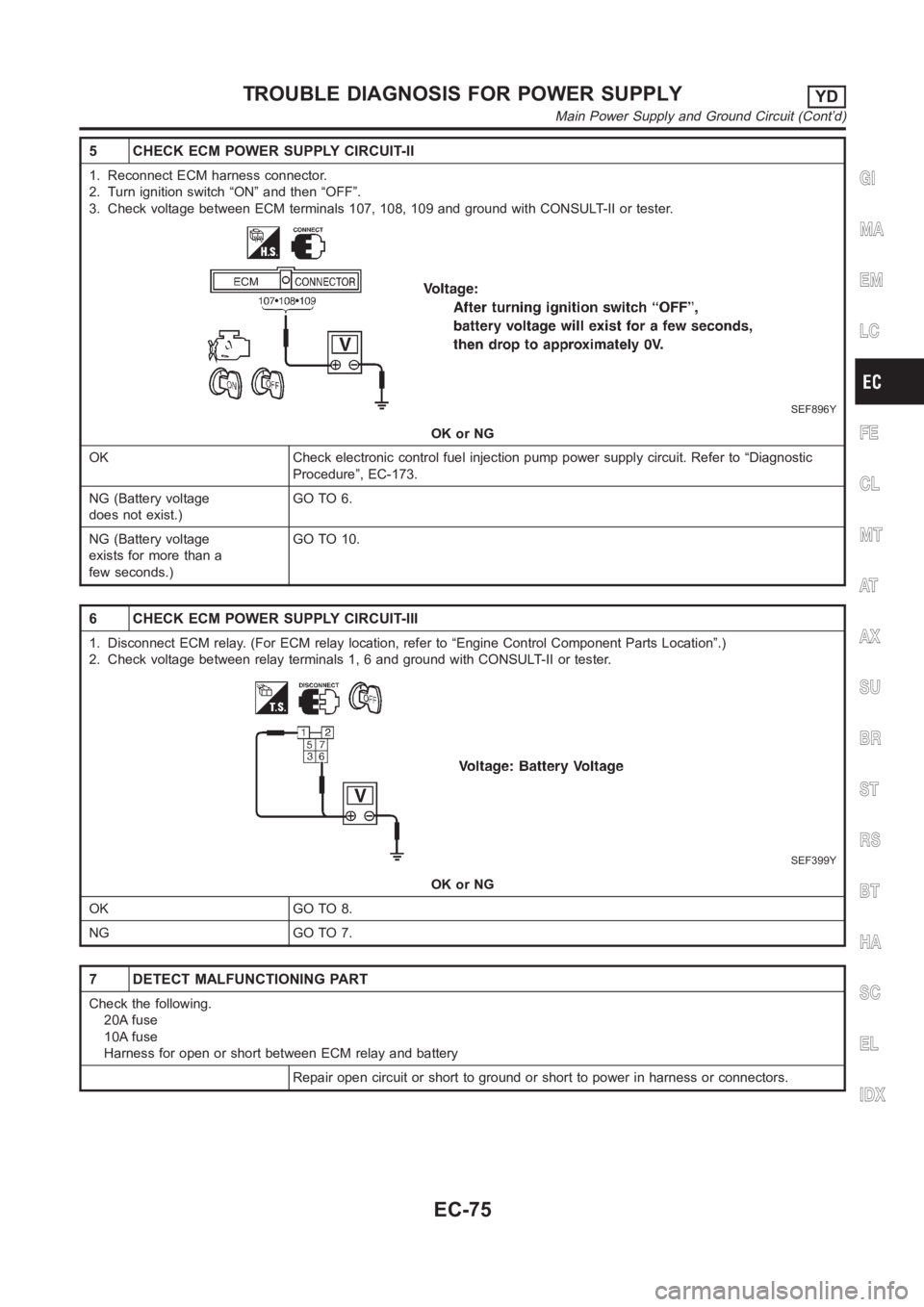
5 CHECK ECM POWER SUPPLY CIRCUIT-II
1. Reconnect ECM harness connector.
2. Turn ignition switch “ON” and then “OFF”.
3. Check voltage between ECM terminals 107, 108, 109 and ground with CONSULT-II or tester.
SEF896Y
OK or NG
OK Check electronic control fuel injection pump power supply circuit. Refer to “Diagnostic
Procedure”, EC-173.
NG (Battery voltage
does not exist.)GO TO 6.
NG (Battery voltage
exists for more than a
few seconds.)GO TO 10.
6 CHECK ECM POWER SUPPLY CIRCUIT-III
1. Disconnect ECM relay. (For ECM relay location, refer to “Engine ControlComponent Parts Location”.)
2. Check voltage between relay terminals 1, 6 and ground with CONSULT-II ortester.
SEF399Y
OK or NG
OK GO TO 8.
NG GO TO 7.
7 DETECT MALFUNCTIONING PART
Check the following.
20A fuse
10A fuse
Harness for open or short between ECM relay and battery
Repair open circuit or short to ground or short to power in harness or connectors.
GI
MA
EM
LC
FE
CL
MT
AT
AX
SU
BR
ST
RS
BT
HA
SC
EL
IDX
TROUBLE DIAGNOSIS FOR POWER SUPPLYYD
Main Power Supply and Ground Circuit (Cont’d)
EC-75
Page 1144 of 3189
![NISSAN ALMERA N16 2003 Electronic Repair Manual TERMI-
NAL
NO.WIRE
COLORITEM CONDITION DATA(DC Voltage)
434 W Accelerator position sensor[Ignition switch “ON”]
Accelerator pedal fully released0.30 - 0.50V
[Ignition switch “ON”]
Accelerator NISSAN ALMERA N16 2003 Electronic Repair Manual TERMI-
NAL
NO.WIRE
COLORITEM CONDITION DATA(DC Voltage)
434 W Accelerator position sensor[Ignition switch “ON”]
Accelerator pedal fully released0.30 - 0.50V
[Ignition switch “ON”]
Accelerator](/manual-img/5/57350/w960_57350-1143.png)
TERMI-
NAL
NO.WIRE
COLORITEM CONDITION DATA(DC Voltage)
434 W Accelerator position sensor[Ignition switch “ON”]
Accelerator pedal fully released0.30 - 0.50V
[Ignition switch “ON”]
Accelerator pedal fully depressed3.0 - 4.3V
435 W/GAccelerator position switch
(Idle)[Ignition switch “ON”]
Accelerator pedal fully releasedApproximately 0V
[Ignition switch “ON”]
Accelerator pedal depressedBATTERY VOLTAGE
(11 - 14V)
On Board Diagnosis LogicNJEC0682This self-diagnosis has the one trip detection logic.
DTC Malfunction is detected when ... Check Items (Possible Cause)
P0120
0403The relation between sensor and switch signals
is not in the nomal range during the specified
accelerator positions.Harness or connectors
(The sensor circuit is open or shorted.)
Accelerator position sensor
Accelerator position switch
SEF817Y
DTC Confirmation ProcedureNJEC0683WITH CONSULT-IINJEC0683S011) Turn ignition switch “ON”.
2) Select “DATA MONITOR” mode with CONSULT-II.
3) Depress and release fully accelerator pedal slowly.
4) If DTC is detected, go to “Diagnostic Procedure”, EC-92.
WITHOUT CONSULT-IINJEC0683S021) Turn ignition switch “ON”.
2) Depress and release fully accelerator pedal slowly.
3) Turn ignition switch “OFF”, wait at least 5 seconds and then
turn “ON”.
4) Perform “Diagnostic Test Mode II (Self-diagnostic results)” with
ECM.
5) If DTC is detected, go to “Diagnostic Procedure”, EC-92.
DTC P0120 ACCEL POS SENSORYD
ECM Terminals and Reference Value (Cont’d)
EC-90
Page 1163 of 3189

SEF893Y
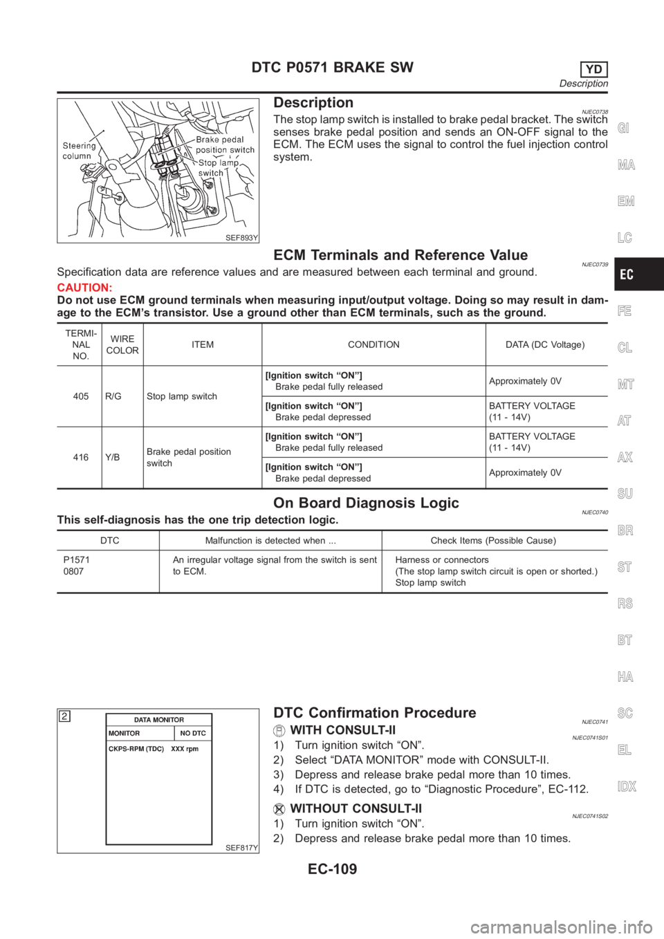
DescriptionNJEC0738The stop lamp switch is installed to brake pedal bracket. The switch
senses brake pedal position and sends an ON-OFF signal to the
ECM. The ECM uses the signal to control the fuel injection control
system.
ECM Terminals and Reference ValueNJEC0739Specification data are reference values and are measured between each terminal and ground.
CAUTION:
Do not use ECM ground terminals when measuring input/output voltage. Doing so may result in dam-
age to the ECM’s transistor. Use a ground other than ECM terminals, such as the ground.
TERMI-
NAL
NO.WIRE
COLORITEM CONDITION DATA (DC Voltage)
405 R/G Stop lamp switch[Ignition switch “ON”]
Brake pedal fully releasedApproximately 0V
[Ignition switch “ON”]
Brake pedal depressedBATTERY VOLTAGE
(11 - 14V)
416 Y/BBrake pedal position
switch[Ignition switch “ON”]
Brake pedal fully releasedBATTERY VOLTAGE
(11 - 14V)
[Ignition switch “ON”]
Brake pedal depressedApproximately 0V
On Board Diagnosis LogicNJEC0740This self-diagnosis has the one trip detection logic.
DTC Malfunction is detected when ... Check Items (Possible Cause)
P1571
0807An irregular voltage signal from the switch is sent
to ECM.Harness or connectors
(The stop lamp switch circuit is open or shorted.)
Stop lamp switch
SEF817Y
DTC Confirmation ProcedureNJEC0741WITH CONSULT-IINJEC0741S011) Turn ignition switch “ON”.
2) Select “DATA MONITOR” mode with CONSULT-II.
3) Depress and release brake pedal more than 10 times.
4) If DTC is detected, go to “Diagnostic Procedure”, EC-112.
WITHOUT CONSULT-IINJEC0741S021) Turn ignition switch “ON”.
2) Depress and release brake pedal more than 10 times.
GI
MA
EM
LC
FE
CL
MT
AT
AX
SU
BR
ST
RS
BT
HA
SC
EL
IDX
DTC P0571 BRAKE SWYD
Description
EC-109
Page 1184 of 3189

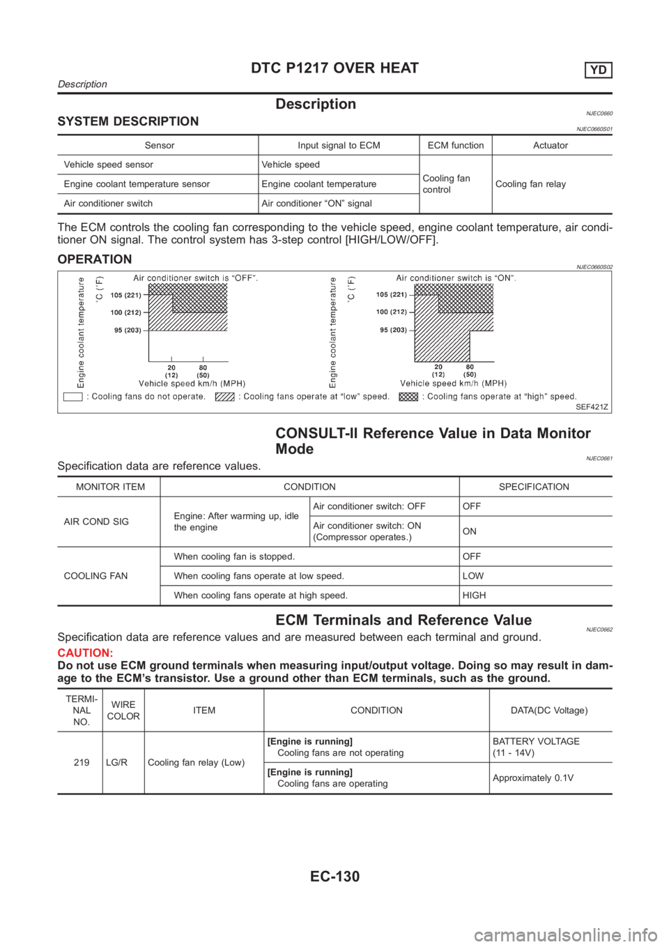
DescriptionNJEC0660SYSTEM DESCRIPTIONNJEC0660S01
Sensor Input signal to ECM ECM function Actuator
Vehicle speed sensor Vehicle speed
Cooling fan
controlCooling fan relay Engine coolant temperature sensor Engine coolant temperature
Air conditioner switch Air conditioner “ON” signal
The ECM controls the cooling fan corresponding to the vehicle speed, engine coolant temperature, air condi-
tioner ON signal. The control system has 3-step control [HIGH/LOW/OFF].
OPERATIONNJEC0660S02
SEF421Z
CONSULT-II Reference Value in Data Monitor
Mode
NJEC0661Specification data are reference values.
MONITOR ITEM CONDITION SPECIFICATION
AIRCONDSIGEngine: After warming up, idle
the engineAir conditioner switch: OFF OFF
Air conditioner switch: ON
(Compressor operates.)ON
COOLING FANWhen cooling fan is stopped. OFF
When cooling fans operate at low speed. LOW
When cooling fans operate at high speed. HIGH
ECM Terminals and Reference ValueNJEC0662Specification data are reference values and are measured between each terminal and ground.
CAUTION:
Do not use ECM ground terminals when measuring input/output voltage. Doing so may result in dam-
age to the ECM’s transistor. Use a ground other than ECM terminals, such as the ground.
TERMI-
NAL
NO.WIRE
COLORITEM CONDITION DATA(DC Voltage)
219 LG/R Cooling fan relay (Low)[Engine is running]
Cooling fans are not operatingBATTERY VOLTAGE
(11 - 14V)
[Engine is running]
Cooling fans are operatingApproximately 0.1V
DTC P1217 OVER HEATYD
Description
EC-130
Page 1185 of 3189
![NISSAN ALMERA N16 2003 Electronic Repair Manual TERMI-
NAL
NO.WIRE
COLORITEM CONDITION DATA(DC Voltage)
221 LG/B Cooling fan relay (High)[Engine is running]
Cooling fans are not operating
Cooling fans are operating at low speedBATTERY VOLTAGE
(11 - NISSAN ALMERA N16 2003 Electronic Repair Manual TERMI-
NAL
NO.WIRE
COLORITEM CONDITION DATA(DC Voltage)
221 LG/B Cooling fan relay (High)[Engine is running]
Cooling fans are not operating
Cooling fans are operating at low speedBATTERY VOLTAGE
(11 -](/manual-img/5/57350/w960_57350-1184.png)
TERMI-
NAL
NO.WIRE
COLORITEM CONDITION DATA(DC Voltage)
221 LG/B Cooling fan relay (High)[Engine is running]
Cooling fans are not operating
Cooling fans are operating at low speedBATTERY VOLTAGE
(11 - 14V)
[Engine is running]
Cooling fans are operating at high speedApproximately 0.1V
On Board Diagnosis LogicNJEC0663This diagnosis continuously monitors the engine coolant temperature.
If the cooling fan or another component in the cooling system malfunctions, engine coolant temperature will
rise.
When the engine coolant temperature reaches an abnormally high temperature condition, a malfunction is
indicated.
This self-diagnosis has the one trip detection logic.
DTC Malfunction is detected when ... Check Items (Possible Cause)
P1217
0208Cooling fan does not operate properly (Overheat).
Cooling fan system does not operate properly
(Overheat).
Engine coolant was not added to the system using
the proper filling method.Harness or connectors
(The cooling fan circuit is open or shorted.)
Cooling fan
Radiator hose
Radiator
Radiator cap
Water pump
Thermostat
Engine coolant temperature sensor
For more information, refer to “MAIN 12 CAUSES OF
OVERHEATING”, EC-144.
CAUTION:
When a malfunction is indicated, be sure to replace the coolant following the procedure in the LC-43,
“Changing Engine Coolant”. Also, replace the engine oil.
1) Fill radiator with coolant up to specified level with a filling speed of 2liters per minute. Be sure
to use coolant with the proper mixture ratio. Refer to MA-21, “Engine Coolant Mixture Ratio”.
2) After refilling coolant, run engine to ensure that no water-flow noise is emitted.
GI
MA
EM
LC
FE
CL
MT
AT
AX
SU
BR
ST
RS
BT
HA
SC
EL
IDX
DTC P1217 OVER HEATYD
ECM Terminals and Reference Value (Cont’d)
EC-131