Page 1122 of 3189
![NISSAN ALMERA N16 2003 Electronic Repair Manual TERMI-
NAL
NO.WIRE
COLORITEM CONDITIONDATA (DC Voltage and Pulse
Signal)
337
338
350
351W/L
PU/W
GY
OR/BEGR volume control
valve[Engine is running]
Warm-up condition
Idle speed0.1 - 14V
(Voltage signa NISSAN ALMERA N16 2003 Electronic Repair Manual TERMI-
NAL
NO.WIRE
COLORITEM CONDITIONDATA (DC Voltage and Pulse
Signal)
337
338
350
351W/L
PU/W
GY
OR/BEGR volume control
valve[Engine is running]
Warm-up condition
Idle speed0.1 - 14V
(Voltage signa](/manual-img/5/57350/w960_57350-1121.png)
TERMI-
NAL
NO.WIRE
COLORITEM CONDITIONDATA (DC Voltage and Pulse
Signal)
337
338
350
351W/L
PU/W
GY
OR/BEGR volume control
valve[Engine is running]
Warm-up condition
Idle speed0.1 - 14V
(Voltage signals of each ECM
terminals differ according to the
control position of EGR volume
control valve.)
344 WCrankshaft position sen-
sor (TDC)[Engine is running]
Warm-up condition
Idle speedApproximately 0V
SEF333Y
[Engine is running]
Warm-up condition
Engine speed is 2,000 rpmApproximately 0V
SEF334Y
347 L/BEngine coolant tempera-
ture sensor[Engine is running]Approximately 0 - 4.8V
Output voltage varies with
engine coolant temperature
403 R/L Air conditioner switch[Engine is running]
Air conditioner switch is “OFF”BATTERY VOLTAGE
(11 - 14V)
[Engine is running]
Both air conditioner switch and blower fan
switch are “ON”
(Compressor is operating)Approximately 0.1V
405 R/G Stop lamp switch[Ignition switch “ON”]
Brake pedal fully releasedApproximately 0V
[Ignition switch “ON”]
Brake pedal depressedBATTERY VOLTAGE
(11 - 14V)
416 Y/BBrake pedal position
switch[Ignition switch “ON”]
Brake pedal fully releasedBATTERY VOLTAGE
(11 - 14V)
[Ignition switch “ON”]
Brake pedal depressedApproximately 0V
TROUBLE DIAGNOSIS — GENERAL DESCRIPTIONYD
ECM Terminals and Reference Value (Cont’d)
EC-68
Page 1153 of 3189
SEF420Z
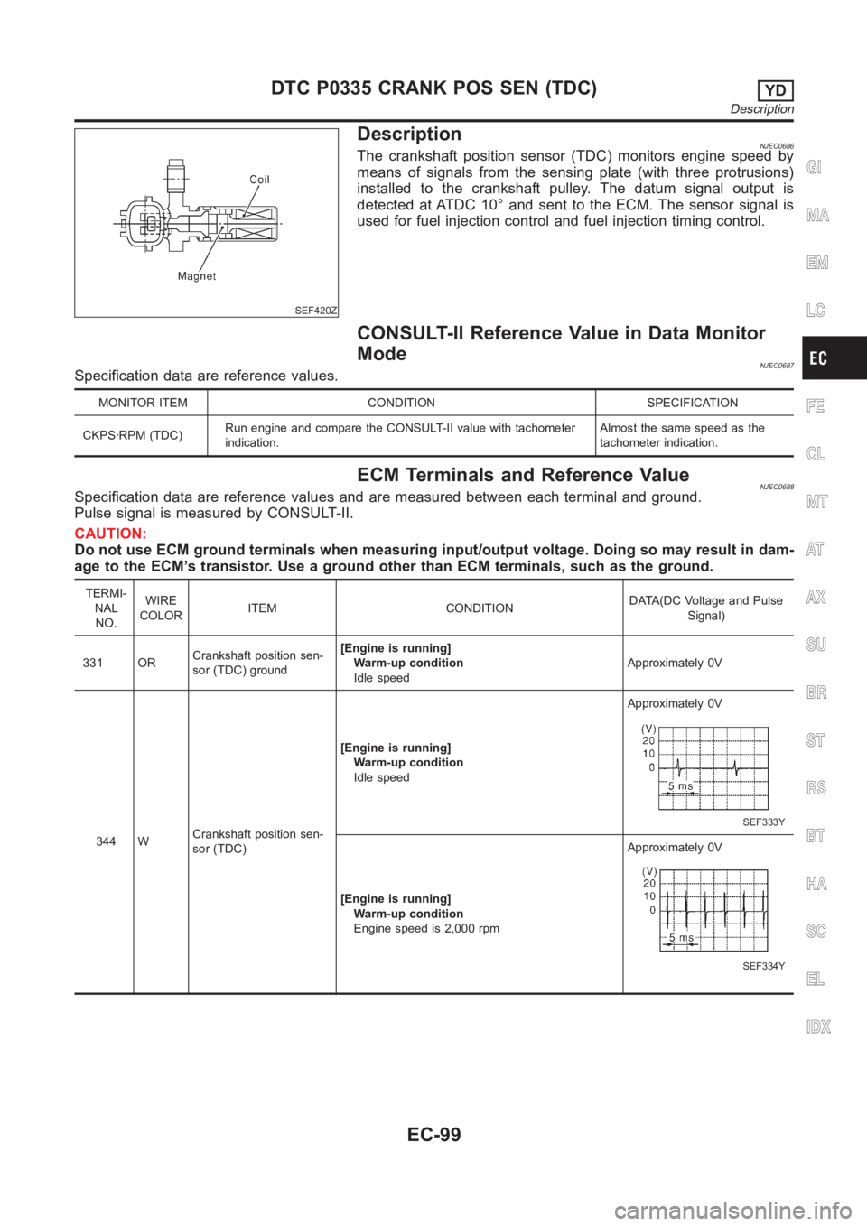
DescriptionNJEC0686The crankshaft position sensor (TDC) monitors engine speed by
means of signals from the sensing plate (with three protrusions)
installed to the crankshaft pulley. The datum signal output is
detected at ATDC 10° and sent to the ECM. The sensor signal is
used for fuel injection control and fuel injection timing control.
CONSULT-II Reference Value in Data Monitor
Mode
NJEC0687Specification data are reference values.
MONITOR ITEM CONDITION SPECIFICATION
CKPS·RPM (TDC)Run engine and compare the CONSULT-II value with tachometer
indication.Almost the same speed as the
tachometer indication.
ECM Terminals and Reference ValueNJEC0688Specification data are reference values and are measured between each terminal and ground.
Pulse signal is measured by CONSULT-II.
CAUTION:
Do not use ECM ground terminals when measuring input/output voltage. Doing so may result in dam-
age to the ECM’s transistor. Use a ground other than ECM terminals, such as the ground.
TERMI-
NAL
NO.WIRE
COLORITEM CONDITIONDATA(DC Voltage and Pulse
Signal)
331 ORCrankshaft position sen-
sor (TDC) ground[Engine is running]
Warm-up condition
Idle speedApproximately 0V
344 WCrankshaft position sen-
sor (TDC)[Engine is running]
Warm-up condition
Idle speedApproximately 0V
SEF333Y
[Engine is running]
Warm-up condition
Engine speed is 2,000 rpmApproximately 0V
SEF334Y
GI
MA
EM
LC
FE
CL
MT
AT
AX
SU
BR
ST
RS
BT
HA
SC
EL
IDX
DTC P0335 CRANK POS SEN (TDC)YD
Description
EC-99
Page 1154 of 3189
On Board Diagnosis Logic=NJEC0689This self-diagnosis has the one trip detection logic.
DTC Malfunction is detected when ... Check Items (Possible Cause)
P0335
0407An improper signal from the sensor is sent to
ECM during engine running and cranking.Harness or connectors
(The sensor circuit is open.)
Crankshaft position sensor (TDC)
SEF817Y
DTC Confirmation ProcedureNJEC0690Before performing the following procedure, confirm that bat-
tery voltage is more than 10V.
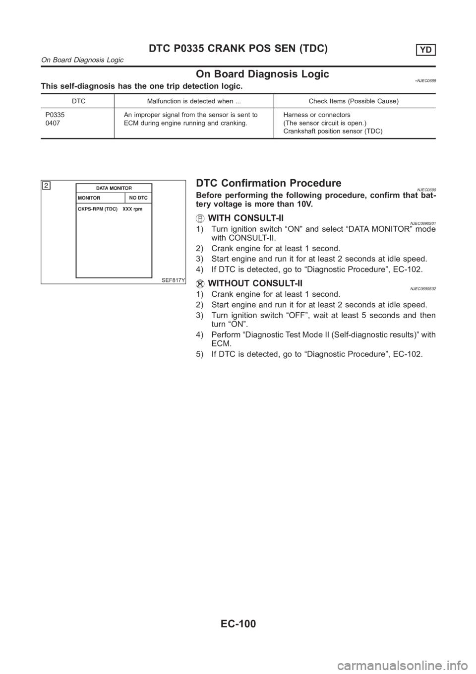
WITH CONSULT-IINJEC0690S011) Turn ignition switch “ON” and select “DATA MONITOR” mode
with CONSULT-II.
2) Crank engine for at least 1 second.
3) Start engine and run it for at least 2 seconds at idle speed.
4) If DTC is detected, go to “Diagnostic Procedure”, EC-102.
WITHOUT CONSULT-IINJEC0690S021) Crank engine for at least 1 second.
2) Start engine and run it for at least 2 seconds at idle speed.
3) Turn ignition switch “OFF”, wait at least 5 seconds and then
turn “ON”.
4) Perform “Diagnostic Test Mode II (Self-diagnostic results)” with
ECM.
5) If DTC is detected, go to “Diagnostic Procedure”, EC-102.
DTC P0335 CRANK POS SEN (TDC)YD
On Board Diagnosis Logic
EC-100
Page 1156 of 3189
Diagnostic ProcedureNJEC0692
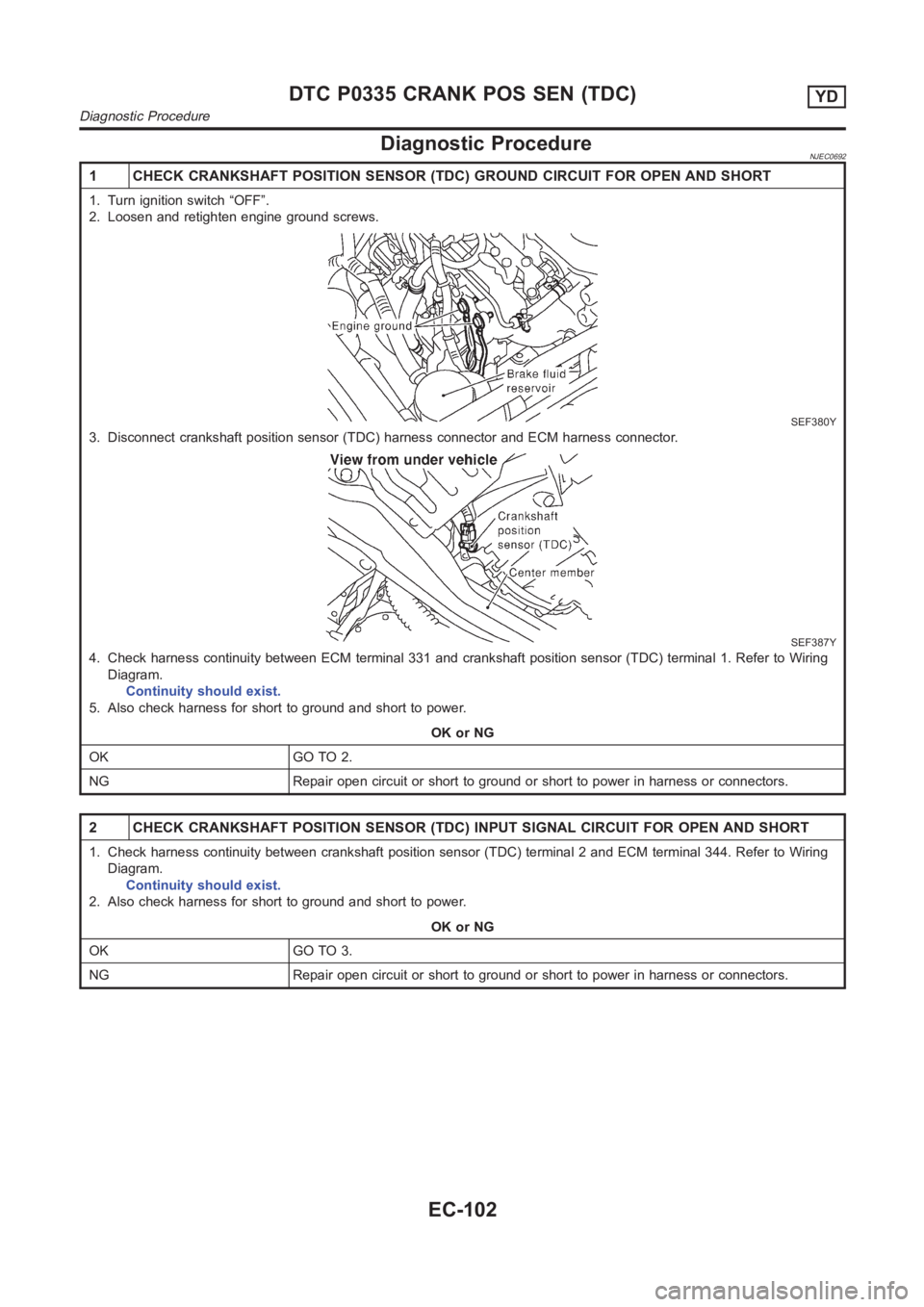
1 CHECK CRANKSHAFT POSITION SENSOR (TDC) GROUND CIRCUIT FOR OPEN AND SHORT
1. Turn ignition switch “OFF”.
2. Loosen and retighten engine ground screws.
SEF380Y
3. Disconnect crankshaft position sensor (TDC) harness connector and ECMharness connector.
SEF387Y
4. Check harness continuity between ECM terminal 331 and crankshaft position sensor (TDC) terminal 1. Refer to Wiring
Diagram.
Continuity should exist.
5. Also check harness for short to ground and short to power.
OK or NG
OK GO TO 2.
NG Repair open circuit or short to ground or short to power in harness or connectors.
2 CHECK CRANKSHAFT POSITION SENSOR (TDC) INPUT SIGNAL CIRCUIT FOR OPEN ANDSHORT
1. Check harness continuity between crankshaft position sensor (TDC) terminal 2 and ECM terminal 344. Refer to Wiring
Diagram.
Continuity should exist.
2. Also check harness for short to ground and short to power.
OK or NG
OK GO TO 3.
NG Repair open circuit or short to ground or short to power in harness or connectors.
DTC P0335 CRANK POS SEN (TDC)YD
Diagnostic Procedure
EC-102
Page 1157 of 3189
3 CHECK CRANKSHAFT POSITION SENSOR (TDC)-I
1. Loosen the fixing bolt and remove the crankshaft position sensor (TDC).
2. Visually check the sensor for chipping.
SEF620S
OK or NG
OK GO TO 4.
NG Replace crankshaft position sensor (TDC).
4 CHECK CRANKSHAFT POSITION SENSOR (TDC)-II
1. Disconnect crankshaft position sensor (TDC) harness connector.
2. Check resistance between crankshaft position sensor (TDC) terminals 1and 2.
SEF408Y
OK or NG
OK GO TO 5.
NG Replace crankshaft position sensor (TDC).
GI
MA
EM
LC
FE
CL
MT
AT
AX
SU
BR
ST
RS
BT
HA
SC
EL
IDX
DTC P0335 CRANK POS SEN (TDC)YD
Diagnostic Procedure (Cont’d)
EC-103
Page 1158 of 3189
5 INSTALL CRANKSHAFT POSITION SENSOR (TDC)
1. Install crankshaft position sensor (TDC) and temporarily tighten the fixing bolt.
2. Turn crankshaft position sensor (TDC) clockwise until it stops.
3. Tighten the fixing bolt.
SEF409Y
GO TO 6.
6 CHECK INTERMITTENT INCIDENT
Refer to “TROUBLE DIAGNOSIS FOR INTERMITTENT INCIDENT”, EC-71.
INSPECTION END
DTC P0335 CRANK POS SEN (TDC)YD
Diagnostic Procedure (Cont’d)
EC-104
Page 1242 of 3189
DescriptionNJEC0760SYSTEM DESCRIPTIONNJEC0760S01
Sensor Input Signal to ECMECM
Func-
tionActuator
Crankshaft position sensor
(TDC)Engine speed
Glow
controlGlow lamp,
Glow relay
"
Glow plugs Engine coolant tempera-
ture sensorEngine coolant tem-
perature
When engine coolant temperature is more than approximately
75°C (167°F), the glow relay turns off.
When coolant temperature is lower than approximately 75°C
(167°F):
Ignition switch ON
After ignition switch has turned to ON, the glow relay turns ON
for a certain period of time in relation to engine coolant
temperature, allowing current to flow through glow plug.
Cranking
The glow relay turns ON, allowing current to flow through glow
plug.
Starting
After engine has started, current continues to flow through
glow plug (after-glow mode) for a certain period in relation to
engine coolant temperature.
The glow indicator lamp turns ON for a certain period of time in
relation to engine cooalnt temperature at the time glow relay is
turned ON.
SEF376Y
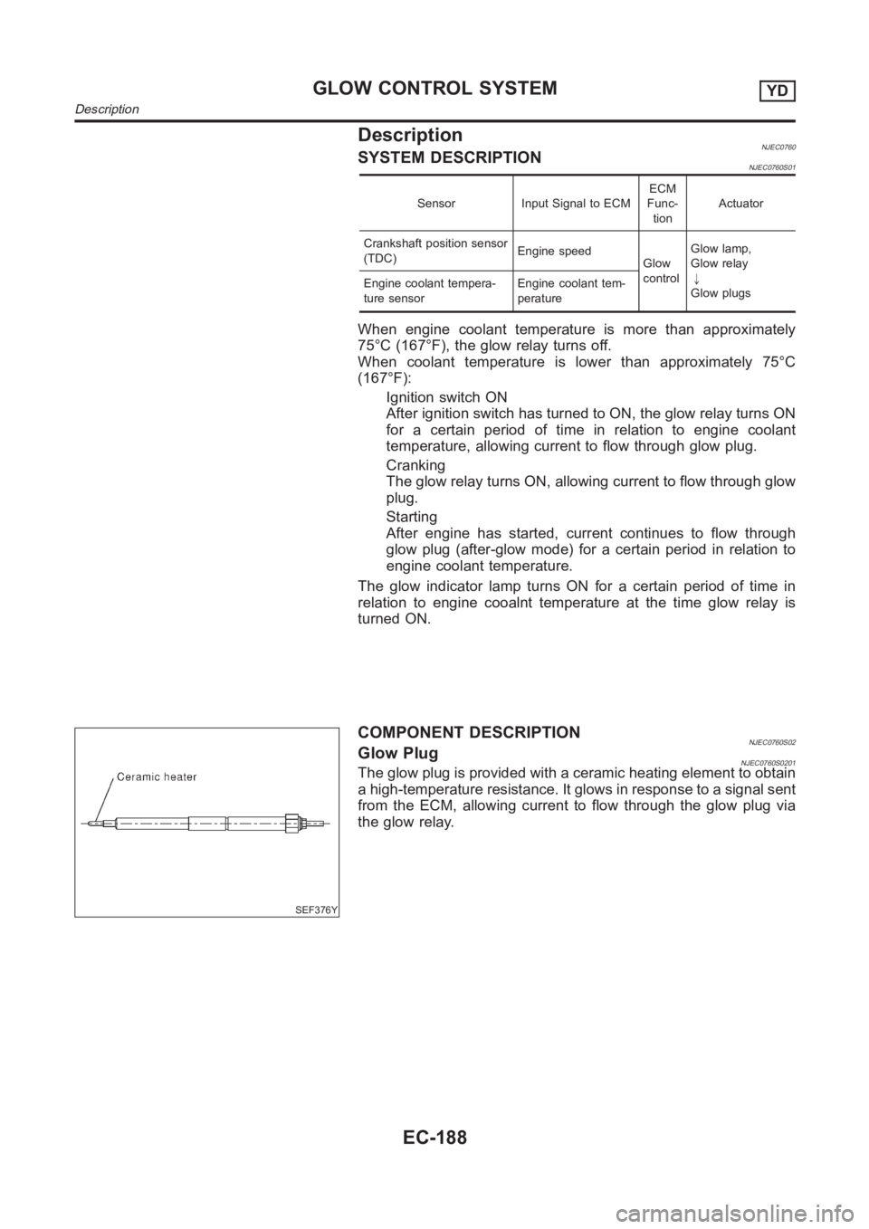
COMPONENT DESCRIPTIONNJEC0760S02Glow PlugNJEC0760S0201The glow plug is provided with a ceramic heating element to obtain
a high-temperature resistance. It glows in response to a signal sent
from the ECM, allowing current to flow through the glow plug via
the glow relay.
GLOW CONTROL SYSTEMYD
Description
EC-188
Page 1251 of 3189
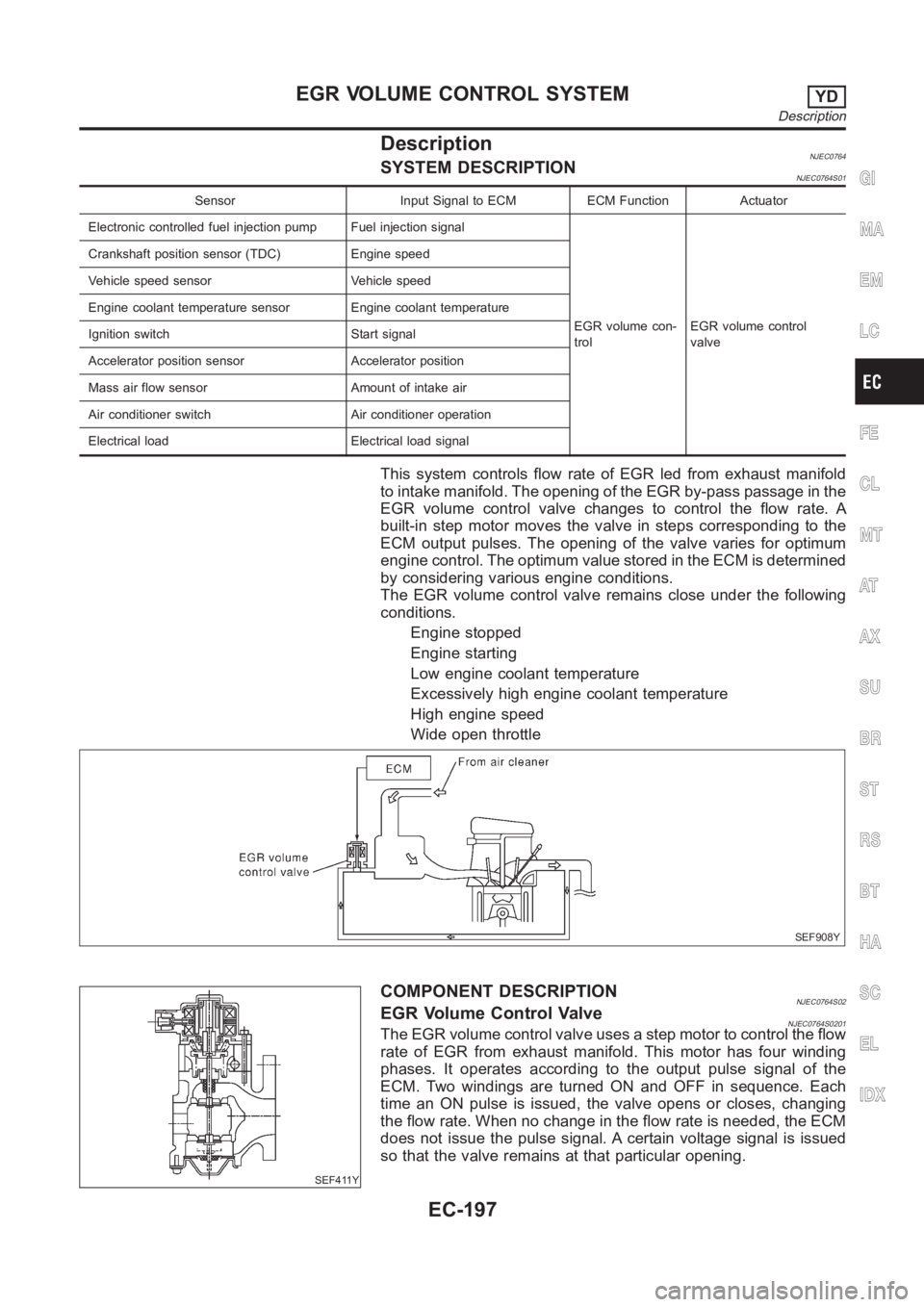
DescriptionNJEC0764SYSTEM DESCRIPTIONNJEC0764S01
Sensor Input Signal to ECM ECM Function Actuator
Electronic controlled fuel injection pump Fuel injection signal
EGR volume con-
trolEGR volume control
valve Crankshaft position sensor (TDC) Engine speed
Vehicle speed sensor Vehicle speed
Engine coolant temperature sensor Engine coolant temperature
Ignition switch Start signal
Accelerator position sensor Accelerator position
Mass air flow sensor Amount of intake air
Air conditioner switch Air conditioner operation
Electrical load Electrical load signal
This system controls flow rate of EGR led from exhaust manifold
to intake manifold. The opening of the EGR by-pass passage in the
EGR volume control valve changes to control the flow rate. A
built-in step motor moves the valve in steps corresponding to the
ECM output pulses. The opening of the valve varies for optimum
engine control. The optimum value stored in the ECM is determined
by considering various engine conditions.
The EGR volume control valve remains close under the following
conditions.
Engine stopped
Engine starting
Low engine coolant temperature
Excessively high engine coolant temperature
High engine speed
Wide open throttle
SEF908Y
SEF411Y
COMPONENT DESCRIPTIONNJEC0764S02EGR Volume Control ValveNJEC0764S0201The EGR volume control valve uses a step motor to control the flow
rate of EGR from exhaust manifold. This motor has four winding
phases. It operates according to the output pulse signal of the
ECM. Two windings are turned ON and OFF in sequence. Each
time an ON pulse is issued, the valve opens or closes, changing
the flow rate. When no change in the flow rate is needed, the ECM
does not issue the pulse signal. A certain voltage signal is issued
so that the valve remains at that particular opening.
GI
MA
EM
LC
FE
CL
MT
AT
AX
SU
BR
ST
RS
BT
HA
SC
EL
IDX
EGR VOLUME CONTROL SYSTEMYD
Description
EC-197