2003 NISSAN ALMERA N16 crankshaft
[x] Cancel search: crankshaftPage 1268 of 3189
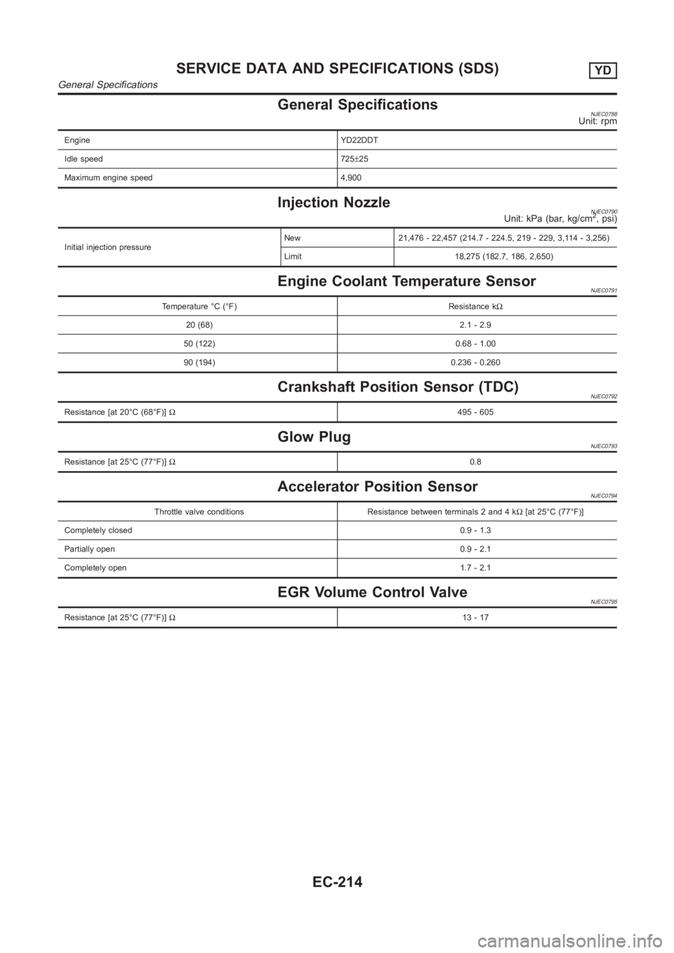
General SpecificationsNJEC0788Unit: rpm
Engine YD22DDT
Idle speed 725±25
Maximum engine speed 4,900
Injection NozzleNJEC0790Unit: kPa (bar, kg/cm2, psi)
Initial injection pressureNew 21,476 - 22,457 (214.7 - 224.5, 219 - 229, 3,114 - 3,256)
Limit 18,275 (182.7, 186, 2,650)
Engine Coolant Temperature SensorNJEC0791
Temperature °C (°F) Resistance kΩ
20 (68) 2.1 - 2.9
50 (122) 0.68 - 1.00
90 (194) 0.236 - 0.260
Crankshaft Position Sensor (TDC)NJEC0792
Resistance [at 20°C (68°F)]Ω495 - 605
Glow PlugNJEC0793
Resistance [at 25°C (77°F)]Ω0.8
Accelerator Position SensorNJEC0794
Throttle valve conditions Resistance between terminals 2 and 4 kΩ[at 25°C (77°F)]
Completely closed0.9 - 1.3
Partially open0.9 - 2.1
Completely open1.7 - 2.1
EGR Volume Control ValveNJEC0795
Resistance [at 25°C (77°F)]Ω13 - 17
SERVICE DATA AND SPECIFICATIONS (SDS)YD
General Specifications
EC-214
Page 1343 of 3189
NJMT0008
SMT928D
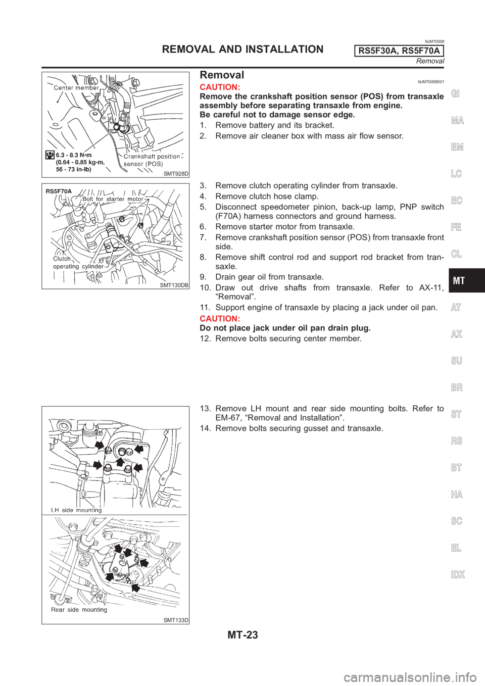
RemovalNJMT0008S01CAUTION:
Remove the crankshaft position sensor (POS) from transaxle
assembly before separating transaxle from engine.
Be careful not to damage sensor edge.
1. Remove battery and its bracket.
2. Remove air cleaner box with mass air flow sensor.
SMT130DB
3. Remove clutch operating cylinder from transaxle.
4. Remove clutch hose clamp.
5. Disconnect speedometer pinion, back-up lamp, PNP switch
(F70A) harness connectors and ground harness.
6. Remove starter motor from transaxle.
7. Remove crankshaft position sensor (POS) from transaxle front
side.
8. Remove shift control rod and support rod bracket from tran-
saxle.
9. Drain gear oil from transaxle.
10. Draw out drive shafts from transaxle. Refer to AX-11,
“Removal”.
11. Support engine of transaxle by placing a jack under oil pan.
CAUTION:
Do not place jack under oil pan drain plug.
12. Remove bolts securing center member.
SMT133D
13. Remove LH mount and rear side mounting bolts. Refer to
EM-67, “Removal and Installation”.
14. Remove bolts securing gusset and transaxle.
GI
MA
EM
LC
EC
FE
CL
AT
AX
SU
BR
ST
RS
BT
HA
SC
EL
IDX
REMOVAL AND INSTALLATIONRS5F30A, RS5F70A
Removal
MT-23
Page 1346 of 3189
NJMT0090
SMT928D
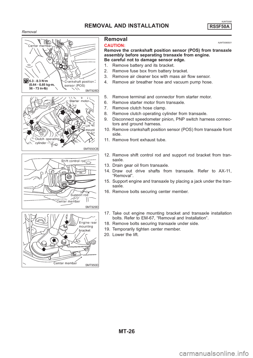
RemovalNJMT0090S01CAUTION:
Remove the crankshaft position sensor (POS) from transaxle
assembly before separating transaxle from engine.
Be careful not to damage sensor edge.
1. Remove battery and its bracket.
2. Remove fuse box from battery bracket.
3. Remove air cleaner box with mass air flow sensor.
4. Remove air breather hose and vacuum pump hose.
SMT650CB
5. Remove terminal and connector from starter motor.
6. Remove starter motor from transaxle.
7. Remove clutch hose clamp.
8. Remove clutch operating cylinder from transaxle.
9. Disconnect speedometer pinion, PNP switch harness connec-
tors and ground harness.
10. Remove crankshaft position sensor (POS) from transaxle front
side.
11. Remove front exhaust tube.
SMT929D
12. Remove shift control rod and support rod bracket from tran-
saxle.
13. Drain gear oil from transaxle.
14. Draw out drive shafts from transaxle. Refer to AX-11,
“Removal”.
15. Support engine and transaxle by placing a jack under the tran-
saxle.
16. Remove bolts securing center member.
SMT950D
17. Take out engine mounting bracket and transaxle installation
bolts. Refer to EM-67, “Removal and Installation”.
18. Remove bolts securing transaxle under side.
19. Temporarily tighten center member.
20. Lower the lift.
REMOVAL AND INSTALLATIONRS5F50A
Removal
MT-26
Page 1463 of 3189
PRECAUTIONS
AT-7
D
E
F
G
H
I
J
K
L
MA
B
AT
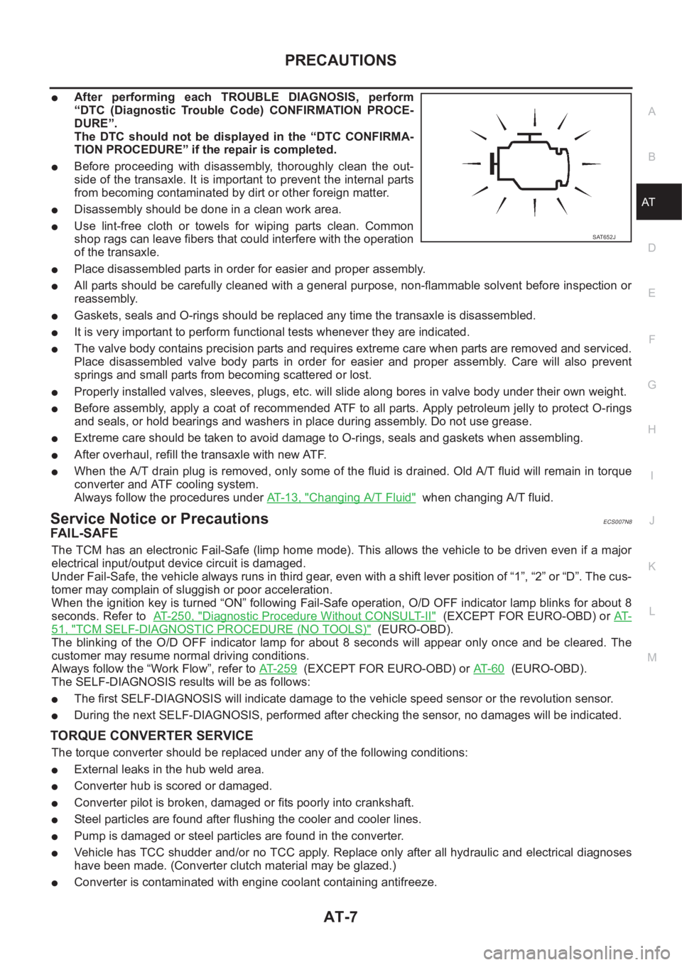
●After performing each TROUBLE DIAGNOSIS, perform
“DTC (Diagnostic Trouble Code) CONFIRMATION PROCE-
DURE”.
The DTC should not be displayed in the “DTC CONFIRMA-
TION PROCEDURE” if the repair is completed.
●Before proceeding with disassembly, thoroughly clean the out-
side of the transaxle. It is important to prevent the internal parts
from becoming contaminated by dirt or other foreign matter.
●Disassembly should be done in a clean work area.
●Use lint-free cloth or towels for wiping parts clean. Common
shop rags can leave fibers that could interfere with the operation
of the transaxle.
●Place disassembled parts in order for easier and proper assembly.
●All parts should be carefully cleaned with a general purpose, non-flammable solvent before inspection or
reassembly.
●Gaskets, seals and O-rings should be replaced any time the transaxle is disassembled.
●It is very important to perform functional tests whenever they are indicated.
●The valve body contains precision parts and requires extreme care when parts are removed and serviced.
Place disassembled valve body parts in order for easier and proper assembly. Care will also prevent
springs and small parts from becoming scattered or lost.
●Properly installed valves, sleeves, plugs, etc. will slide along bores in valve body under their own weight.
●Before assembly, apply a coat of recommended ATF to all parts. Apply petroleum jelly to protect O-rings
and seals, or hold bearings and washers in place during assembly. Do not use grease.
●Extreme care should be taken to avoid damage to O-rings, seals and gaskets when assembling.
●After overhaul, refill the transaxle with new ATF.
●When the A/T drain plug is removed, only some of the fluid is drained. Old A/T fluid will remain in torque
converter and ATF cooling system.
Always follow the procedures under AT-13, "
Changing A/T Fluid" when changing A/T fluid.
Service Notice or PrecautionsECS007N8
FA I L - S A F E
The TCM has an electronic Fail-Safe (limp home mode). This allows the vehicle to be driven even if a major
electrical input/output device circuit is damaged.
Under Fail-Safe, the vehicle always runs in third gear, even with a shift lever position of “1”, “2” or “D”. The cus-
tomer may complain of sluggish or poor acceleration.
When the ignition key is turned “ON” following Fail-Safe operation, O/D OFF indicator lamp blinks for about 8
seconds. Refer to AT- 2 5 0 , "
Diagnostic Procedure Without CONSULT-II" (EXCEPT FOR EURO-OBD) or AT-
51, "TCM SELF-DIAGNOSTIC PROCEDURE (NO TOOLS)" (EURO-OBD).
The blinking of the O/D OFF indicator lamp for about 8 seconds will appear only once and be cleared. The
customer may resume normal driving conditions.
Always follow the “Work Flow”, refer to AT- 2 5 9
(EXCEPT FOR EURO-OBD) or AT- 6 0 (EURO-OBD).
The SELF-DIAGNOSIS results will be as follows:
●The first SELF-DIAGNOSIS will indicate damage to the vehicle speed sensor or the revolution sensor.
●During the next SELF-DIAGNOSIS, performed after checking the sensor, no damages will be indicated.
TORQUE CONVERTER SERVICE
The torque converter should be replaced under any of the following conditions:
●External leaks in the hub weld area.
●Converter hub is scored or damaged.
●Converter pilot is broken, damaged or fits poorly into crankshaft.
●Steel particles are found after flushing the cooler and cooler lines.
●Pump is damaged or steel particles are found in the converter.
●Vehicle has TCC shudder and/or no TCC apply. Replace only after all hydraulic and electrical diagnoses
have been made. (Converter clutch material may be glazed.)
●Converter is contaminated with engine coolant containing antifreeze.
SAT652J
Page 1866 of 3189
![NISSAN ALMERA N16 2003 Electronic Repair Manual AT-410
[ALL]
REMOVAL AND INSTALLATION
REMOVAL AND INSTALLATION
PFP:00000
RemovalECS007T4
CAUTION:
Before separating transaxle from engine, remove the crankshaft
position sensor (OBD) from transaxle. B NISSAN ALMERA N16 2003 Electronic Repair Manual AT-410
[ALL]
REMOVAL AND INSTALLATION
REMOVAL AND INSTALLATION
PFP:00000
RemovalECS007T4
CAUTION:
Before separating transaxle from engine, remove the crankshaft
position sensor (OBD) from transaxle. B](/manual-img/5/57350/w960_57350-1865.png)
AT-410
[ALL]
REMOVAL AND INSTALLATION
REMOVAL AND INSTALLATION
PFP:00000
RemovalECS007T4
CAUTION:
Before separating transaxle from engine, remove the crankshaft
position sensor (OBD) from transaxle. Be careful not to damage
sensor.
1. Remove battery and bracket.
2. Remove air duct between throttle body and air cleaner.
3. Disconnect A/T solenoid harness connector, PNP switch har-
ness connector and revolution sensor harness connector.
4. Remove crankshaft position sensor (OBD) from transaxle.
5. Drain ATF from transaxle.
6. Disconnect control cable from transaxle.
7. Disconnect fluid cooler hoses.
8. Remove drive shafts. Refer to AX-10, "FRONT DRIVE SHAFT".
9. Remove the intake manifold support bracket. Refer to EM-16,
"INTAKE MANIFOLD" .
10. Remove starter motor from transaxle.
11. Remove upper bolts fixing transaxle to engine.
12. Support transaxle with a jack.
13. Remove center member.
●Tighten center member fixing bolts to specified torque, Refer
to EM-67, "
ENGINE ASSEMBLY" .
14. Remove center member, engine insulator and engine mounting bracket.
●Tighten center member fixing bolts to specified torque, Refer to EM-67, "ENGINE ASSEMBLY" .
SAT501HA
Tighten bolts to specified torque.
: 41 - 52 N-m (4.2 - 5.3 kg-m, 30 - 38 ft-lb)
SAT304G
AAT469
Page 1867 of 3189
![NISSAN ALMERA N16 2003 Electronic Repair Manual REMOVAL AND INSTALLATION
AT-411
[ALL]
D
E
F
G
H
I
J
K
L
MA
B
AT
15. Remove suspension member. Refer to SU-5, "FRONTSUSPEN-
SION MEMBER".
16. Remove dust cover from converter housing.
Rotate cr NISSAN ALMERA N16 2003 Electronic Repair Manual REMOVAL AND INSTALLATION
AT-411
[ALL]
D
E
F
G
H
I
J
K
L
MA
B
AT
15. Remove suspension member. Refer to SU-5, "FRONTSUSPEN-
SION MEMBER".
16. Remove dust cover from converter housing.
Rotate cr](/manual-img/5/57350/w960_57350-1866.png)
REMOVAL AND INSTALLATION
AT-411
[ALL]
D
E
F
G
H
I
J
K
L
MA
B
AT
15. Remove suspension member. Refer to SU-5, "FRONTSUSPEN-
SION MEMBER".
16. Remove dust cover from converter housing.
Rotate crankshaft to gain access to securing bolts.
17. Remove securing bolts between drive plate and torque con-
verter. when crank shaft rotates, turn to right at the front side of
engine.
18. Support engine with a jack.
19. Remove bolts fixing transaxle to engine.
20. Lower transaxle while supporting it with a jack.
InstallationECS007T5
1. Check drive plate runout.
CAUTION:
Do not allow any magnetic materials to contact the ring
gear teeth.
●If this runout is out of allowance, replace drive plate with ring
gear.
2. When connecting torque converter to transaxle, measure dis-
tance “A” to be certain that they are correctly assembled.
3. Install torque converter to drive plate.
●With converter installed, rotate crankshaft several turns
to check that transaxle rotates freely without binding.
AAT259A
Maximum allowable runout :
Refer to EM-92, "
FLYWHEEL RUNOUT" .
SAT977H
Distance “A”: 21.1 mm (0.831 in) or more
SAT573D
AAT266A
Page 2935 of 3189
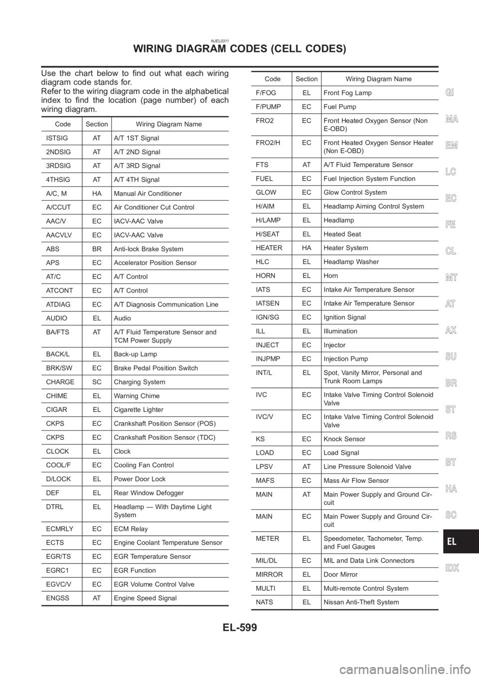
NJEL0311
Use the chart below to find out what each wiring
diagram code stands for.
Refer to the wiring diagram code in the alphabetical
index to find the location (page number) of each
wiring diagram.
Code Section Wiring Diagram Name
ISTSIG AT A/T 1ST Signal
2NDSIG AT A/T 2ND Signal
3RDSIG AT A/T 3RD Signal
4THSIG AT A/T 4TH Signal
A/C, M HA Manual Air Conditioner
A/CCUT EC Air Conditioner Cut Control
AAC/V EC IACV-AAC Valve
AACVLV EC IACV-AAC Valve
ABS BR Anti-lock Brake System
APS EC Accelerator Position Sensor
AT/C EC A/T Control
ATCONT EC A/T Control
ATDIAG EC A/T Diagnosis Communication Line
AUDIO EL Audio
BA/FTS AT A/T Fluid Temperature Sensor and
TCM Power Supply
BACK/L EL Back-up Lamp
BRK/SW EC Brake Pedal Position Switch
CHARGE SC Charging System
CHIME EL Warning Chime
CIGAR EL Cigarette Lighter
CKPS EC Crankshaft Position Sensor (POS)
CKPS EC Crankshaft Position Sensor (TDC)
CLOCK EL Clock
COOL/F EC Cooling Fan Control
D/LOCK EL Power Door Lock
DEF EL Rear Window Defogger
DTRL EL Headlamp — With Daytime Light
System
ECMRLY EC ECM Relay
ECTS EC Engine Coolant Temperature Sensor
EGR/TS EC EGR Temperature Sensor
EGRC1 EC EGR Function
EGVC/V EC EGR Volume Control Valve
ENGSS AT Engine Speed Signal
Code Section Wiring Diagram Name
F/FOG EL Front Fog Lamp
F/PUMP EC Fuel Pump
FRO2 EC Front Heated Oxygen Sensor (Non
E-OBD)
FRO2/H EC Front Heated Oxygen Sensor Heater
(Non E-OBD)
FTS AT A/T Fluid Temperature Sensor
FUEL EC Fuel Injection System Function
GLOW EC Glow Control System
H/AIM EL Headlamp Aiming Control System
H/LAMP EL Headlamp
H/SEAT EL Heated Seat
HEATER HA Heater System
HLC EL Headlamp Washer
HORN EL Horn
IATS EC Intake Air Temperature Sensor
IATSEN EC Intake Air Temperature Sensor
IGN/SG EC Ignition Signal
ILL EL Illumination
INJECT EC Injector
INJPMP EC Injection Pump
INT/L EL Spot, Vanity Mirror, Personal and
Trunk Room Lamps
IVC EC Intake Valve Timing Control Solenoid
Valve
IVC/V EC Intake Valve Timing Control Solenoid
Valve
KS EC Knock Sensor
LOAD EC Load Signal
LPSV AT Line Pressure Solenoid Valve
MAFS EC Mass Air Flow Sensor
MAIN AT Main Power Supply and Ground Cir-
cuit
MAIN EC Main Power Supply and Ground Cir-
cuit
METER EL Speedometer, Tachometer, Temp.
and Fuel Gauges
MIL/DL EC MIL and Data Link Connectors
MIRROR EL Door Mirror
MULTI EL Multi-remote Control System
NATS EL Nissan Anti-Theft System
GI
MA
EM
LC
EC
FE
CL
MT
AT
AX
SU
BR
ST
RS
BT
HA
SC
IDX
WIRING DIAGRAM CODES (CELL CODES)
EL-599
Page 2936 of 3189
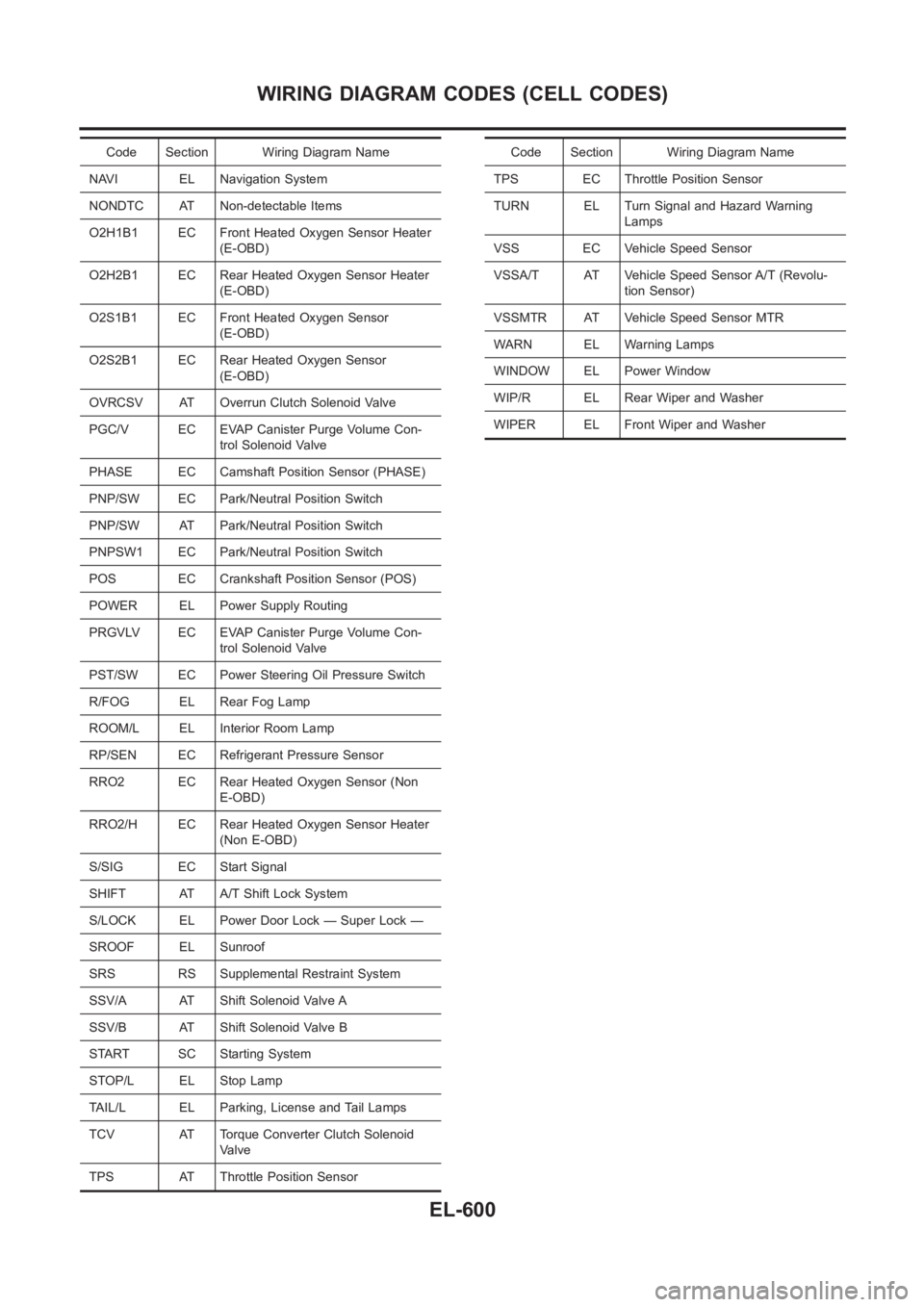
Code Section Wiring Diagram Name
NAVI EL Navigation System
NONDTC AT Non-detectable Items
O2H1B1 EC Front Heated Oxygen Sensor Heater
(E-OBD)
O2H2B1 EC Rear Heated Oxygen Sensor Heater
(E-OBD)
O2S1B1 EC Front Heated Oxygen Sensor
(E-OBD)
O2S2B1 EC Rear Heated Oxygen Sensor
(E-OBD)
OVRCSV AT Overrun Clutch Solenoid Valve
PGC/V EC EVAP Canister Purge Volume Con-
trol Solenoid Valve
PHASE EC Camshaft Position Sensor (PHASE)
PNP/SW EC Park/Neutral Position Switch
PNP/SW AT Park/Neutral Position Switch
PNPSW1 EC Park/Neutral Position Switch
POS EC Crankshaft Position Sensor (POS)
POWER EL Power Supply Routing
PRGVLV EC EVAP Canister Purge Volume Con-
trol Solenoid Valve
PST/SW EC Power Steering Oil Pressure Switch
R/FOG EL Rear Fog Lamp
ROOM/L EL Interior Room Lamp
RP/SEN EC Refrigerant Pressure Sensor
RRO2 EC Rear Heated Oxygen Sensor (Non
E-OBD)
RRO2/H EC Rear Heated Oxygen Sensor Heater
(Non E-OBD)
S/SIG EC Start Signal
SHIFT AT A/T Shift Lock System
S/LOCK EL Power Door Lock — Super Lock —
SROOF EL Sunroof
SRS RS Supplemental Restraint System
SSV/A AT Shift Solenoid Valve A
SSV/B AT Shift Solenoid Valve B
START SC Starting System
STOP/L EL Stop Lamp
TAIL/L EL Parking, License and Tail Lamps
TCV AT Torque Converter Clutch Solenoid
Valve
TPS AT Throttle Position SensorCode Section Wiring Diagram Name
TPS EC Throttle Position Sensor
TURN EL Turn Signal and Hazard Warning
Lamps
VSS EC Vehicle Speed Sensor
VSSA/T AT Vehicle Speed Sensor A/T (Revolu-
tion Sensor)
VSSMTR AT Vehicle Speed Sensor MTR
WARN EL Warning Lamps
WINDOW EL Power Window
WIP/R EL Rear Wiper and Washer
WIPER EL Front Wiper and Washer
WIRING DIAGRAM CODES (CELL CODES)
EL-600