2003 NISSAN ALMERA N16 fuse
[x] Cancel search: fusePage 193 of 3189

NJEM0053
JEM111G
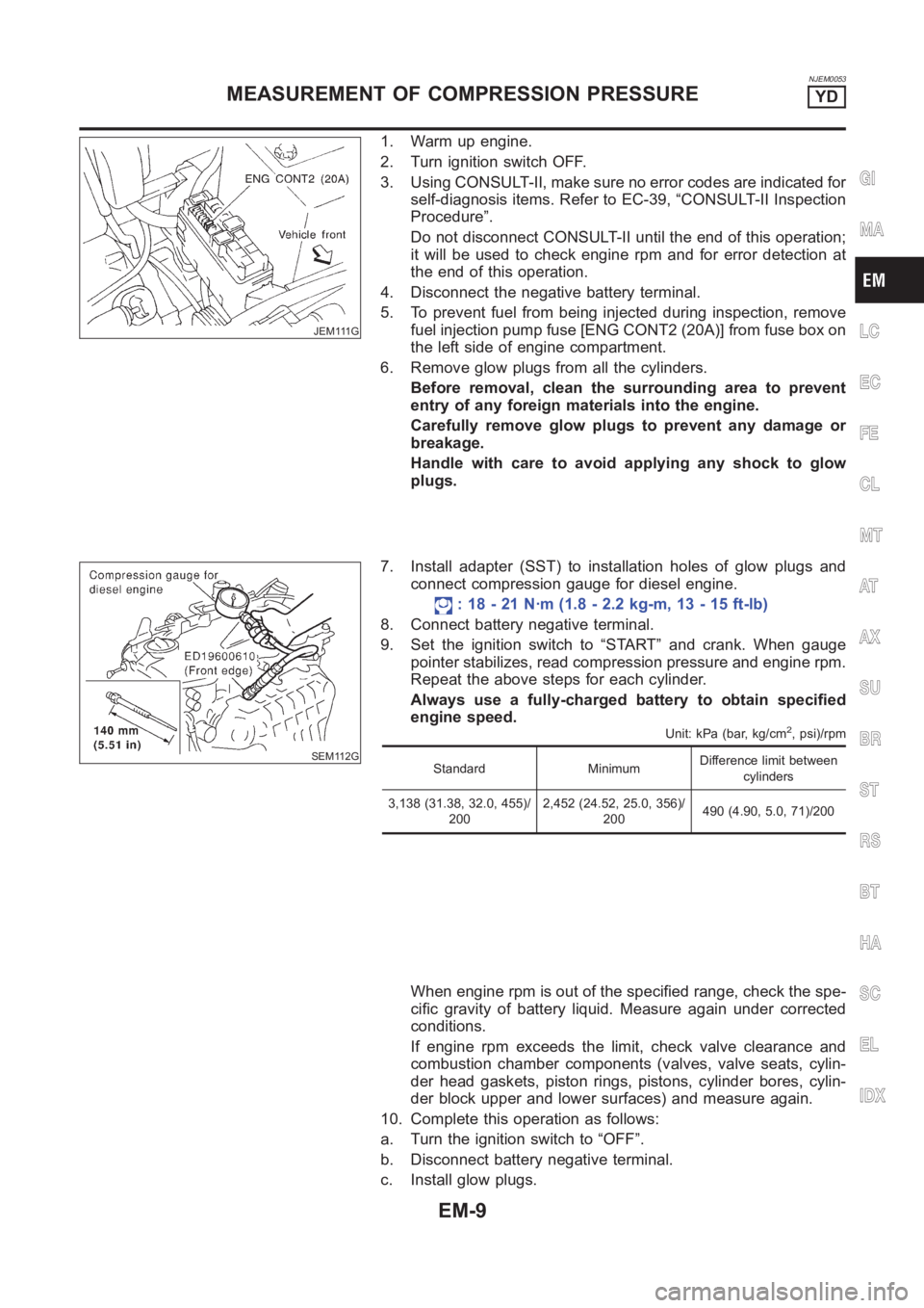
1. Warm up engine.
2. Turn ignition switch OFF.
3. Using CONSULT-II, make sure no error codes are indicated for
self-diagnosis items. Refer to EC-39, “CONSULT-II Inspection
Procedure”.
Do not disconnect CONSULT-II until the end of this operation;
it will be used to check engine rpm and for error detection at
the end of this operation.
4. Disconnect the negative battery terminal.
5. To prevent fuel from being injected during inspection, remove
fuel injection pump fuse [ENG CONT2 (20A)] from fuse box on
the left side of engine compartment.
6. Remove glow plugs from all the cylinders.
Before removal, clean the surrounding area to prevent
entry of any foreign materials into the engine.
Carefully remove glow plugs to prevent any damage or
breakage.
Handle with care to avoid applying any shock to glow
plugs.
SEM112G
7. Install adapter (SST) to installation holes of glow plugs and
connect compression gauge for diesel engine.
: 18 - 21 N·m (1.8 - 2.2 kg-m, 13 - 15 ft-lb)
8. Connect battery negative terminal.
9. Set the ignition switch to “START” and crank. When gauge
pointer stabilizes, read compression pressure and engine rpm.
Repeat the above steps for each cylinder.
Always use a fully-charged battery to obtain specified
engine speed.
Unit: kPa (bar, kg/cm2, psi)/rpm
Standard MinimumDifference limit between
cylinders
3,138 (31.38, 32.0, 455)/
2002,452 (24.52, 25.0, 356)/
200490 (4.90, 5.0, 71)/200
When engine rpm is out of the specified range, check the spe-
cific gravity of battery liquid. Measure again under corrected
conditions.
If engine rpm exceeds the limit, check valve clearance and
combustion chamber components (valves, valve seats, cylin-
der head gaskets, piston rings, pistons, cylinder bores, cylin-
der block upper and lower surfaces) and measure again.
10. Complete this operation as follows:
a. Turn the ignition switch to “OFF”.
b. Disconnect battery negative terminal.
c. Install glow plugs.
GI
MA
LC
EC
FE
CL
MT
AT
AX
SU
BR
ST
RS
BT
HA
SC
EL
IDX
MEASUREMENT OF COMPRESSION PRESSUREYD
EM-9
Page 194 of 3189
![NISSAN ALMERA N16 2003 Electronic Repair Manual d. Install fuel injection pump fuse [ENG CONT2 (20A)].
e. Connect battery negative terminal.
f. Using CONSULT-II make sure no error code is indicated for
items of self-diagnosis. Refer to EC-39, “CO NISSAN ALMERA N16 2003 Electronic Repair Manual d. Install fuel injection pump fuse [ENG CONT2 (20A)].
e. Connect battery negative terminal.
f. Using CONSULT-II make sure no error code is indicated for
items of self-diagnosis. Refer to EC-39, “CO](/manual-img/5/57350/w960_57350-193.png)
d. Install fuel injection pump fuse [ENG CONT2 (20A)].
e. Connect battery negative terminal.
f. Using CONSULT-II make sure no error code is indicated for
items of self-diagnosis. Refer to EC-39, “CONSULT-II Inspec-
tion Procedure”.
MEASUREMENT OF COMPRESSION PRESSUREYD
EM-10
Page 201 of 3189

JEM116G
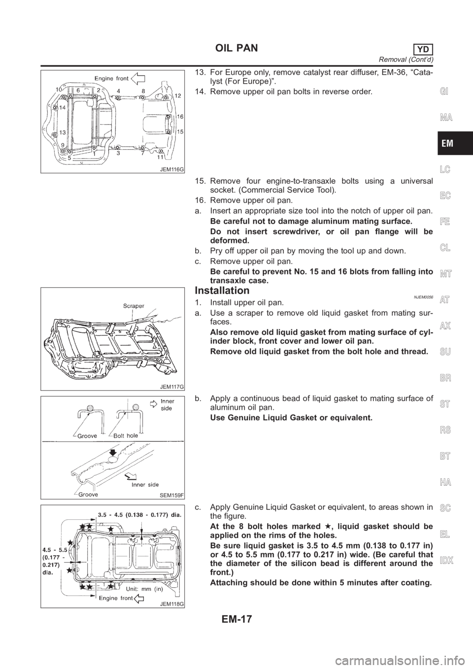
13. For Europe only, remove catalyst rear diffuser, EM-36, “Cata-
lyst (For Europe)”.
14. Remove upper oil pan bolts in reverse order.
15. Remove four engine-to-transaxle bolts using a universal
socket. (Commercial Service Tool).
16. Remove upper oil pan.
a. Insert an appropriate size tool into the notch of upper oil pan.
Be careful not to damage aluminum mating surface.
Do not insert screwdriver, or oil pan flange will be
deformed.
b. Pry off upper oil pan by moving the tool up and down.
c. Remove upper oil pan.
Be careful to prevent No. 15 and 16 blots from falling into
transaxle case.
JEM117G
InstallationNJEM00561. Install upper oil pan.
a. Use a scraper to remove old liquid gasket from mating sur-
faces.
Also remove old liquid gasket from mating surface of cyl-
inder block, front cover and lower oil pan.
Remove old liquid gasket from the bolt hole and thread.
SEM159F
b. Apply a continuous bead of liquid gasket to mating surface of
aluminum oil pan.
Use Genuine Liquid Gasket or equivalent.
JEM118G
c. Apply Genuine Liquid Gasket or equivalent, to areas shown in
the figure.
At the 8 bolt holes marked★, liquid gasket should be
applied on the rims of the holes.
Be sure liquid gasket is 3.5 to 4.5 mm (0.138 to 0.177 in)
or 4.5 to 5.5 mm (0.177 to 0.217 in) wide. (Be careful that
the diameter of the silicon bead is different around the
front.)
Attaching should be done within 5 minutes after coating.
GI
MA
LC
EC
FE
CL
MT
AT
AX
SU
BR
ST
RS
BT
HA
SC
EL
IDX
OIL PANYD
Removal (Cont’d)
EM-17
Page 220 of 3189

Removal and InstallationNJEM0101
JEM264G
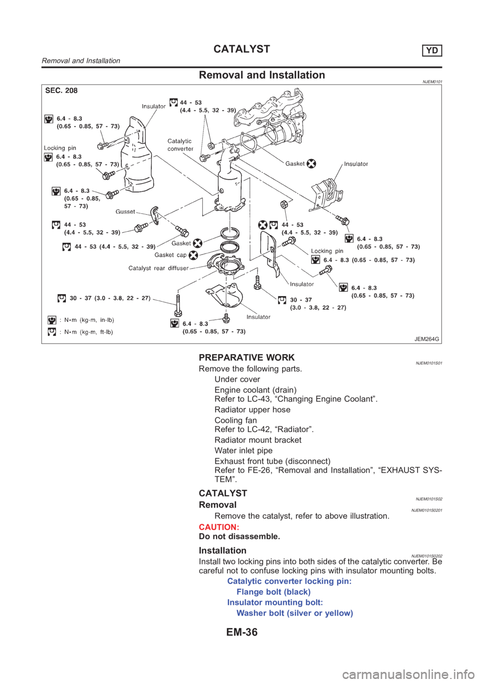
PREPARATIVE WORKNJEM0101S01Remove the following parts.
Under cover
Engine coolant (drain)
Refer to LC-43, “Changing Engine Coolant”.
Radiator upper hose
Cooling fan
Refer to LC-42, “Radiator”.
Radiator mount bracket
Water inlet pipe
Exhaust front tube (disconnect)
Refer to FE-26, “Removal and Installation”, “EXHAUST SYS-
TEM”.
CATALYSTNJEM0101S02RemovalNJEM0101S0201Remove the catalyst, refer to above illustration.
CAUTION:
Do not disassemble.
InstallationNJEM0101S0202Install two locking pins into both sides of the catalytic converter. Be
careful not to confuse locking pins with insulator mounting bolts.
Catalytic converter locking pin:
Flange bolt (black)
Insulator mounting bolt:
Washer bolt (silver or yellow)
CATALYSTYD
Removal and Installation
EM-36
Page 364 of 3189
![NISSAN ALMERA N16 2003 Electronic Repair Manual EC-34
[QG (WITH EURO-OBD)]
BASIC SERVICE PROCEDURE
DIAGNOSTIC PROCEDURE
If idle air volume learning cannot be performed successfully, proceed as follows:
1.Check that throttle valve is fully closed.
2 NISSAN ALMERA N16 2003 Electronic Repair Manual EC-34
[QG (WITH EURO-OBD)]
BASIC SERVICE PROCEDURE
DIAGNOSTIC PROCEDURE
If idle air volume learning cannot be performed successfully, proceed as follows:
1.Check that throttle valve is fully closed.
2](/manual-img/5/57350/w960_57350-363.png)
EC-34
[QG (WITH EURO-OBD)]
BASIC SERVICE PROCEDURE
DIAGNOSTIC PROCEDURE
If idle air volume learning cannot be performed successfully, proceed as follows:
1.Check that throttle valve is fully closed.
2.Check PCV valve operation.
3.Check that downstream of throttle valve is free from air leakage.
4.When the above three items check out OK, engine component parts and their installation condi-
tion are questionable. Check and eliminate the cause of the incident.
It is useful to perform EC-105, "
TROUBLE DIAGNOSIS - SPECIFICATION VALUE" .
5.If any of the following conditions occur after the engine has started, eliminate the cause of the
incident and perform “Idle air volume learning” all over again:
–Engine stalls.
–Erroneous idle.
Fuel Pressure CheckEBS00K3E
FUEL PRESSURE RELEASE
Before disconnecting fuel line, release fuel pressure from fuel line to eliminate danger.
NOTE:
Prepare pans or saucers under the disconnected fuel line because the fuel may spill out. The fuel pres-
sure cannot be completely released because N16 models do not have fuel return system.
With CONSULT-II
1. Turn ignition switch “ON”.
2. Perform “FUEL PRESSURE RELEASE” in “WORK SUPPORT”
mode with CONSULT-II.
3. Start engine.
4. After engine stalls, crank it two or three times to release all fuel
pressure.
5. Turn ignition switch “OFF”.
Without CONSULT-II
1. Remove fuel pump fuse located in fuse box.
2. Start engine.
3. After engine stalls, crank it two or three times to release all fuel
pressure.
4. Turn ignition switch “OFF”.
5. Reinstall fuel pump fuse after servicing fuel system.
FUEL PRESSURE CHECK
NOTE:
●When reconnecting fuel line, always use new clamps.
●Make sure that clamp screw does not contact adjacent parts.
●Use a torque driver to tighten clamps.
●Use Pressure Gauge to check fuel pressure.
1. Release fuel pressure to zero. Refer to EC-34, "
FUEL PRESSURE RELEASE" .
SEF214Y
MBIB0262E
Page 428 of 3189
![NISSAN ALMERA N16 2003 Electronic Repair Manual EC-98
[QG (WITH EURO-OBD)]
TROUBLE DIAGNOSIS
FUNCTION
GST INSPECTION PROCEDURE
1. Turn ignition switch OFF.
2. Connect “GST” to data link connector, which is located under the
driver side dash pan NISSAN ALMERA N16 2003 Electronic Repair Manual EC-98
[QG (WITH EURO-OBD)]
TROUBLE DIAGNOSIS
FUNCTION
GST INSPECTION PROCEDURE
1. Turn ignition switch OFF.
2. Connect “GST” to data link connector, which is located under the
driver side dash pan](/manual-img/5/57350/w960_57350-427.png)
EC-98
[QG (WITH EURO-OBD)]
TROUBLE DIAGNOSIS
FUNCTION
GST INSPECTION PROCEDURE
1. Turn ignition switch OFF.
2. Connect “GST” to data link connector, which is located under the
driver side dash panel near the fuse box cover.
3. Turn ignition switch ON.
4. Enter the program according to instruction on the screen or in
the operation manual.
(*: Regarding GST screens in this section, sample screens are
shown.)
Diagnostic test mode Function
MODE 1 READINESS TESTSThis mode gains access to current emission-related data values, including analog inputs
and outputs, digital inputs and outputs, and system status information.
MODE 2 (FREEZE DATA)This mode gains access to emission-related data value which were stored by ECM during
the freeze frame. For details, refer to EC-40, "
FREEZE FRAME DATA AND 1ST TRIP
FREEZE FRAME DATA" .
MODE 3 DTCsThis mode gains access to emission-related power train trouble codes which were stored
by ECM.
MODE 4 CLEAR DIAG INFOThis mode can clear all emission-related diagnostic information. This includes:
●Clear number of diagnostic trouble codes (MODE 1)
●Clear diagnostic trouble codes (MODE 3)
●Clear trouble code for freeze frame data (MODE 1)
●Clear freeze frame data (MODE 2)
●Reset status of system monitoring test (MODE 1)
●Clear on board monitoring test results (MODE 6 and 7)
MODE 6 (ON BOARD TESTS)This mode accesses the results of on board diagnostic monitoring tests of specific com-
ponents/systems that are not continuously monitored.
MODE 7 (ON BOARD TESTS)This mode enables the off board test drive to obtain test results for emission-related pow-
ertrain components/systems that are continuously monitored during normal driving condi-
tions.
MODE 8 — This mode is not applicable on this vehicle.
MODE 9 (CALIBRATION ID)This mode enables the off-board test device to request specific vehicle information such
as Vehicle Identification Number (VIN) and Calibration IDs.
MBIB0251E
SEF398S
Page 442 of 3189
![NISSAN ALMERA N16 2003 Electronic Repair Manual EC-112
[QG (WITH EURO-OBD)]
POWER SUPPLY CIRCUIT FOR ECM
3. DETECT MALFUNCTIONING PART
Check the following.
●Harness connectors M202, F115
●Fuse block (J/B) connector M1
●10A fuse
●Harness for NISSAN ALMERA N16 2003 Electronic Repair Manual EC-112
[QG (WITH EURO-OBD)]
POWER SUPPLY CIRCUIT FOR ECM
3. DETECT MALFUNCTIONING PART
Check the following.
●Harness connectors M202, F115
●Fuse block (J/B) connector M1
●10A fuse
●Harness for](/manual-img/5/57350/w960_57350-441.png)
EC-112
[QG (WITH EURO-OBD)]
POWER SUPPLY CIRCUIT FOR ECM
3. DETECT MALFUNCTIONING PART
Check the following.
●Harness connectors M202, F115
●Fuse block (J/B) connector M1
●10A fuse
●Harness for open or short between ECM and fuse
>> Repair open circuit or short to ground or short to power in harness or connectors.
4. CHECK ECM GROUND CIRCUIT FOR OPEN AND SHORT-I
1. Turn ignition switch “OFF”.
2. Disconnect ECM harness connector.
3. Check harness continuity between ECM terminals 1, 115, 116 and engine ground.
Refer to Wiring Diagram.
4. Also check harness for short to power.
OK or NG
OK >> GO TO 5.
NG >> Repair open circuit or short to power in harness or connectors.
5. CHECK ECM POWER SUPPLY CIRCUIT-II
1. Disconnect ECM relay.
2. Check voltage between ECM relay terminals 1 and 6 and
ground with CONSULT-II or tester.
OK or NG
OK >> GO TO 7.
NG >> GO TO 6.Continuity should exist.
MBIB0247E
Voltage: Battery voltage
SEF420X
Page 443 of 3189
![NISSAN ALMERA N16 2003 Electronic Repair Manual POWER SUPPLY CIRCUIT FOR ECM
EC-113
[QG (WITH EURO-OBD)]
C
D
E
F
G
H
I
J
K
L
MA
EC
6.DETECT MALFUNCTIONING PART
Check the following.
●10A fuse
●15A fuse
●Harness for open or short between ECM re NISSAN ALMERA N16 2003 Electronic Repair Manual POWER SUPPLY CIRCUIT FOR ECM
EC-113
[QG (WITH EURO-OBD)]
C
D
E
F
G
H
I
J
K
L
MA
EC
6.DETECT MALFUNCTIONING PART
Check the following.
●10A fuse
●15A fuse
●Harness for open or short between ECM re](/manual-img/5/57350/w960_57350-442.png)
POWER SUPPLY CIRCUIT FOR ECM
EC-113
[QG (WITH EURO-OBD)]
C
D
E
F
G
H
I
J
K
L
MA
EC
6.DETECT MALFUNCTIONING PART
Check the following.
●10A fuse
●15A fuse
●Harness for open or short between ECM relay and battery
>> Repair open circuit or short to ground or short to power in harness or connectors.
7.CHECK OUTPUT SIGNAL CIRCUIT FOR OPEN AND SHORT
1. Check harness continuity between ECM terminal 111 and ECM relay terminal 2.
Refer to Wiring Diagram.
2. Also check harness for short to ground and short to power.
OK or NG
OK >> GO TO 9.
NG >> GO TO 8.
8.DETECT MALFUNCTIONING PART
Check the following.
●Harness connectors E225, F43
●Harness for open or short between ECM and ECM relay
>> Repair open circuit or short to ground or short to power in harness or connectors.
9.CHECK ECM RELAY
Refer to EC-115, "
Component Inspection" .
OK or NG
OK >> GO TO EC-365, "IGNITION SIGNAL" .
NG >> Replace ECM relay.
10.CHECK ECM POWER SUPPLY CIRCUIT-III
1. Stop engine and wait at least 10 seconds.
2. Turn ignition switch “ON” and then “OFF”.
3. Check voltage between ECM terminals 119, 120 and ground
with CONSULT-II or tester.
OK or NG
OK >> GO TO 14.
NG (Battery voltage does not exist.)>>GO TO 11.
NG (Battery voltage exists for more than a few seconds.)>>GO TO 12. Continuity should exist.
Voltage: After turning ignition switch “OFF”, battery
voltage will exist for a few seconds, then
drop approximately 0V.
MBIB0016E