Page 1129 of 3189
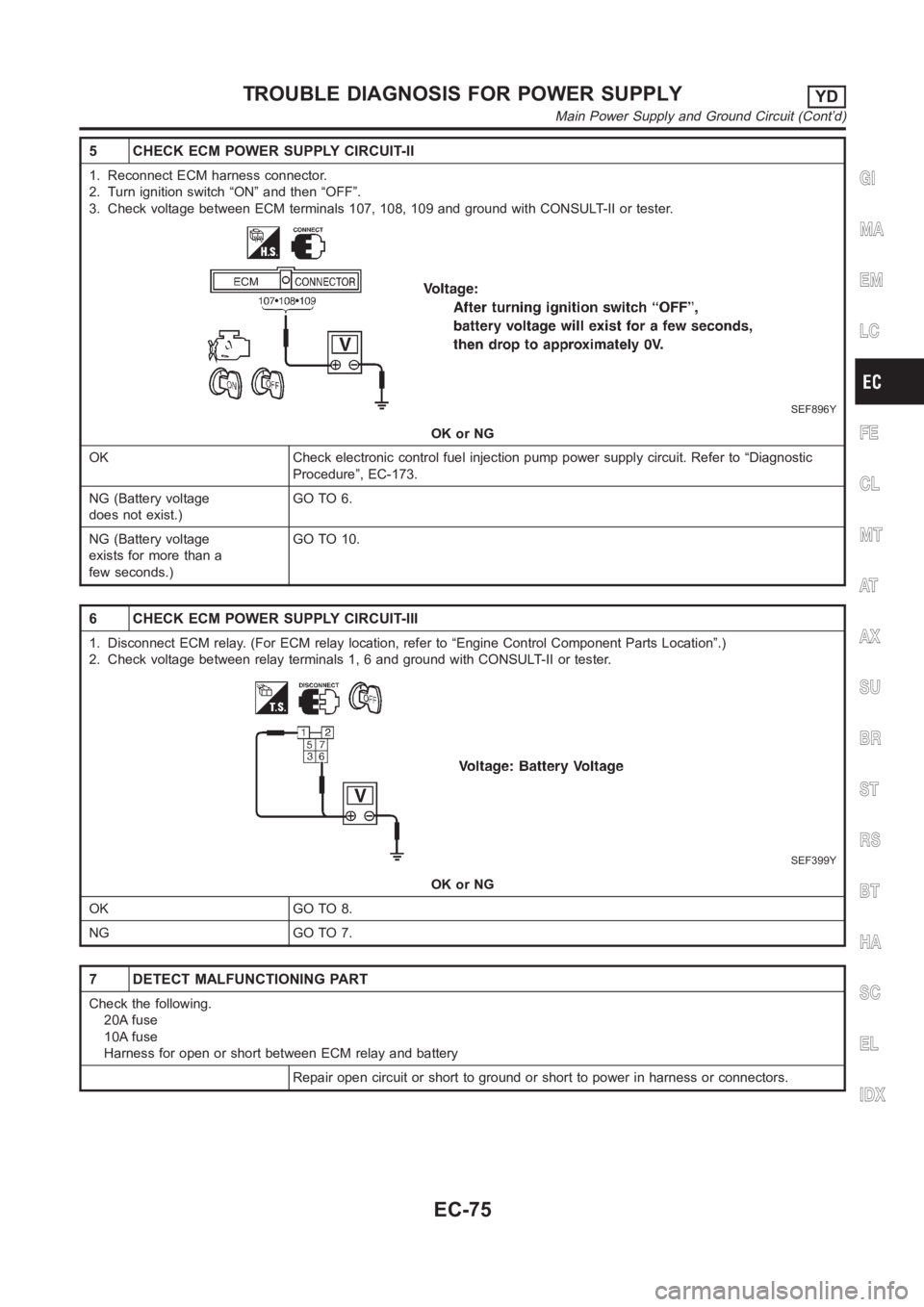
5 CHECK ECM POWER SUPPLY CIRCUIT-II
1. Reconnect ECM harness connector.
2. Turn ignition switch “ON” and then “OFF”.
3. Check voltage between ECM terminals 107, 108, 109 and ground with CONSULT-II or tester.
SEF896Y
OK or NG
OK Check electronic control fuel injection pump power supply circuit. Refer to “Diagnostic
Procedure”, EC-173.
NG (Battery voltage
does not exist.)GO TO 6.
NG (Battery voltage
exists for more than a
few seconds.)GO TO 10.
6 CHECK ECM POWER SUPPLY CIRCUIT-III
1. Disconnect ECM relay. (For ECM relay location, refer to “Engine ControlComponent Parts Location”.)
2. Check voltage between relay terminals 1, 6 and ground with CONSULT-II ortester.
SEF399Y
OK or NG
OK GO TO 8.
NG GO TO 7.
7 DETECT MALFUNCTIONING PART
Check the following.
20A fuse
10A fuse
Harness for open or short between ECM relay and battery
Repair open circuit or short to ground or short to power in harness or connectors.
GI
MA
EM
LC
FE
CL
MT
AT
AX
SU
BR
ST
RS
BT
HA
SC
EL
IDX
TROUBLE DIAGNOSIS FOR POWER SUPPLYYD
Main Power Supply and Ground Circuit (Cont’d)
EC-75
Page 1166 of 3189
Diagnostic ProcedureNJEC0743
1 CHECK STOP LAMP SWITCH CIRCUIT
1. Turn ignition switch “OFF”.
2. Check the stop lamp when depressing and releasing the stop lamp switch.
MTBL0443
OK or NG
OK GO TO 4.
NG GO TO 2.
2 CHECK STOP LAMP SWITCH POWER SUPPLY CIRCUIT
1. Disconnect stop lamp switch harness connector.
SEF893Y
2. Check voltage between stop lamp switch terminal 1 and ground with CONSULT-II or tester.
SEF435Y
OK or NG
OK GO TO 4.
NG GO TO 3.
3 DETECT MALFUNCTIONING PART
Check the following.
Fuse block (J/B) connector M2
10A fuse
Harness for open and short between stop lamp switch and fuse
Repair open circuit or short to ground or short to power in harness or connectors.
DTC P0571 BRAKE SWYD
Diagnostic Procedure
EC-112
Page 1193 of 3189
2 DETECT MALFUNCTIONING PART
Check the following.
Fuse block (J/B) connector E104
10A fuse
40A fusible link
Harness for open or short between cooling fan relay-1 and fuse
Harness for open or short between cooling fan relay-1 and battery
Repair open circuit or short to ground or short to power in harness or connectors.
3 CHECK COOLING FAN GROUND CIRCUIT FOR OPEN AND SHORT-I
1. Turn ignition switch “OFF”.
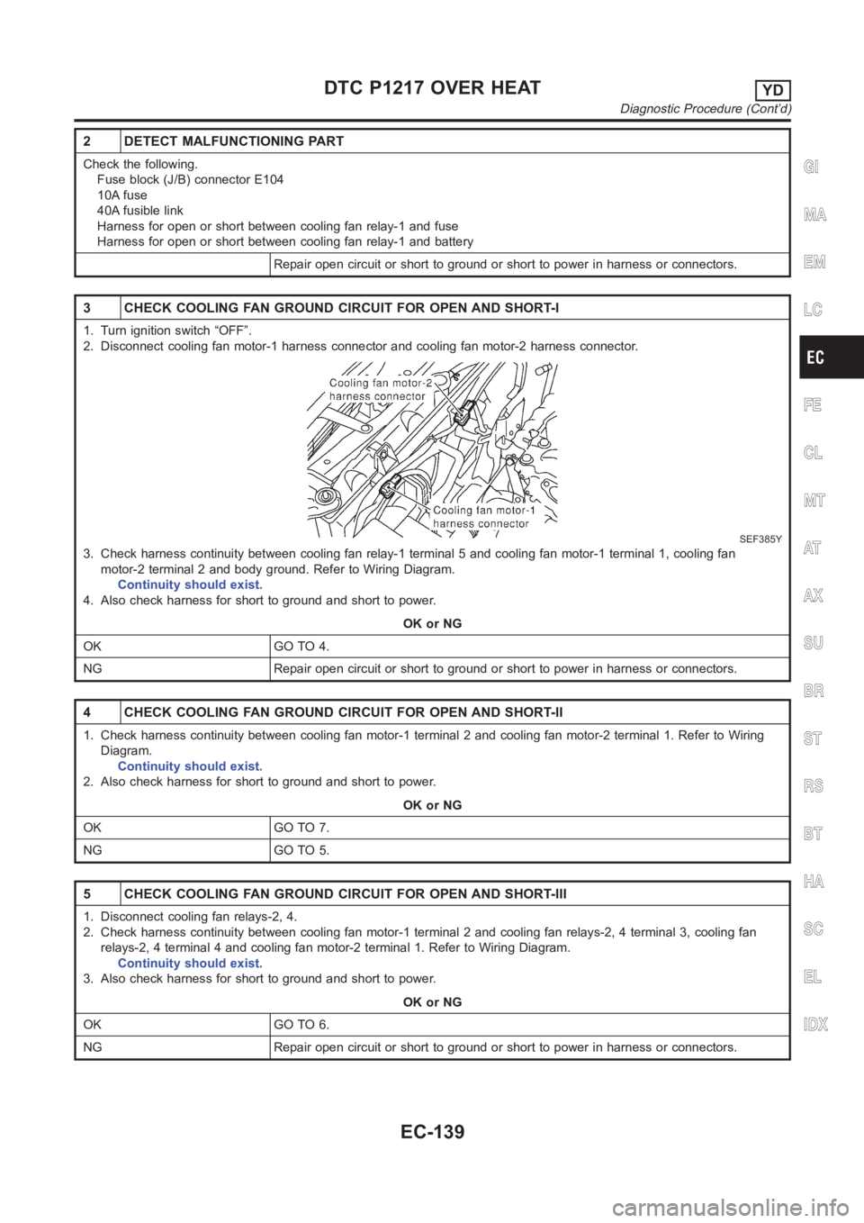
2. Disconnect cooling fan motor-1 harness connector and cooling fan motor-2 harness connector.
SEF385Y
3. Check harness continuity between cooling fan relay-1 terminal 5 and cooling fan motor-1 terminal 1, cooling fan
motor-2 terminal 2 and body ground. Refer to Wiring Diagram.
Continuity should exist.
4. Also check harness for short to ground and short to power.
OK or NG
OK GO TO 4.
NG Repair open circuit or short to ground or short to power in harness or connectors.
4 CHECK COOLING FAN GROUND CIRCUIT FOR OPEN AND SHORT-II
1. Check harness continuity between cooling fan motor-1 terminal 2 and cooling fan motor-2 terminal 1. Refer to Wiring
Diagram.
Continuity should exist.
2. Also check harness for short to ground and short to power.
OK or NG
OK GO TO 7.
NG GO TO 5.
5 CHECK COOLING FAN GROUND CIRCUIT FOR OPEN AND SHORT-III
1. Disconnect cooling fan relays-2, 4.
2. Check harness continuity between cooling fan motor-1 terminal 2 and cooling fan relays-2, 4 terminal 3, cooling fan
relays-2, 4 terminal 4 and cooling fan motor-2 terminal 1. Refer to Wiring Diagram.
Continuity should exist.
3. Also check harness for short to ground and short to power.
OK or NG
OK GO TO 6.
NG Repair open circuit or short to ground or short to power in harness or connectors.
GI
MA
EM
LC
FE
CL
MT
AT
AX
SU
BR
ST
RS
BT
HA
SC
EL
IDX
DTC P1217 OVER HEATYD
Diagnostic Procedure (Cont’d)
EC-139
Page 1196 of 3189
2 DETECT MALFUNCTIONING PART
Check the following.
30A fusible link
10A fuse
Harness for open or short between cooling fan relays-2, 3, 4 and fuse
Harness for open or short between cooling fan relay-3 and fusible link
Repair harness or connectors.
3 CHECK COOLING FAN GROUND CIRCUIT FOR OPEN AND SHORT
1. Turn ignition switch “OFF”.
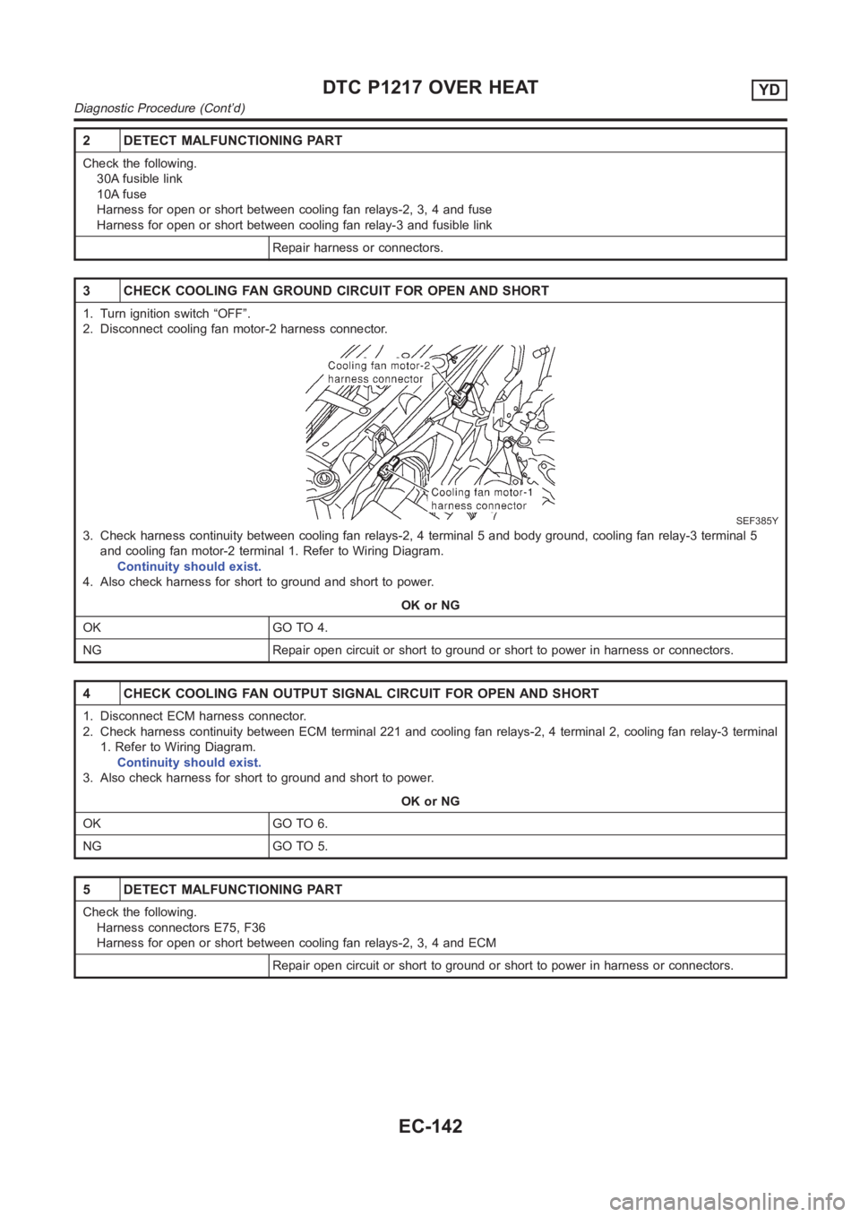
2. Disconnect cooling fan motor-2 harness connector.
SEF385Y
3. Check harness continuity between cooling fan relays-2, 4 terminal 5 andbody ground, cooling fan relay-3 terminal 5
and cooling fan motor-2 terminal 1. Refer to Wiring Diagram.
Continuity should exist.
4. Also check harness for short to ground and short to power.
OK or NG
OK GO TO 4.
NG Repair open circuit or short to ground or short to power in harness or connectors.
4 CHECK COOLING FAN OUTPUT SIGNAL CIRCUIT FOR OPEN AND SHORT
1. Disconnect ECM harness connector.
2. Check harness continuity between ECM terminal 221 and cooling fan relays-2, 4 terminal 2, cooling fan relay-3 terminal
1. Refer to Wiring Diagram.
Continuity should exist.
3. Also check harness for short to ground and short to power.
OK or NG
OK GO TO 6.
NG GO TO 5.
5 DETECT MALFUNCTIONING PART
Check the following.
Harness connectors E75, F36
Harness for open or short between cooling fan relays-2, 3, 4 and ECM
Repair open circuit or short to ground or short to power in harness or connectors.
DTC P1217 OVER HEATYD
Diagnostic Procedure (Cont’d)
EC-142
Page 1233 of 3189
Diagnostic ProcedureNJEC0748
1 CHECK ECM POWER SUPPLY CIRCUIT
1. Turn ignition switch “OFF”.
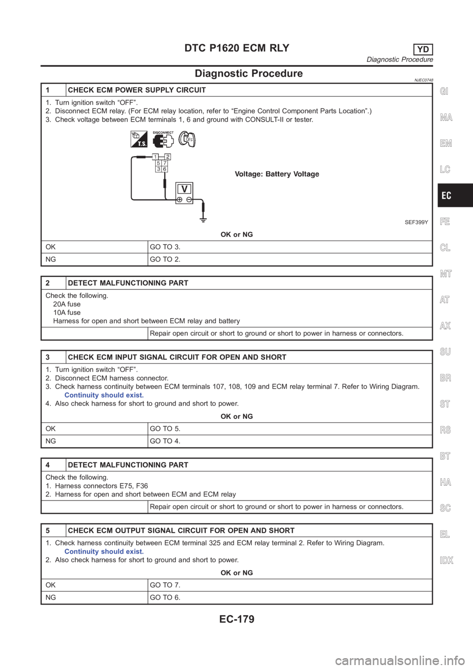
2. Disconnect ECM relay. (For ECM relay location, refer to “Engine ControlComponent Parts Location”.)
3. Check voltage between ECM terminals 1, 6 and ground with CONSULT-II or tester.
SEF399Y
OK or NG
OK GO TO 3.
NG GO TO 2.
2 DETECT MALFUNCTIONING PART
Check the following.
20A fuse
10A fuse
Harness for open and short between ECM relay and battery
Repair open circuit or short to ground or short to power in harness or connectors.
3 CHECK ECM INPUT SIGNAL CIRCUIT FOR OPEN AND SHORT
1. Turn ignition switch “OFF”.
2. Disconnect ECM harness connector.
3. Check harness continuity between ECM terminals 107, 108, 109 and ECM relay terminal 7. Refer to Wiring Diagram.
Continuity should exist.
4. Also check harness for short to ground and short to power.
OK or NG
OK GO TO 5.
NG GO TO 4.
4 DETECT MALFUNCTIONING PART
Check the following.
1. Harness connectors E75, F36
2. Harness for open and short between ECM and ECM relay
Repair open circuit or short to ground or short to power in harness or connectors.
5 CHECK ECM OUTPUT SIGNAL CIRCUIT FOR OPEN AND SHORT
1. Check harness continuity between ECM terminal 325 and ECM relay terminal 2. Refer to Wiring Diagram.
Continuity should exist.
2. Also check harness for short to ground and short to power.
OK or NG
OK GO TO 7.
NG GO TO 6.
GI
MA
EM
LC
FE
CL
MT
AT
AX
SU
BR
ST
RS
BT
HA
SC
EL
IDX
DTC P1620 ECM RLYYD
Diagnostic Procedure
EC-179
Page 1238 of 3189
2 CHECK BATTERY AND ALTERNATOR
Check that the proper type of battery and alternator is installed.
Refer to SC-37, “Battery” and SC-38, “Alternator”.
OK or NG
OK GO TO 5.
NG Replace with a proper one.
3 CHECK JUMPER CABLES INSTALLATION
Check that the jumper cables are connected in the correct sequence.
SEF439Z
OK or NG
OK GO TO 4.
NG Reconnect jumper cables properly.
4 CHECK BATTERY FOR BOOSTER
Check that the battery for the booster is a 12V battery.
OK or NG
OK GO TO 5.
NG Change the vehicle for booster.
5 PERFORM DTC CONFIRMATION PROCEDURE AGAIN
Perform “DTC Confirmation Procedure”, EC-183, again.
OK or NG
OK GO TO 6.
NG Replace ECM.
6 CHECK ELECTRICAL PARTS DAMAGE
Check the following for damage.
Wiring harness and harness connectors for burn
Fuses for short
OK or NG
OKINSPECTION END
NG Repair or replace malfunctioning part.
DTC P1660 BATTERY VOLTAGEYD
Diagnostic Procedure (Cont’d)
EC-184
Page 1247 of 3189
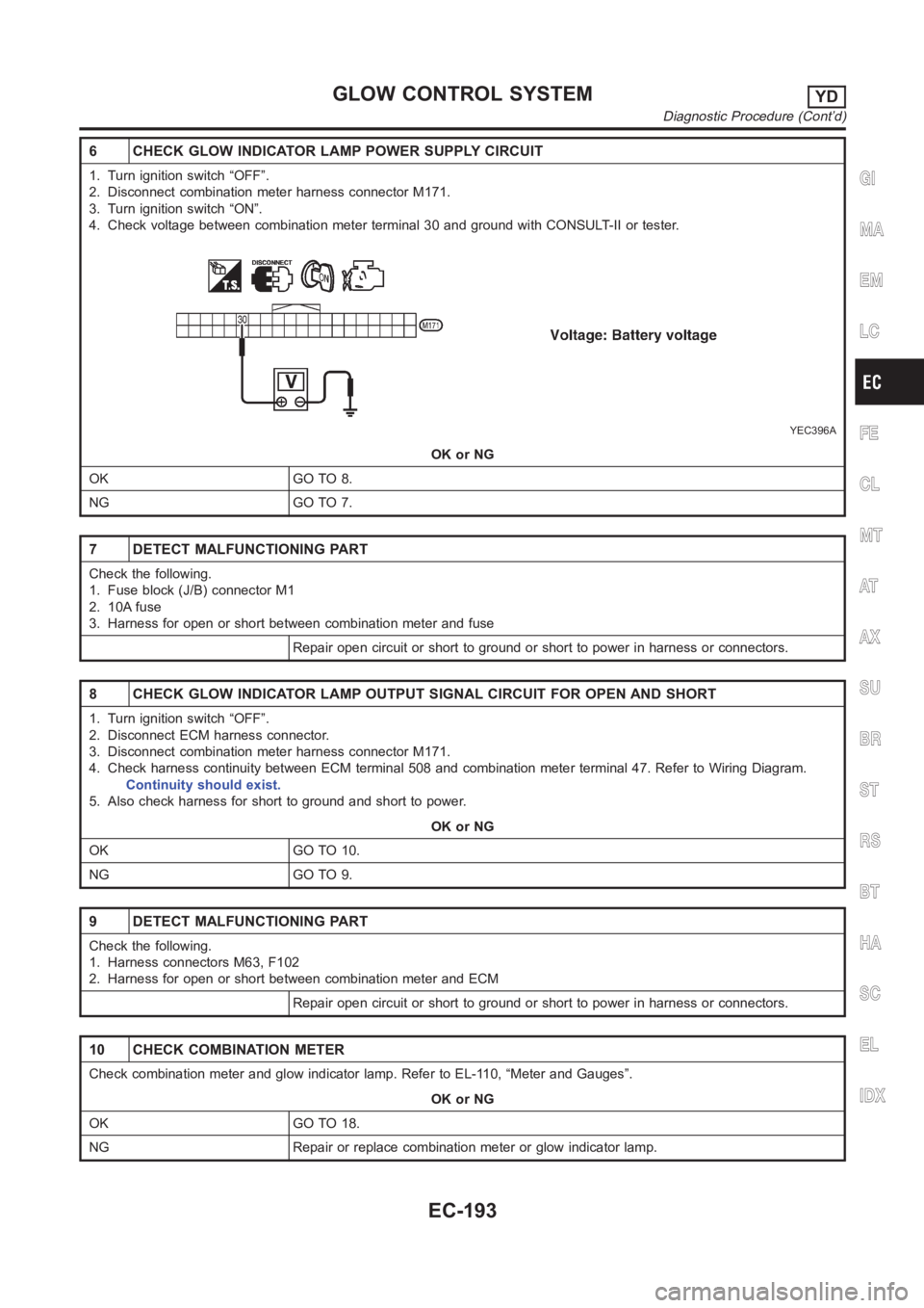
6 CHECK GLOW INDICATOR LAMP POWER SUPPLY CIRCUIT
1. Turn ignition switch “OFF”.
2. Disconnect combination meter harness connector M171.
3. Turn ignition switch “ON”.
4. Check voltage between combination meter terminal 30 and ground with CONSULT-II or tester.
YEC396A
OK or NG
OK GO TO 8.
NG GO TO 7.
7 DETECT MALFUNCTIONING PART
Check the following.
1. Fuse block (J/B) connector M1
2. 10A fuse
3. Harness for open or short between combination meter and fuse
Repair open circuit or short to ground or short to power in harness or connectors.
8 CHECK GLOW INDICATOR LAMP OUTPUT SIGNAL CIRCUIT FOR OPEN AND SHORT
1. Turn ignition switch “OFF”.
2. Disconnect ECM harness connector.
3. Disconnect combination meter harness connector M171.
4. Check harness continuity between ECM terminal 508 and combination meter terminal 47. Refer to Wiring Diagram.
Continuity should exist.
5. Also check harness for short to ground and short to power.
OK or NG
OK GO TO 10.
NG GO TO 9.
9 DETECT MALFUNCTIONING PART
Check the following.
1. Harness connectors M63, F102
2. Harness for open or short between combination meter and ECM
Repair open circuit or short to ground or short to power in harness or connectors.
10 CHECK COMBINATION METER
Check combination meter and glow indicator lamp. Refer to EL-110, “Meter and Gauges”.
OK or NG
OK GO TO 18.
NG Repair or replace combination meter or glow indicator lamp.
GI
MA
EM
LC
FE
CL
MT
AT
AX
SU
BR
ST
RS
BT
HA
SC
EL
IDX
GLOW CONTROL SYSTEMYD
Diagnostic Procedure (Cont’d)
EC-193
Page 1255 of 3189
3 CHECK EGR VOLUME CONTROL VALVE POWER SUPPLY CIRCUIT-II
1. Turn ignition switch “OFF”.
2. Disconnect ECM relay. (For ECM relay location, refer to “Engine ControlComponent Parts Location”.)
3. Check harness continuity between ECM relay terminal 5 and EGR volume control valve terminals 2 and 5. Refer to
Wiring Diagram.
Continuity should exist.
OK or NG
OK GO TO 5.
NG GO TO 4.
4 DETECT MALFUNCTIONING PART
Check the following.
Harness connectors E174, M159 (LHD models)
Harness connectors E251, M182 (RHD models)
Harness connectors M63, F102
Harness for open or short between ECM relay and EGR volume control valve
Repair open circuit or short to power in harness or connectors.
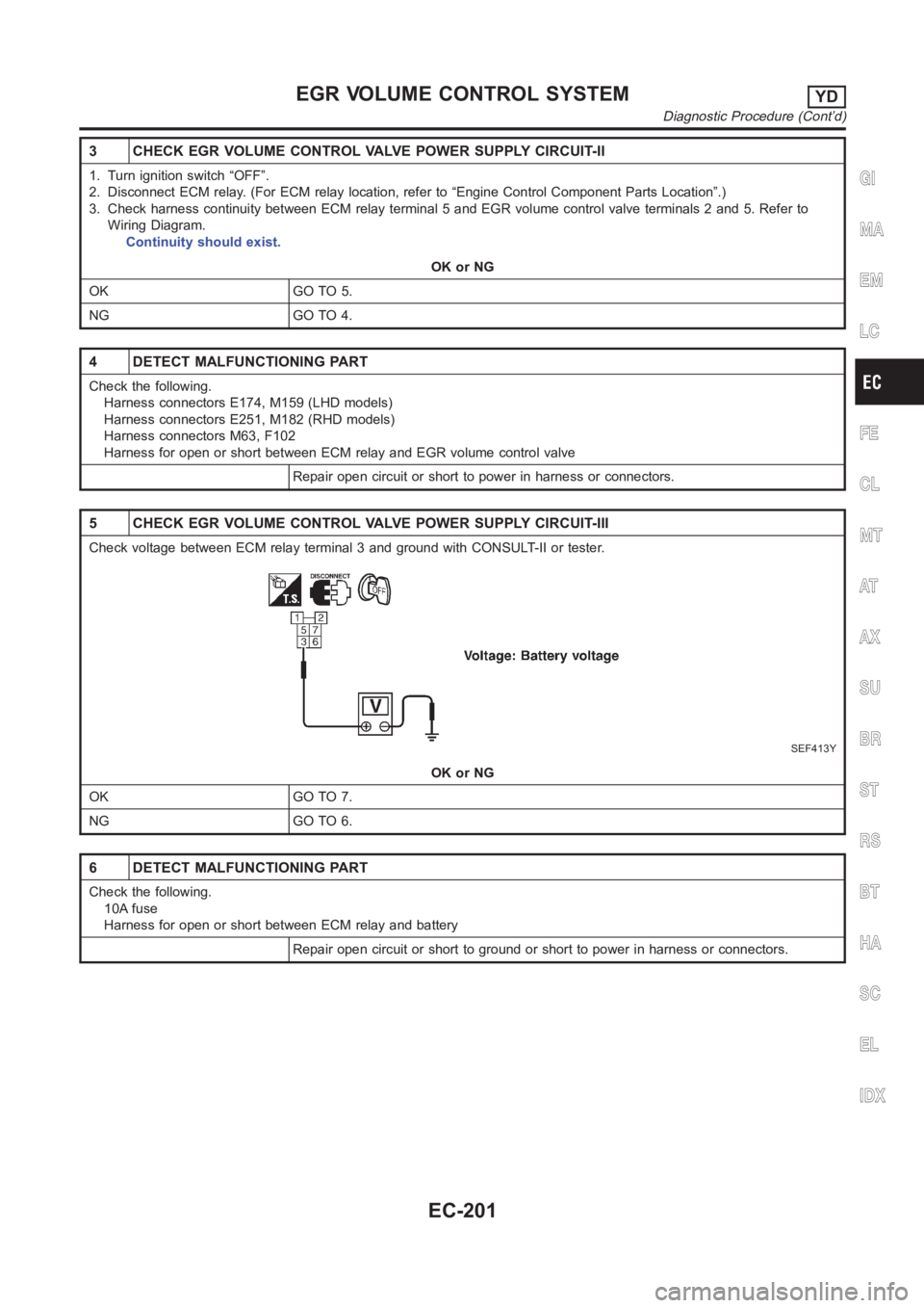
5 CHECK EGR VOLUME CONTROL VALVE POWER SUPPLY CIRCUIT-III
Check voltage between ECM relay terminal 3 and ground with CONSULT-II or tester.
SEF413Y
OK or NG
OK GO TO 7.
NG GO TO 6.
6 DETECT MALFUNCTIONING PART
Check the following.
10A fuse
Harness for open or short between ECM relay and battery
Repair open circuit or short to ground or short to power in harness or connectors.
GI
MA
EM
LC
FE
CL
MT
AT
AX
SU
BR
ST
RS
BT
HA
SC
EL
IDX
EGR VOLUME CONTROL SYSTEMYD
Diagnostic Procedure (Cont’d)
EC-201