Page 2170 of 3189
SFA449BB
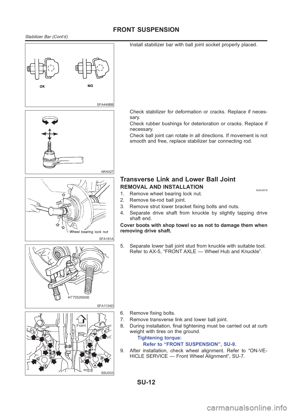
Install stabilizer bar with ball joint socket properly placed.
ARA027
Check stabilizer for deformation or cracks. Replace if neces-
sary.
Check rubber bushings for deterioration or cracks. Replace if
necessary.
Check ball joint can rotate in all directions. If movement is not
smooth and free, replace stabilizer bar connecting rod.
SFA181A
Transverse Link and Lower Ball Joint
REMOVAL AND INSTALLATIONNJSU00181. Remove wheel bearing lock nut.
2. Remove tie-rod ball joint.
3. Remove strut lower bracket fixing bolts and nuts.
4. Separate drive shaft from knuckle by slightly tapping drive
shaft end.
Cover boots with shop towel so as not to damage them when
removing drive shaft.
SFA113AD
5. Separate lower ball joint stud from knuckle with suitable tool.
Refer to AX-5, “FRONT AXLE — Wheel Hub and Knuckle”.
SSU033
6. Remove fixing bolts.
7. Remove transverse link and lower ball joint.
8. During installation, final tightening must be carried out at curb
weight with tires on the ground.
Tightening torque:
Refer to “FRONT SUSPENSION”, SU-9.
9. After installation, check wheel alignment. Refer to “ON-VE-
HICLE SERVICE — Front Wheel Alignment”, SU-7.
FRONT SUSPENSION
Stabilizer Bar (Cont’d)
SU-12
Page 2171 of 3189
INSPECTIONNJSU0019Transverse LinkNJSU0019S01Check transverse link for damage, cracks or deformation.
Replace it if necessary.
Check rubber bushing for damage, cracks and deformation.
Replace transverse link if necessary.
SFA858A
Lower Ball JointNJSU0019S02Check ball joint for play. Replace transverse link assembly if
any of the following cases occur. Ball stud is worn, play in axial
direction is excessive or joint is hard to swing.
Before checking, turn ball joint at least 10 revolutions so that
ball joint is properly broken in.
Swinging force “A”:
(measuring point: cotter pin hole of ball stud):
7.8 - 82.4 N (0.8 - 8.4 kg, 1.8 - 18.5 lb)
Turning torque “B”:
0.50 - 4.90 N·m (5.1 - 50 kg-cm, 4.4 - 43.4 in-lb)
Vertical end play “C”:
0mm(0in)
Check dust cover for damage. Replace it and cover clamp if
necessary.
GI
MA
EM
LC
EC
FE
CL
MT
AT
AX
BR
ST
RS
BT
HA
SC
EL
IDX
FRONT SUSPENSION
Transverse Link and Lower Ball Joint (Cont’d)
SU-13
Page 2172 of 3189
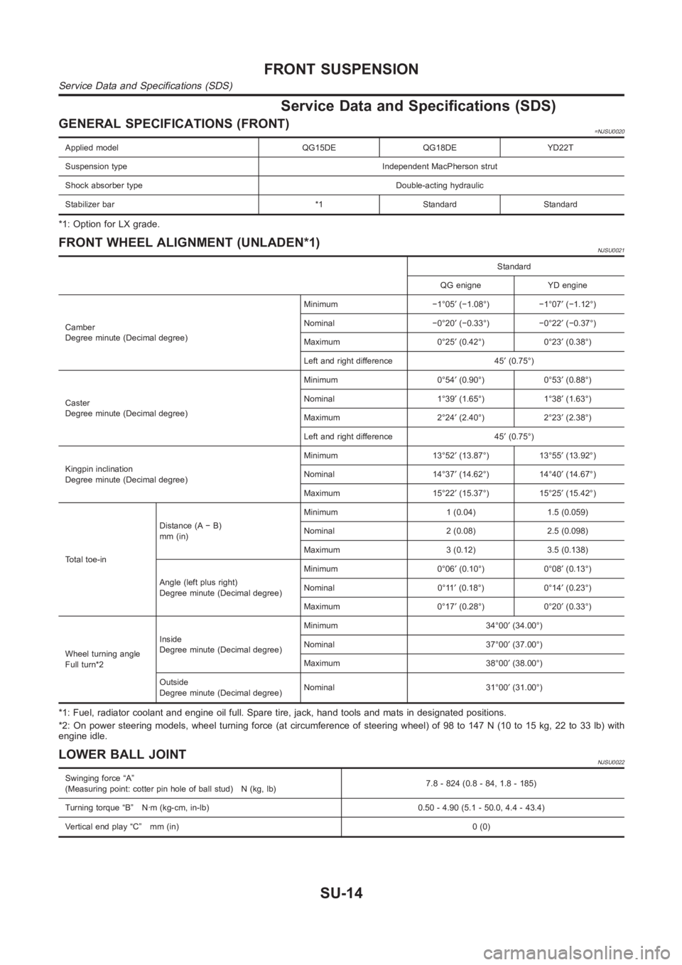
Service Data and Specifications (SDS)
GENERAL SPECIFICATIONS (FRONT)=NJSU0020
Applied model QG15DE QG18DE YD22T
Suspension type Independent MacPherson strut
Shock absorber type Double-acting hydraulic
Stabilizer bar *1 Standard Standard
*1: Option for LX grade.
FRONT WHEEL ALIGNMENT (UNLADEN*1)NJSU0021
Standard
QG enigne YD engine
Camber
Degree minute (Decimal degree)Minimum −1°05′(−1.08°) −1°07′(−1.12°)
Nominal −0°20′(−0.33°) −0°22′(−0.37°)
Maximum 0°25′(0.42°) 0°23′(0.38°)
Left and right difference 45′(0.75°)
Caster
Degree minute (Decimal degree)Minimum 0°54′(0.90°) 0°53′(0.88°)
Nominal 1°39′(1.65°) 1°38′(1.63°)
Maximum 2°24′(2.40°) 2°23′(2.38°)
Left and right difference 45′(0.75°)
Kingpin inclination
Degree minute (Decimal degree)Minimum 13°52′(13.87°) 13°55′(13.92°)
Nominal 14°37′(14.62°) 14°40′(14.67°)
Maximum 15°22′(15.37°) 15°25′(15.42°)
Total toe-inDistance (A − B)
mm (in)Minimum 1 (0.04) 1.5 (0.059)
Nominal 2 (0.08) 2.5 (0.098)
Maximum 3 (0.12) 3.5 (0.138)
Angle (left plus right)
Degree minute (Decimal degree)Minimum 0°06′(0.10°) 0°08′(0.13°)
Nominal 0°11′(0.18°) 0°14′(0.23°)
Maximum 0°17′(0.28°) 0°20′(0.33°)
Wheel turning angle
Full turn*2Inside
Degree minute (Decimal degree)Minimum 34°00′(34.00°)
Nominal 37°00′(37.00°)
Maximum 38°00′(38.00°)
Outside
Degree minute (Decimal degree)Nominal 31°00′(31.00°)
*1: Fuel, radiator coolant and engine oil full. Spare tire, jack, hand tools and mats in designated positions.
*2: On power steering models, wheel turning force (at circumference of steering wheel) of 98 to 147 N (10 to 15 kg, 22 to 33 lb) with
engine idle.
LOWER BALL JOINTNJSU0022
Swinging force “A”
(Measuring point: cotter pin hole of ball stud) N (kg, lb)7.8 - 824 (0.8 - 84, 1.8 - 185)
Turning torque “B” N·m (kg-cm, in-lb) 0.50 - 4.90 (5.1 - 50.0, 4.4 - 43.4)
Vertical end play “C” mm (in)0(0)
FRONT SUSPENSION
Service Data and Specifications (SDS)
SU-14
Page 2499 of 3189
RemovalNJEL0060S02011. Remove cowl top seal rubber and cowl top cover.
2. Remove wiper motor connector.
3. Remove 3 screws that secure wiper motor and wiper frame.
4. Detach wiper motor from wiper linkage at ball joint.
5. Remove wiper linkage.
Be careful not to break ball joint rubber boot.
InstallationNJEL0060S0202Grease ball joint portion before installation.
1. Installation is the reverse order of removal.
YEL822D
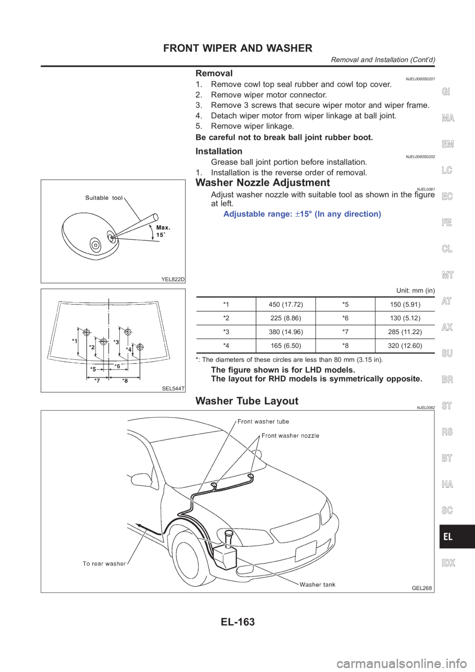
Washer Nozzle AdjustmentNJEL0061Adjust washer nozzle with suitable tool as shown in the figure
at left.
Adjustable range:±15° (In any direction)
SEL544T
Unit: mm (in)
*1 450 (17.72) *5 150 (5.91)
*2 225 (8.86) *6 130 (5.12)
*3 380 (14.96) *7 285 (11.22)
*4 165 (6.50) *8 320 (12.60)
*: The diameters of these circles are less than 80 mm (3.15 in).
The figure shown is for LHD models.
The layout for RHD models is symmetrically opposite.
Washer Tube LayoutNJEL0062
GEL268
GI
MA
EM
LC
EC
FE
CL
MT
AT
AX
SU
BR
ST
RS
BT
HA
SC
IDX
FRONT WIPER AND WASHER
Removal and Installation (Cont’d)
EL-163
Page 3147 of 3189
Special Service ToolsNJST0004
Tool number
Tool nameDescription
KV48100700
Torque adapter
NT169
Measuring pinion rotating torque
KV48102500
Pressure gauge adapter
NT542
Measuring oil pressure
ST27180001
Steering wheel puller
NT544
Removing steering wheel
HT72520000
Ball joint remover
NT546
Removing ball joint
a: 33 mm (1.30 in)
b: 50 mm (1.97 in)
r: R11.5 mm (0.453 in)
KV48103500
Pressure gauge
NT547
Measuring oil pressure
KV48104400
Rack seal ring reformer
NT550
Reforming teflon ring
a: 50 mm (1.97 in) dia.
b: 36 mm (1.42 in) dia.
c: 100 mm (3.94 in)
ST3127S000
1 GG91030000
Torque wrench
2 HT62940000
Socket adapter
3 HT62900000
Socket adapter
NT541
Measuring turning torque
GI
MA
EM
LC
EC
FE
CL
MT
AT
AX
SU
BR
RS
BT
HA
SC
EL
IDX
PREPARATION
Special Service Tools
ST-3
Page 3149 of 3189
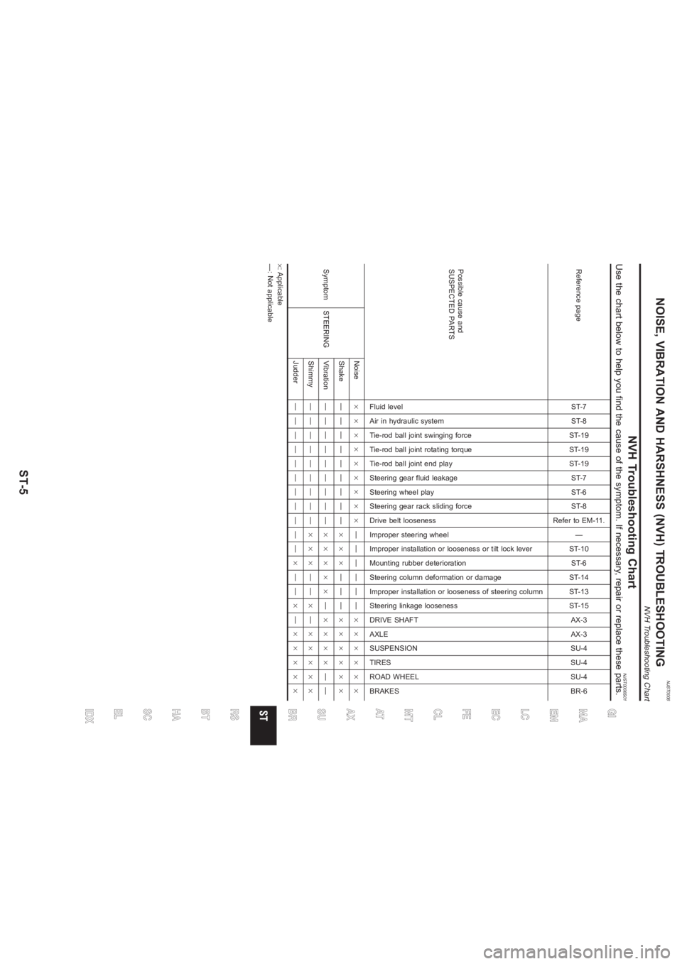
NJST0006
NVH Troubleshooting Chart
NJST0006S01
Use the chart below to help you find the cause of the symptom. If necessary, repair or replace these parts.Reference page
ST-7
ST-8
ST-19
ST-19
ST-19
ST-7
ST-6
ST-8
Refer to EM-11.
—
ST-10
ST-6
ST-14
ST-13
ST-15
AX-3
AX-3
SU-4
SU-4
SU-4
BR-6
Possible cause and
SUSPECTED PARTS
Fluid level
Air in hydraulic system
Tie-rod ball joint swinging force
Tie-rod ball joint rotating torque
Tie-rod ball joint end play
Steering gear fluid leakage
Steering wheel play
Steering gear rack sliding force
Drive belt looseness
Improper steering wheel
Improper installation or looseness or tilt lock lever
Mounting rubber deterioration
Steering column deformation or damage
Improper installation or looseness of steering column
Steering linkage looseness
DRIVE SHAFT
AXLE
SUSPENSION
TIRES
ROAD WHEEL
BRAKES
Symptom STEERINGNoise×××××××××——————××××××
Shake —————————×××———××××××
Vibration —————————×××××—××××——
Shimmy —————————×××——×—×××××
Judder———————————×——×—×××××
×: Applicable
—: Not applicable
GI
MA
EM
LC
EC
FE
CL
MT
AT
AX
SU
BRRS
BT
HA
SC
EL
IDX
NOISE, VIBRATION AND HARSHNESS (NVH) TROUBLESHOOTING
NVH Troubleshooting Chart
ST-5
Page 3151 of 3189
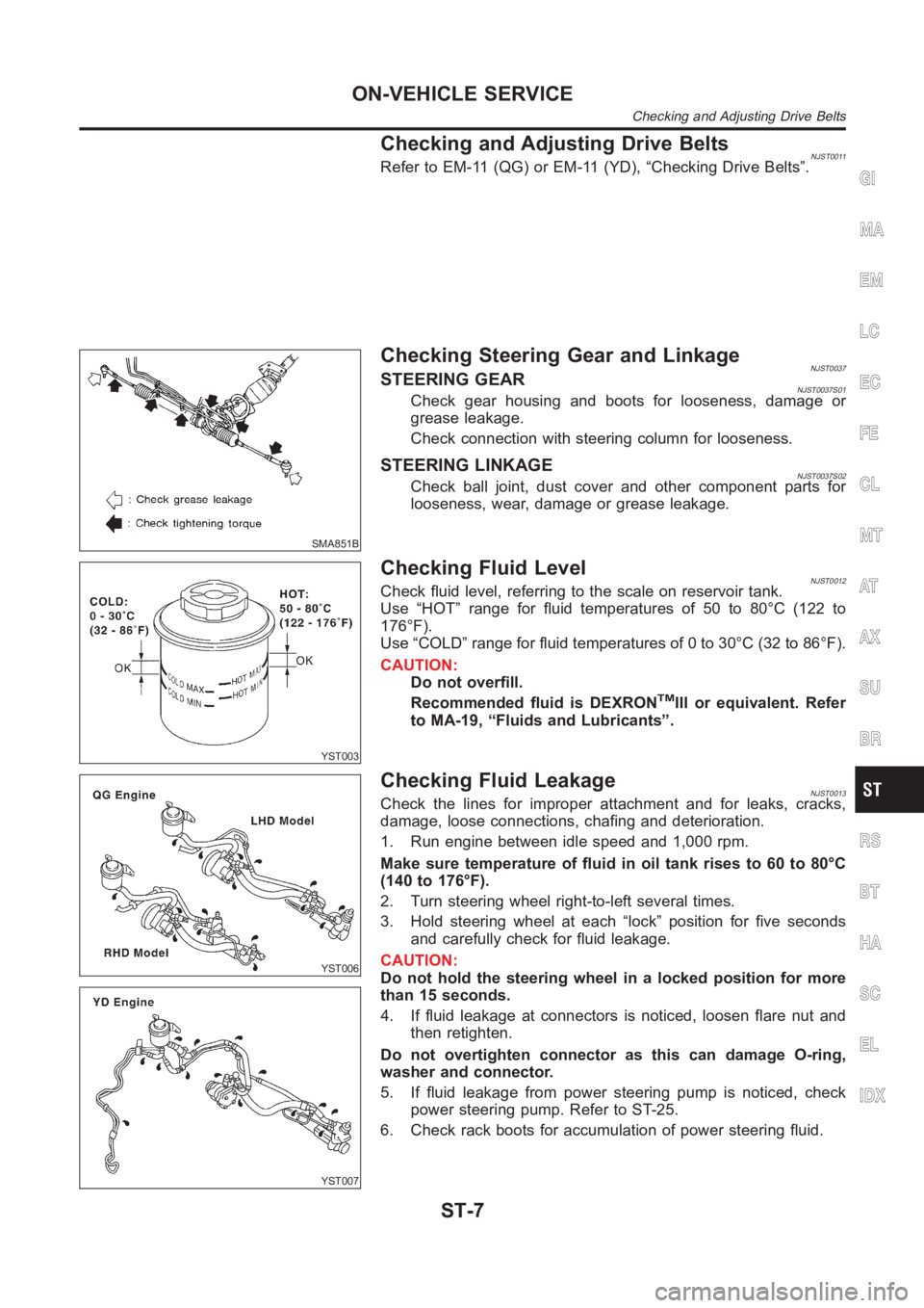
Checking and Adjusting Drive BeltsNJST0011Refer to EM-11 (QG) or EM-11 (YD), “Checking Drive Belts”.
SMA851B
Checking Steering Gear and LinkageNJST0037STEERING GEARNJST0037S01Check gear housing and boots for looseness, damage or
grease leakage.
Check connection with steering column for looseness.
STEERING LINKAGENJST0037S02Check ball joint, dust cover and other component parts for
looseness, wear, damage or grease leakage.
YST003
Checking Fluid LevelNJST0012Check fluid level, referring to the scale on reservoir tank.
Use “HOT” range for fluid temperatures of 50 to 80°C (122 to
176°F).
Use “COLD” range for fluid temperatures of 0 to 30°C (32 to 86°F).
CAUTION:
Do not overfill.
Recommended fluid is DEXRONTMIII or equivalent. Refer
to MA-19, “Fluids and Lubricants”.
YST006
YST007
Checking Fluid LeakageNJST0013Check the lines for improper attachment and for leaks, cracks,
damage, loose connections, chafing and deterioration.
1. Run engine between idle speed and 1,000 rpm.
Make sure temperature of fluid in oil tank rises to 60 to 80°C
(140 to 176°F).
2. Turn steering wheel right-to-left several times.
3. Hold steering wheel at each “lock” position for five seconds
and carefully check for fluid leakage.
CAUTION:
Do not hold the steering wheel in a locked position for more
than 15 seconds.
4. If fluid leakage at connectors is noticed, loosen flare nut and
then retighten.
Do not overtighten connector as this can damage O-ring,
washer and connector.
5. If fluid leakage from power steering pump is noticed, check
power steering pump. Refer to ST-25.
6. Check rack boots for accumulation of power steering fluid.
GI
MA
EM
LC
EC
FE
CL
MT
AT
AX
SU
BR
RS
BT
HA
SC
EL
IDX
ON-VEHICLE SERVICE
Checking and Adjusting Drive Belts
ST-7
Page 3163 of 3189
SST468C
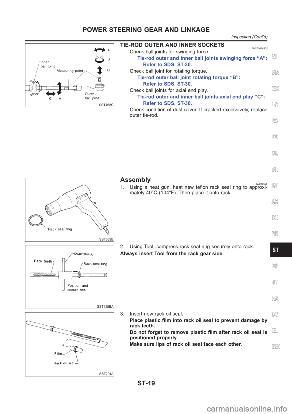
TIE-ROD OUTER AND INNER SOCKETSNJST0024S05Check ball joints for swinging force.
Tie-rod outer and inner ball joints swinging force “A”:
Refer to SDS, ST-30.
Check ball joint for rotating torque.
Tie-rod outer ball joint rotating torque “B”:
Refer to SDS, ST-30.
Check ball joints for axial end play.
Tie-rod outer and inner ball joints axial end play “C”:
Refer to SDS, ST-30.
Check condition of dust cover. If cracked excessively, replace
outer tie-rod.
SST083B
AssemblyNJST00251. Using a heat gun, heat new teflon rack seal ring to approxi-
mately 40°C (104°F). Then place it onto rack.
SST885BA
2. Using Tool, compress rack seal ring securely onto rack.
Always insert Tool from the rack gear side.
SST201A
3. Insert new rack oil seal.
Place plastic film into rack oil seal to prevent damage by
rack teeth.
Do not forget to remove plastic film after rack oil seal is
positioned properly.
Make sure lips of rack oil seal face each other.
GI
MA
EM
LC
EC
FE
CL
MT
AT
AX
SU
BR
RS
BT
HA
SC
EL
IDX
POWER STEERING GEAR AND LINKAGE
Inspection (Cont’d)
ST-19