2003 NISSAN ALMERA N16 electrical
[x] Cancel search: electricalPage 3146 of 3189
Supplemental Restraint System (SRS) “AIR
BAG” and “SEAT BELT PRE-TENSIONER”
NJST0044The Supplemental Restraint System such as “AIR BAG” and “SEAT BELT PRE-TENSIONER” used along with
a seat belt, helps to reduce the risk or severity of injury to the driver and front passenger for certain types of
collision. The SRS system composition which is available to NISSAN MODEL N16 is as follows (The compo-
sition varies according to the destination and optional equipment.):
For a frontal collision
The Supplemental Restraint System consists of driver air bag module (located in the center of the steer-
ing wheel), front passenger air bag module (located on the instrument panel on passenger side), front seat
belt pre-tensioners, a diagnosis sensor unit, warning lamp, wiring harness and spiral cable.
For a side collision
The Supplemental Restraint System consists of front side air bag module (located in the outer side of front
seat), side air bag (satellite) sensor, diagnosis sensor unit (one of components of air bags for a frontal
collision), wiring harness, warning lamp (one of components of air bags for a frontal collision).
Information necessary to service the system safely is included in theRS sectionof this Service Manual.
WARNING:
To avoid rendering the SRS inoperative, which could increase the risk of personal injury or death
in the event of a collision which would result in air bag inflation, all maintenance should be per-
formed by an authorized NISSAN dealer.
Improper maintenance, including incorrect removal and installation of the SRS, can lead to per-
sonal injury caused by unintentional activation of the system. For removalofSpiralCableandAir
Bag Module, see the RS section.
Do not use electrical test equipment on any circuit related to the SRS unless instructed to in this
Service Manual. SRS wiring harnesses (except “SEAT BELT PRE-TENSIONER” connector) can be
identified by yellow harness connector.
Precautions for Steering SystemNJST0003Before disassembly, thoroughly clean the outside of the unit.
Disassembly should be done in a clean work area. It is important to prevent the internal parts from
becoming contaminated by dirt or other foreign matter.
Place disassembled parts in order, on a parts rack, for easier and proper assembly.
Use nylon cloths or paper towels to clean the parts; common shop rags can leave lint that might
interfere with their operation.
Before inspection or reassembly, carefully clean all parts with a generalpurpose, non-flammable
solvent.
Before assembly, apply a coat of recommended power steering fluid* to hydraulic parts. Vaseline
may be applied to O-rings and seals. Do not use any grease.
Replace all gaskets, seals and O-rings. Avoid damaging O-rings, seals andgaskets during instal-
lation. Perform functional tests whenever designated.
*: DEXRON
TMIII or equivalent. Refer to MA-19, “Fluids and Lubricants”.
PRECAUTIONS
Supplemental Restraint System (SRS) “AIR BAG” and “SEAT BELT PRE-TENSIONER”
ST-2
Page 3178 of 3189
COOL/F - Wiring diagram
(QG engine)................................EC-328, EC-601
COOL/F - Wiring diagram (YD engine) ........EC-130
Coolant mixture ratio......................................MA-21
Cooling circuit (engine).............................LC-12, 36
Cooling fan control (YD engine)...................EC-130
Cooling fan control system .......................LC-17, 42
Cooling fan motor (QG engine) .....EC-335, EC-608
Coupling sleeve (M/T)........................MT-31, 55, 93
Crankcase emission control system -
See positive crankcase ventilation
(YD engine).................................................EC-19
Crankcase ventilation system - See
Positive crankcase ventilation
(QG engine)................................EC-403, EC-722
Crankcase ventilation system - See
Positive crankcase ventilation
(YD engine).................................................EC-19
Crankshaft (QG engine).................................EM-71
Crankshaft (YD engine) .................................EM-75
Crankshaft position sensor (POS)
(QG engine)................................EC-235, EC-556
Crankshaft position sensor (TDC)
(YD engine).................................................EC-99
Cylinder block (QG engine) ...........................EM-70
Cylinder block (YD engine) ............................EM-66
Cylinder block boring (QG engine) ................EM-88
Cylinder block boring(QR) .............................EM-89
Cylinder head (QG engine)............................EM-57
Cylinder head (YD engine) ............................EM-45
Cylinder head bolt tightening
(QG engine)................................................EM-59
D
Data link connector
(QG engine) ...EC-398, EC-399, EC-717, EC-718
Data link connector for Consult
(QG engine)..................................EC-90, EC-468
Data link connector for Consult
(YD engine).................................................EC-39
Daytime light system.......................................EL-46
DEF - Wiring diagram ...................................EL-176
Diagnosis sensor unit .....................................RS-26
Diagnostic trouble code (DTC) for OBD
system (QG engine) ......................EC-10, EC-39,
EC-407, EC-430
Diagnostic trouble code (DTC) for OBD
system (YD engine) ................................EC-4, 34
Diagnostic trouble code (DTC) inspec-
tion priority chart (QG engine) .....EC-62, EC-441
Differential gear (FF M/T) ....MT-31, 43, 55, 93, 107
Dimensions <0011001100110011001100110011001100110011001100110011001100110011001100110011001100110011001100110011001100110011001100110011001100110011001100110011001100110011001100110011001100110011001100110011001100
1100110011[.GI-44
Dome light - See Interior lamp .......................EL-80
Door glass <0011001100110011001100110011001100110011001100110011001100110011001100110011001100110011001100110011001100110011001100110011001100110011001100110011001100110011001100110011001100110011001100110011001100
11001100110011[.BT-17
Door lock <0011001100110011001100110011001100110011001100110011001100110011001100110011001100110011001100110011001100110011001100110011001100110011001100110011001100110011001100110011001100110011001100110011001100
110011001100110011[..BT-21
Door mirror <0011001100110011001100110011001100110011001100110011001100110011001100110011001100110011001100110011001100110011001100110011001100110011001100110011001100110011001100110011001100110011001100110011001100
1100110011[.BT-72
Door trim <0011001100110011001100110011001100110011001100110011001100110011001100110011001100110011001100110011001100110011001100110011001100110011001100110011001100110011001100110011001100110011001100110011001100
110011001100110011[..BT-39
Door, front <0011001100110011001100110011001100110011001100110011001100110011001100110011001100110011001100110011001100110011001100110011001100110011001100110011001100110011001100110011001100110011001100110011001100
1100110011[..BT-16
Door, rear <0011001100110011001100110011001100110011001100110011001100110011001100110011001100110011001100110011001100110011001100110011001100110011001100110011001100110011001100110011001100110011001100110011001100
11001100110011[..BT-16Drive belt (QG engine) ...................................EM-11
Drive shaft (front)............................................AX-10
Dropping resistor (A/T) ....................AT-171, AT-395
DTC work support (QG engine) .....................EC-97
Dual pressure switch (manual A/C) ...............HA-12
Dual pressure switch ......ATC-15, ATC-86, ATC-144
Duct and grilles...........................................ATC-131
E
ECCS-D control module
(YD engine) ........EC-66, 116, 175, 177, 181, 183
ECM input/output signal
(QG engine)..................................EC-81, EC-460
ECM input/output signal (YD engine) ............EC-66
ECM power supply
(QG engine) ...EC-111, EC-269, EC-488, EC-573
ECM/PW - Wiring diagram
(QG engine)................................EC-270, EC-574
ECTS - Wiring diagram
(QG engine)................................EC-147, EC-505
ECTS - Wiring diagram (YD engine)..............EC-84
EGR volume control valve (YD engine) .......EC-197
EGRC1 - Wiring diagram (YD engine) .........EC-199
Electric sun roof ............................................EL-249
Electric throttle control actuator
(QG engine) ................EC-277, EC-279, EC-292,
EC-577, EC-580, EC-593
Electrical diagnoses.........................................GI-22
Electrical load signal circuit
(QG engine)................................EC-393, EC-712
Electrical unit ................................................Foldout
Electrical units location .................................EL-543
Electronic fuel injection pump
(YD engine) ...............EC-25, 118, 124, 145, 151,
157, 163, 169, 185
Electronic ignition (EI) system
(QG engine)..................................EC-25, EC-420
Engine compartment .......................................BT-75
Engine control circuit diagram
(QG engine)..................................EC-79, EC-458
Engine control circuit diagram
(YD engine).................................................EC-14
Engine control component parts loca-
tion (QG engine)...........................EC-75, EC-454
Engine control component parts loca-
tion (YD engine) ..........................................EC-11
Engine control module (ECM)
(QG engine)................................EC-266, EC-570
Engine control module (ECM)
(YD engine) ........EC-66, 116, 175, 177, 181, 183
Engine control system diagram and
chart (QG engine) ........................EC-21, EC-416
Engine control system diagram and
chart (YD engine) .......................................EC-15
Engine coolant temperature sensor
(ECTS) (QG engine) ..................EC-145, EC-503
Engine coolant temperature sensor
(ECTS) (YD engine) ...................................EC-84
ALPHABETICAL INDEX
IDX-4
Page 3180 of 3189

Heated oxygen sensor 2 heater
(QG engine)................................EC-129, EC-640
Heated seat<0011001100110011001100110011001100110011001100110011001100110011001100110011001100110011001100110011001100110011001100110011001100110011001100110011001100110011001100110011001100110011001100110011001100
110028002f[-247
HEATER - Wiring diagram (manual
A/C) <0011001100110011001100110011001100110011001100110011001100110011001100110011001100110011001100110011001100110011001100110011001100110011001100110011001100110011001100110011001100110011001100110011001100
1100110011001100110011001100110011[..HA-23
Heater and cooling unit (Heater core)
(manual A/C) ...............................................HA-87
Heater and cooling unit (Heater core)........ATC-123
Heater unit (heater core) ............................ATC-130
Height (Dimensions) ........................................GI-44
HFC134a (R134a) system precaution
(manual A/C) .................................................HA-2
HFC134a (R134a) system precaution............ATC-4
HFC134a (R134a) system service pro-
cedure (manual A/C)...................................HA-77
HFC134a (R134a) system service
procedure ................................................ATC-133
HFC134a (R134a) system service tools
(manual A/C) ...............................................HA-10
HFC134a (R134a) system service tools ......ATC-11
HFC134a system service equipment
precaution (manual A/C) ...............................HA-6
HFC134a system service equipment
precaution <0011001100110011001100110011001100110011001100110011001100110011001100110011001100110011001100110011001100110011001100110011001100110011001100110011001100110011001100110011001100110011001100110011001100
110024>TC-7
HO2S1 - Wiring diaram
(QG engine) ................EC-152, EC-159, EC-169,
EC-510, EC-516
HO2S1H - Wiring diagram (QG engine) ......EC-125
HO2S2 - Wiring diagram
(QG engine) ................EC-175, EC-182, EC-312,
EC-320, EC-522
HO2S2H - Wiring diagram (QG engine) ......EC-131
Hood<0011001100110011001100110011001100110011001100110011001100110011001100110011001100110011001100110011001100110011001100110011001100110011001100110011001100110011001100110011001100110011001100110011001100
1100110011001100110011001100110011[.......BT-7
HORN - Wiring diagram................................EL-170
Horn <0011001100110011001100110011001100110011001100110011001100110011001100110011001100110011001100110011001100110011001100110011001100110011001100110011001100110011001100110011001100110011001100110011001100
1100110011001100110011001100110011[...EL-170
How to erase DTC for OBD system
(QG engine)..................................EC-48, EC-431
How to erase DTC for OBD system
(YD engine).................................................EC-34
HSEAT - Wiring diagram ......................EL-246, 247
I
IATS - Wiring diagram (QG engine) .............EC-142
IATSEN - Wiring diagram (QG engine) ........EC-646
Identification plate............................................GI-41
Identification .....................................ATC-9, ATC-10
Idle air volume learning
(QG engine)..................................EC-31, EC-426
Idle speed (QG engine) ...................EC-65, EC-444
Idle speed (YD engine) ..................................EC-48
Ignition coil (QG engine) ................EC-366, EC-662
Ignition coil (QG engine) ................................EM-24
Ignition control system
(QG engine)................................EC-366, EC-662
Ignition timing (QG engine)..............EC-65, EC-444
IGNSYS - Wiring diagram
(QG engine)................................EC-367, EC-663
ILL - Wiring diagram .......................................EL-76
Illumination <0011001100110011001100110011001100110011001100110011001100110011001100110011001100110011001100110011001100110011001100110011001100110011001100110011001100110011001100110011001100110011001100110011001100
11[...EL-75In vehicle sensor ........ATC-103, ATC-105, ATC-117
INJECT - Wiring diagram
(QG engine)................................EC-377, EC-696
Injection nozzle (YD engine) ..........................EC-21
Injector (QG engine) ......................EC-376, EC-695
Input shaft (FF M/T).....................MT-36, 64, 93, 98
Instrument panel .............................................BT-25
INT/L - Wiring diagram..................................EL-108
Intake air temperature sensor
(QG engine)................................EC-141, EC-645
Intake door control linkage adjustment ........ATC-67
Intake door motor .........................ATC-66, ATC-122
Intake manifold (QG engine) .........................EM-16
Intake sensor ..............................ATC-109, ATC-119
Intake valve timing control
(QG engine) .................EC-120, EC-273, EC-685
Intake valve timing control solenoid
valve (QG engine) ......................EC-273, EC-685
Interior lamp on-off control........................EL-81, 83
Interior lamp <0011001100110011001100110011001100110011001100110011001100110011001100110011001100110011001100110011001100110011001100110011001100110011001100110011001100110011001100110011001100110011001100110011001100
11[.EL-80
Interior <0011001100110011001100110011001100110011001100110011001100110011001100110011001100110011001100110011001100110011001100110011001100110011001100110011001100110011001100110011001100110011001100110011001100
110011001100110011[......BT-31
ISO 15031-2 Terminology ................................GI-51
ISO 15031-5 Mode 1 - 9 (QG engine) ...........EC-36
IVC - Wiring diagram (QG engine)...............EC-274
IVC/V - Wiring diagram (QG engine) ...........EC-687
J
Jacking points ..................................................GI-46
Joint connector (J/C) ....................................Foldout
Junction box (J/B).........................................Foldout
K
Keyless entry system - See Multi-re-
mote control system ..................................EL-352
Knock sensor (KS) (QG engine) ....EC-231, EC-552
Knuckle spindle ................................................AX-5
KS - Wiring diagram
(QG engine)................................EC-232, EC-553
L
LAN system circuit........................................ATC-57
Length (Dimensions) .......................................GI-44
License lamp <0011001100110011001100110011001100110011001100110011001100110011001100110011001100110011001100110011001100110011001100110011001100110011001100110011001100110011001100110011001100110011001100110011001100
110028[L-55
Lifting points ....................................................GI-47
Line pressure solenoid valve ........................AT-159
Line pressure test (A/T) .....................AT-67, AT-266
Liquid gasket application (QG engine) ............EM-4
Liquid gasket application (YD engine) .............EM-3
LOAD - Wiring diagram
(QG engine)................................EC-394, EC-713
Location of electrical units ............................EL-543
Lock, door <0011001100110011001100110011001100110011001100110011001100110011001100110011001100110011001100110011001100110011001100110011001100110011001100110011001100110011001100110011001100110011001100110011001100
11001100110011[.BT-21
Lubricant (R134a) A/C (manual A/C) .............HA-79
Lubricant (R134a) A/C......................ATC-5, ATC-20
ALPHABETICAL INDEX
IDX-6
Page 3188 of 3189
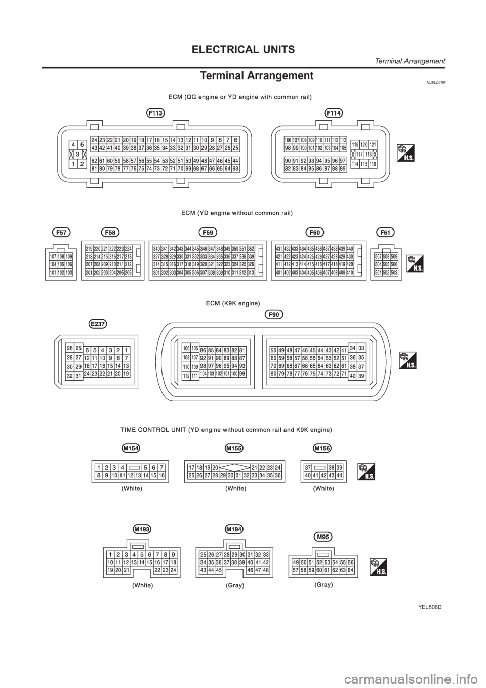
Terminal ArrangementNJEL0495
YEL806D
ELECTRICAL UNITS
Terminal Arrangement