2003 NISSAN ALMERA N16 Fuel fuse
[x] Cancel search: Fuel fusePage 58 of 3189
NJMA0036
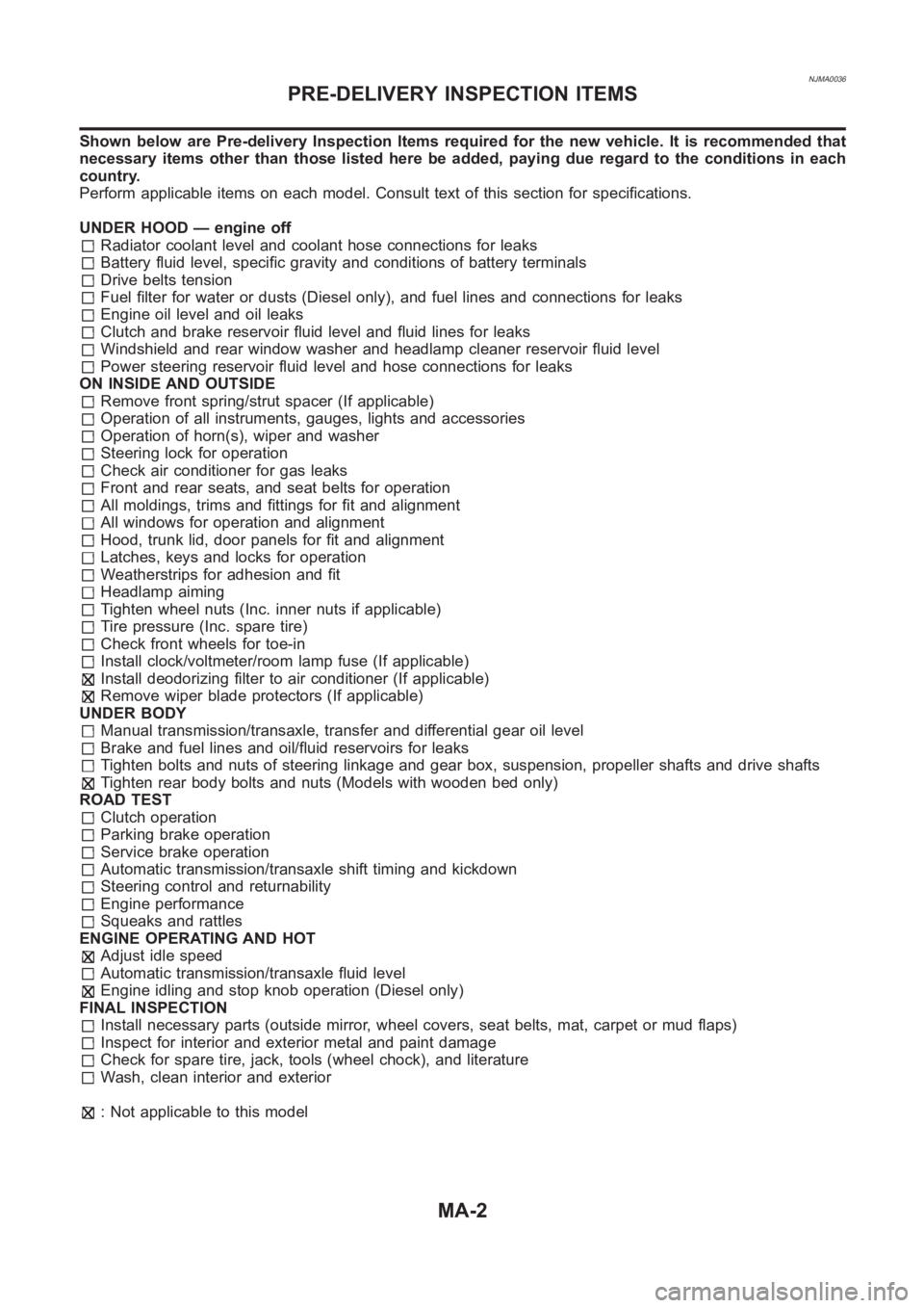
Shown below are Pre-delivery Inspection Items required for the new vehicle. It is recommended that
necessary items other than those listed here be added, paying due regard tothe conditions in each
country.
Perform applicable items on each model. Consult text of this section for specifications.
UNDER HOOD — engine off
Radiator coolant level and coolant hose connections for leaks
Battery fluid level, specific gravity and conditions of battery terminals
Drive belts tension
Fuel filter for water or dusts (Diesel only), and fuel lines and connections for leaks
Engine oil level and oil leaks
Clutch and brake reservoir fluid level and fluid lines for leaks
Windshield and rear window washer and headlamp cleaner reservoir fluid level
Power steering reservoir fluid level and hose connections for leaks
ON INSIDE AND OUTSIDE
Remove front spring/strut spacer (If applicable)
Operation of all instruments, gauges, lights and accessories
Operation of horn(s), wiper and washer
Steering lock for operation
Check air conditioner for gas leaks
Front and rear seats, and seat belts for operation
All moldings, trims and fittings for fit and alignment
All windows for operation and alignment
Hood, trunk lid, door panels for fit and alignment
Latches, keys and locks for operation
Weatherstrips for adhesion and fit
Headlamp aiming
Tighten wheel nuts (Inc. inner nuts if applicable)
Tire pressure (Inc. spare tire)
Check front wheels for toe-in
Install clock/voltmeter/room lamp fuse (If applicable)
Install deodorizing filter to air conditioner (If applicable)
Remove wiper blade protectors (If applicable)
UNDER BODY
Manual transmission/transaxle, transfer and differential gear oil level
Brake and fuel lines and oil/fluid reservoirs for leaks
Tighten bolts and nuts of steering linkage and gear box, suspension, propeller shafts and drive shafts
Tighten rear body bolts and nuts (Models with wooden bed only)
ROAD TEST
Clutch operation
Parking brake operation
Service brake operation
Automatic transmission/transaxle shift timing and kickdown
Steering control and returnability
Engine performance
Squeaks and rattles
ENGINE OPERATING AND HOT
Adjust idle speed
Automatic transmission/transaxle fluid level
Engine idling and stop knob operation (Diesel only)
FINAL INSPECTION
Install necessary parts (outside mirror, wheel covers, seat belts, mat, carpet or mud flaps)
Inspect for interior and exterior metal and paint damage
Check for spare tire, jack, tools (wheel chock), and literature
Wash, clean interior and exterior
: Not applicable to this model
PRE-DELIVERY INSPECTION ITEMS
MA-2
Page 193 of 3189
NJEM0053
JEM111G
1. Warm up engine.
2. Turn ignition switch OFF.
3. Using CONSULT-II, make sure no error codes are indicated for
self-diagnosis items. Refer to EC-39, “CONSULT-II Inspection
Procedure”.
Do not disconnect CONSULT-II until the end of this operation;
it will be used to check engine rpm and for error detection at
the end of this operation.
4. Disconnect the negative battery terminal.
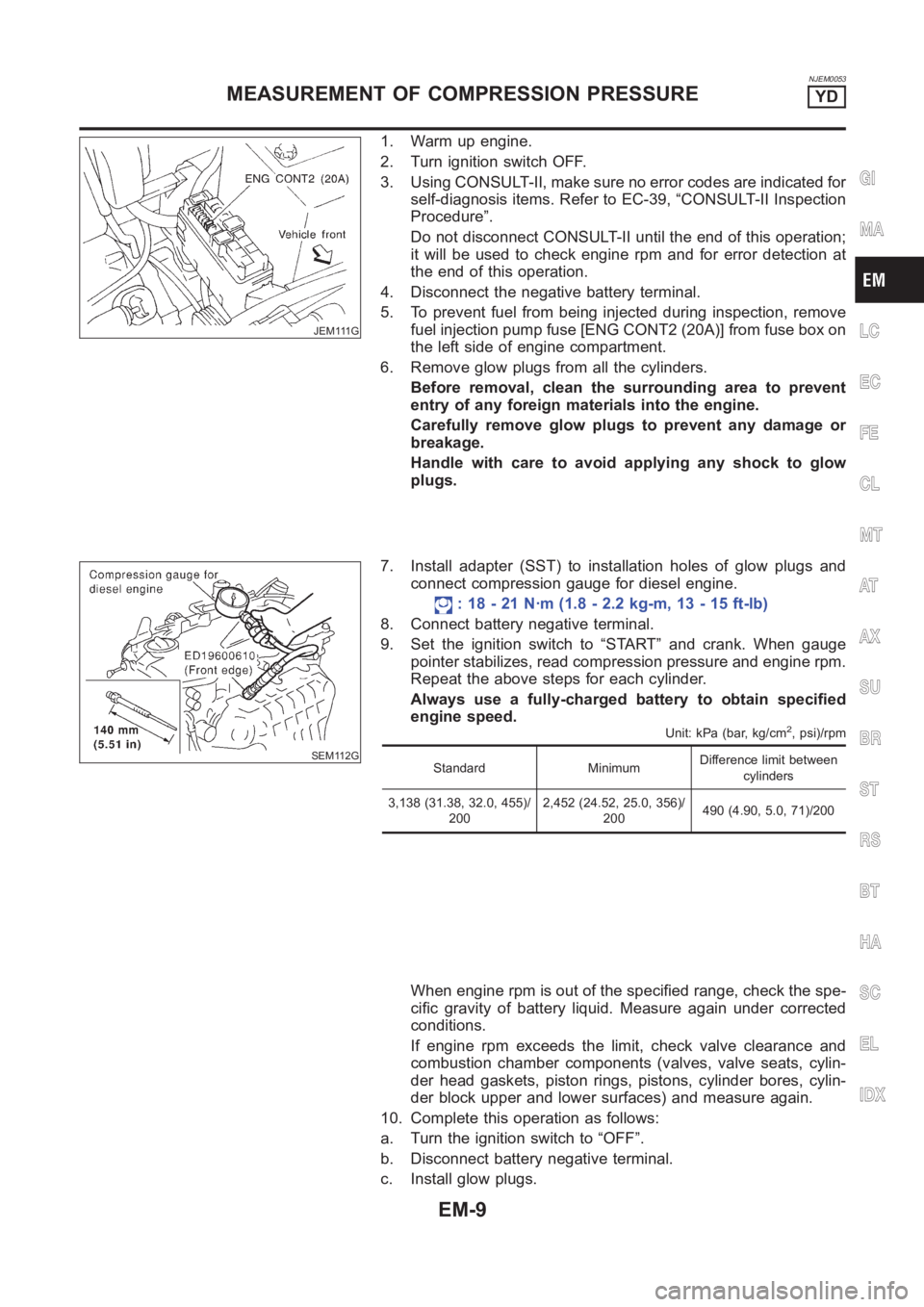
5. To prevent fuel from being injected during inspection, remove
fuel injection pump fuse [ENG CONT2 (20A)] from fuse box on
the left side of engine compartment.
6. Remove glow plugs from all the cylinders.
Before removal, clean the surrounding area to prevent
entry of any foreign materials into the engine.
Carefully remove glow plugs to prevent any damage or
breakage.
Handle with care to avoid applying any shock to glow
plugs.
SEM112G
7. Install adapter (SST) to installation holes of glow plugs and
connect compression gauge for diesel engine.
: 18 - 21 N·m (1.8 - 2.2 kg-m, 13 - 15 ft-lb)
8. Connect battery negative terminal.
9. Set the ignition switch to “START” and crank. When gauge
pointer stabilizes, read compression pressure and engine rpm.
Repeat the above steps for each cylinder.
Always use a fully-charged battery to obtain specified
engine speed.
Unit: kPa (bar, kg/cm2, psi)/rpm
Standard MinimumDifference limit between
cylinders
3,138 (31.38, 32.0, 455)/
2002,452 (24.52, 25.0, 356)/
200490 (4.90, 5.0, 71)/200
When engine rpm is out of the specified range, check the spe-
cific gravity of battery liquid. Measure again under corrected
conditions.
If engine rpm exceeds the limit, check valve clearance and
combustion chamber components (valves, valve seats, cylin-
der head gaskets, piston rings, pistons, cylinder bores, cylin-
der block upper and lower surfaces) and measure again.
10. Complete this operation as follows:
a. Turn the ignition switch to “OFF”.
b. Disconnect battery negative terminal.
c. Install glow plugs.
GI
MA
LC
EC
FE
CL
MT
AT
AX
SU
BR
ST
RS
BT
HA
SC
EL
IDX
MEASUREMENT OF COMPRESSION PRESSUREYD
EM-9
Page 194 of 3189
![NISSAN ALMERA N16 2003 Electronic Repair Manual d. Install fuel injection pump fuse [ENG CONT2 (20A)].
e. Connect battery negative terminal.
f. Using CONSULT-II make sure no error code is indicated for
items of self-diagnosis. Refer to EC-39, “CO](/manual-img/5/57350/w960_57350-193.png "NISSAN ALMERA N16 2003 Electronic Repair Manual d. Install fuel injection pump fuse [ENG CONT2 (20A)].
e. Connect battery negative terminal.
f. Using CONSULT-II make sure no error code is indicated for
items of self-diagnosis. Refer to EC-39, “CO")
d. Install fuel injection pump fuse [ENG CONT2 (20A)].
e. Connect battery negative terminal.
f. Using CONSULT-II make sure no error code is indicated for
items of self-diagnosis. Refer to EC-39, “CONSULT-II Inspec-
tion Procedure”.
MEASUREMENT OF COMPRESSION PRESSUREYD
EM-10
Page 364 of 3189
![NISSAN ALMERA N16 2003 Electronic Repair Manual EC-34
[QG (WITH EURO-OBD)]
BASIC SERVICE PROCEDURE
DIAGNOSTIC PROCEDURE
If idle air volume learning cannot be performed successfully, proceed as follows:
1.Check that throttle valve is fully closed.
2](/manual-img/5/57350/w960_57350-363.png "NISSAN ALMERA N16 2003 Electronic Repair Manual EC-34
[QG (WITH EURO-OBD)]
BASIC SERVICE PROCEDURE
DIAGNOSTIC PROCEDURE
If idle air volume learning cannot be performed successfully, proceed as follows:
1.Check that throttle valve is fully closed.
2")
EC-34
[QG (WITH EURO-OBD)]
BASIC SERVICE PROCEDURE
DIAGNOSTIC PROCEDURE
If idle air volume learning cannot be performed successfully, proceed as follows:
1.Check that throttle valve is fully closed.
2.Check PCV valve operation.
3.Check that downstream of throttle valve is free from air leakage.
4.When the above three items check out OK, engine component parts and their installation condi-
tion are questionable. Check and eliminate the cause of the incident.
It is useful to perform EC-105, "
TROUBLE DIAGNOSIS - SPECIFICATION VALUE" .
5.If any of the following conditions occur after the engine has started, eliminate the cause of the
incident and perform “Idle air volume learning” all over again:
–Engine stalls.
–Erroneous idle.
Fuel Pressure CheckEBS00K3E
FUEL PRESSURE RELEASE
Before disconnecting fuel line, release fuel pressure from fuel line to eliminate danger.
NOTE:
Prepare pans or saucers under the disconnected fuel line because the fuel may spill out. The fuel pres-
sure cannot be completely released because N16 models do not have fuel return system.
With CONSULT-II
1. Turn ignition switch “ON”.
2. Perform “FUEL PRESSURE RELEASE” in “WORK SUPPORT”
mode with CONSULT-II.
3. Start engine.
4. After engine stalls, crank it two or three times to release all fuel
pressure.
5. Turn ignition switch “OFF”.
Without CONSULT-II
1. Remove fuel pump fuse located in fuse box.
2. Start engine.
3. After engine stalls, crank it two or three times to release all fuel
pressure.
4. Turn ignition switch “OFF”.
5. Reinstall fuel pump fuse after servicing fuel system.
FUEL PRESSURE CHECK
NOTE:
●When reconnecting fuel line, always use new clamps.
●Make sure that clamp screw does not contact adjacent parts.
●Use a torque driver to tighten clamps.
●Use Pressure Gauge to check fuel pressure.
1. Release fuel pressure to zero. Refer to EC-34, "
FUEL PRESSURE RELEASE" .
SEF214Y
MBIB0262E
Page 714 of 3189
![NISSAN ALMERA N16 2003 Electronic Repair Manual EC-384
[QG (WITH EURO-OBD)]
FUEL PUMP CIRCUIT
3. DETECT MALFUNCTIONING PART
Check the following.
●Fuse block (J/B) connector B4
●10A fuse
●15A fuse
●Harness for open or short between fuel pump](/manual-img/5/57350/w960_57350-713.png "NISSAN ALMERA N16 2003 Electronic Repair Manual EC-384
[QG (WITH EURO-OBD)]
FUEL PUMP CIRCUIT
3. DETECT MALFUNCTIONING PART
Check the following.
●Fuse block (J/B) connector B4
●10A fuse
●15A fuse
●Harness for open or short between fuel pump")
EC-384
[QG (WITH EURO-OBD)]
FUEL PUMP CIRCUIT
3. DETECT MALFUNCTIONING PART
Check the following.
●Fuse block (J/B) connector B4
●10A fuse
●15A fuse
●Harness for open or short between fuel pump relay and fuse
>> Repair open circuit or short to ground or short to power in harness or connectors.
4. CHECK FUEL PUMP POWER SUPPLY AND GROUND CIRCUIT FOR OPEN AND SHORT
1. Turn ignition switch “OFF”.
2. Disconnect fuel level sensor unit and fuel pump harness con-
nector.
3. Check harness continuity between fuel pump relay terminal 3
and fuel level sensor unit and fuel pump terminal 5, fuel level
sensor unit and fuel pump terminal 3 and body ground.
Refer to Wiring Diagram.
4. Also check harness for short to ground and short to power.
OK or NG
OK >> GO TO 6.
NG >> GO TO 5.
5. DETECT MALFUNCTIONING PART
Check the following.
●Harness connectors B61, D91 (Hatchback models with power door lock)
●Harness connectors B62, D92 (Hatchback models without power door lock)
●Harness for open or short between fuel level sensor unit and fuel pump and fuel pump relay
●Harness for open or short between fuel level sensor unit and fuel pump and body ground
>> Repair open circuit or short to ground or short to power in harness or connectors.
6. CHECK FUEL PUMP RELAY OUTPUT SIGNAL CIRCUIT FOR OPEN AND SHORT
1. Disconnect ECM harness connector.
2. Check harness continuity between ECM terminal 113 and fuel pump relay terminal 2.
Refer to Wiring Diagram.
3. Also check harness for short to ground and short to power.
OK or NG
OK >> GO TO 8.
NG >> GO TO 7.Continuity should exist.
MBIB0115E
Continuity should exist.
Page 758 of 3189
![NISSAN ALMERA N16 2003 Electronic Repair Manual EC-428
[QG (WITHOUT EURO-OBD)]
BASIC SERVICE PROCEDURE
2. Perform “FUEL PRESSURE RELEASE” in “WORK SUPPORT”
mode with CONSULT-II.
3. Start engine.
4. After engine stalls, crank it two or](/manual-img/5/57350/w960_57350-757.png "NISSAN ALMERA N16 2003 Electronic Repair Manual EC-428
[QG (WITHOUT EURO-OBD)]
BASIC SERVICE PROCEDURE
2. Perform “FUEL PRESSURE RELEASE” in “WORK SUPPORT”
mode with CONSULT-II.
3. Start engine.
4. After engine stalls, crank it two or")
EC-428
[QG (WITHOUT EURO-OBD)]
BASIC SERVICE PROCEDURE
2. Perform “FUEL PRESSURE RELEASE” in “WORK SUPPORT”
mode with CONSULT-II.
3. Start engine.
4. After engine stalls, crank it two or three times to release all fuel
pressure.
5. Turn ignition switch “OFF”.
Without CONSULT-II
1. Remove fuel pump fuse located in fuse box.
2. Start engine.
3. After engine stalls, crank it two or three times to release all fuel
pressure.
4. Turn ignition switch “OFF”.
5. Reinstall fuel pump fuse after servicing fuel system.
FUEL PRESSURE CHECK
NOTE:
●When reconnecting fuel line, always use new clamps.
●Make sure that clamp screw does not contact adjacent parts.
●Use a torque driver to tighten clamps.
●Use Pressure Gauge to check fuel pressure.
1. Release fuel pressure to zero. Refer to EC-427, "
FUEL PRESSURE RELEASE" .
2. Install the fuel pressure gauge with the fuel pressure check
adapter as shown in the figure.
3. Turn ignition switch “ON”, and check for fuel leakage.
4. Start engine and check for fuel leakage.
5. Read the indication of fuel pressure gauge.
6. If result is unsatisfactory, go to next step.
7. Check the following.
●Fuel hoses and fuel tubes for clogging
●Fuel filter for clogging
●Fuel pump
●Fuel pressure regulator for clogging
If OK, replace fuel pressure regulator.
If NG, repair or replace.
SEF214Y
MBIB0262E
At idling: Approximately 350 kPa
(3.5 bar, 3.57 kg/cm
2 , 51 psi)
MBIB0050E
Page 1032 of 3189
![NISSAN ALMERA N16 2003 Electronic Repair Manual EC-702
[QG (WITHOUT EURO-OBD)]
FUEL PUMP CIRCUIT
3. DETECT MALFUNCTIONING PART
Check the following.
●Fuse block (J/B) connector B4
●10A fuse
●15A fuse
●Harness for open or short between fuel p](/manual-img/5/57350/w960_57350-1031.png "NISSAN ALMERA N16 2003 Electronic Repair Manual EC-702
[QG (WITHOUT EURO-OBD)]
FUEL PUMP CIRCUIT
3. DETECT MALFUNCTIONING PART
Check the following.
●Fuse block (J/B) connector B4
●10A fuse
●15A fuse
●Harness for open or short between fuel p")
EC-702
[QG (WITHOUT EURO-OBD)]
FUEL PUMP CIRCUIT
3. DETECT MALFUNCTIONING PART
Check the following.
●Fuse block (J/B) connector B4
●10A fuse
●15A fuse
●Harness for open or short between fuel pump relay and fuse
>> Repair open circuit or short to ground or short to power in harness or connectors.
4. CHECK FUEL PUMP POWER SUPPLY AND GROUND CIRCUIT FOR OPEN AND SHORT
1. Turn ignition switch “OFF”.
2. Disconnect fuel level sensor unit and fuel pump harness con-
nector.
3. Check harness continuity between fuel pump relay terminal 3
and fuel level sensor unit and fuel pump terminal 5, fuel level
sensor unit and fuel pump terminal 3 and body ground.
Refer to Wiring Diagram.
4. Also check harness for short to ground and short to power.
OK or NG
OK >> GO TO 6.
NG >> GO TO 5.
5. DETECT MALFUNCTIONING PART
Check the following.
●Harness connectors B61, D91 (Hatchback models with power door lock)
●Harness connectors B62, D92 (Hatchback models without power door lock)
●Harness for open or short between fuel level sensor unit and fuel pump and fuel pump relay
●Harness for open or short between fuel level sensor unit and fuel pump and body ground
>> Repair open circuit or short to ground or short to power in harness or connectors.
6. CHECK FUEL PUMP RELAY OUTPUT SIGNAL CIRCUIT FOR OPEN AND SHORT
1. Disconnect ECM harness connector.
2. Check harness continuity between ECM terminal 113 and fuel pump relay terminal 2.
Refer to Wiring Diagram.
3. Also check harness for short to ground and short to power.
OK or NG
OK >> GO TO 8.
NG >> GO TO 7.Continuity should exist.
MBIB0115E
Continuity should exist.
Page 1129 of 3189
5 CHECK ECM POWER SUPPLY CIRCUIT-II
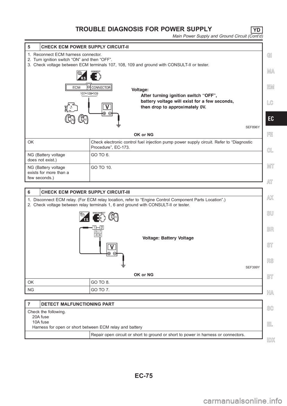
1. Reconnect ECM harness connector.
2. Turn ignition switch “ON” and then “OFF”.
3. Check voltage between ECM terminals 107, 108, 109 and ground with CONSULT-II or tester.
SEF896Y
OK or NG
OK Check electronic control fuel injection pump power supply circuit. Refer to “Diagnostic
Procedure”, EC-173.
NG (Battery voltage
does not exist.)GO TO 6.
NG (Battery voltage
exists for more than a
few seconds.)GO TO 10.
6 CHECK ECM POWER SUPPLY CIRCUIT-III
1. Disconnect ECM relay. (For ECM relay location, refer to “Engine ControlComponent Parts Location”.)
2. Check voltage between relay terminals 1, 6 and ground with CONSULT-II ortester.
SEF399Y
OK or NG
OK GO TO 8.
NG GO TO 7.
7 DETECT MALFUNCTIONING PART
Check the following.
20A fuse
10A fuse
Harness for open or short between ECM relay and battery
Repair open circuit or short to ground or short to power in harness or connectors.
GI
MA
EM
LC
FE
CL
MT
AT
AX
SU
BR
ST
RS
BT
HA
SC
EL
IDX
TROUBLE DIAGNOSIS FOR POWER SUPPLYYD
Main Power Supply and Ground Circuit (Cont’d)
EC-75