2003 NISSAN ALMERA N16 oil pressure
[x] Cancel search: oil pressurePage 2936 of 3189
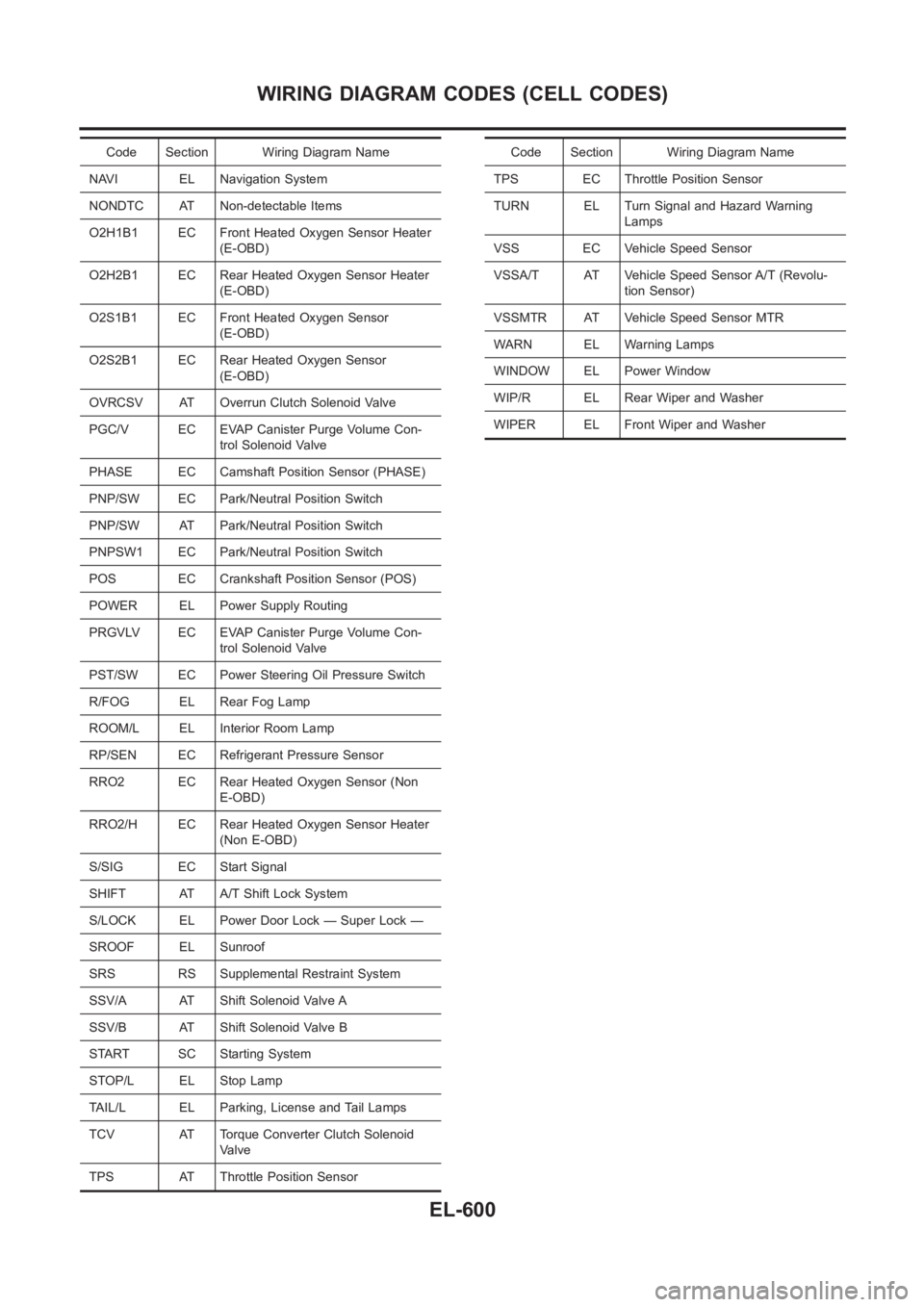
Code Section Wiring Diagram Name
NAVI EL Navigation System
NONDTC AT Non-detectable Items
O2H1B1 EC Front Heated Oxygen Sensor Heater
(E-OBD)
O2H2B1 EC Rear Heated Oxygen Sensor Heater
(E-OBD)
O2S1B1 EC Front Heated Oxygen Sensor
(E-OBD)
O2S2B1 EC Rear Heated Oxygen Sensor
(E-OBD)
OVRCSV AT Overrun Clutch Solenoid Valve
PGC/V EC EVAP Canister Purge Volume Con-
trol Solenoid Valve
PHASE EC Camshaft Position Sensor (PHASE)
PNP/SW EC Park/Neutral Position Switch
PNP/SW AT Park/Neutral Position Switch
PNPSW1 EC Park/Neutral Position Switch
POS EC Crankshaft Position Sensor (POS)
POWER EL Power Supply Routing
PRGVLV EC EVAP Canister Purge Volume Con-
trol Solenoid Valve
PST/SW EC Power Steering Oil Pressure Switch
R/FOG EL Rear Fog Lamp
ROOM/L EL Interior Room Lamp
RP/SEN EC Refrigerant Pressure Sensor
RRO2 EC Rear Heated Oxygen Sensor (Non
E-OBD)
RRO2/H EC Rear Heated Oxygen Sensor Heater
(Non E-OBD)
S/SIG EC Start Signal
SHIFT AT A/T Shift Lock System
S/LOCK EL Power Door Lock — Super Lock —
SROOF EL Sunroof
SRS RS Supplemental Restraint System
SSV/A AT Shift Solenoid Valve A
SSV/B AT Shift Solenoid Valve B
START SC Starting System
STOP/L EL Stop Lamp
TAIL/L EL Parking, License and Tail Lamps
TCV AT Torque Converter Clutch Solenoid
Valve
TPS AT Throttle Position SensorCode Section Wiring Diagram Name
TPS EC Throttle Position Sensor
TURN EL Turn Signal and Hazard Warning
Lamps
VSS EC Vehicle Speed Sensor
VSSA/T AT Vehicle Speed Sensor A/T (Revolu-
tion Sensor)
VSSMTR AT Vehicle Speed Sensor MTR
WARN EL Warning Lamps
WINDOW EL Power Window
WIP/R EL Rear Wiper and Washer
WIPER EL Front Wiper and Washer
WIRING DIAGRAM CODES (CELL CODES)
EL-600
Page 2942 of 3189
Precautions for Service EquipmentNJHA0117RECOVERY/RECYCLING EQUIPMENTNJHA0117S01Follow the manufacturer’s instructions for machine operation and
machine maintenance. Never introduce any refrigerant other than
that specified into the machine.
ELECTRONIC LEAK DETECTORNJHA0117S02Follow the manufacture’s instructions for tester operation and
tester maintenance.
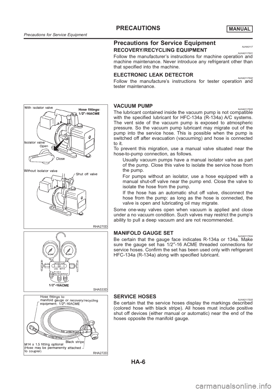
RHA270D
VACUUM PUMPNJHA0117S03The lubricant contained inside the vacuum pump is not compatible
with the specified lubricant for HFC-134a (R-134a) A/C systems.
The vent side of the vacuum pump is exposed to atmospheric
pressure. So the vacuum pump lubricant may migrate out of the
pump into the service hose. This is possible when the pump is
switched off after evacuation (vacuuming) and hose is connected
to it.
To prevent this migration, use a manual valve situated near the
hose-to-pump connection, as follows.
Usually vacuum pumps have a manual isolator valve as part
of the pump. Close this valve to isolate the service hose from
the pump.
For pumps without an isolator, use a hose equipped with a
manual shut-off valve near the pump end. Close the valve to
isolate the hose from the pump.
If the hose has an automatic shut off valve, disconnect the
hose from the pump: as long as the hose is connected, the
valve is open and lubricating oil may migrate.
Some one-way valves open when vacuum is applied and close
under a no vacuum condition. Such valves may restrict the pump’s
ability to pull a deep vacuum and are not recommended.
SHA533D
MANIFOLD GAUGE SETNJHA0117S04Be certain that the gauge face indicates R-134a or 134a. Make
sure the gauge set has 1/2″-16 ACME threaded connections for
service hoses. Confirm the set has been used only with refrigerant
HFC-134a (R-134a) along with specified lubricant.
RHA272D
SERVICE HOSESNJHA0117S05Be certain that the service hoses display the markings described
(colored hose with black stripe). All hoses must include positive
shut off devices (either manual or automatic) near the end of the
hoses opposite the manifold gauge.
PRECAUTIONSMANUAL
Precautions for Service Equipment
HA-6
Page 2948 of 3189
Refrigeration System
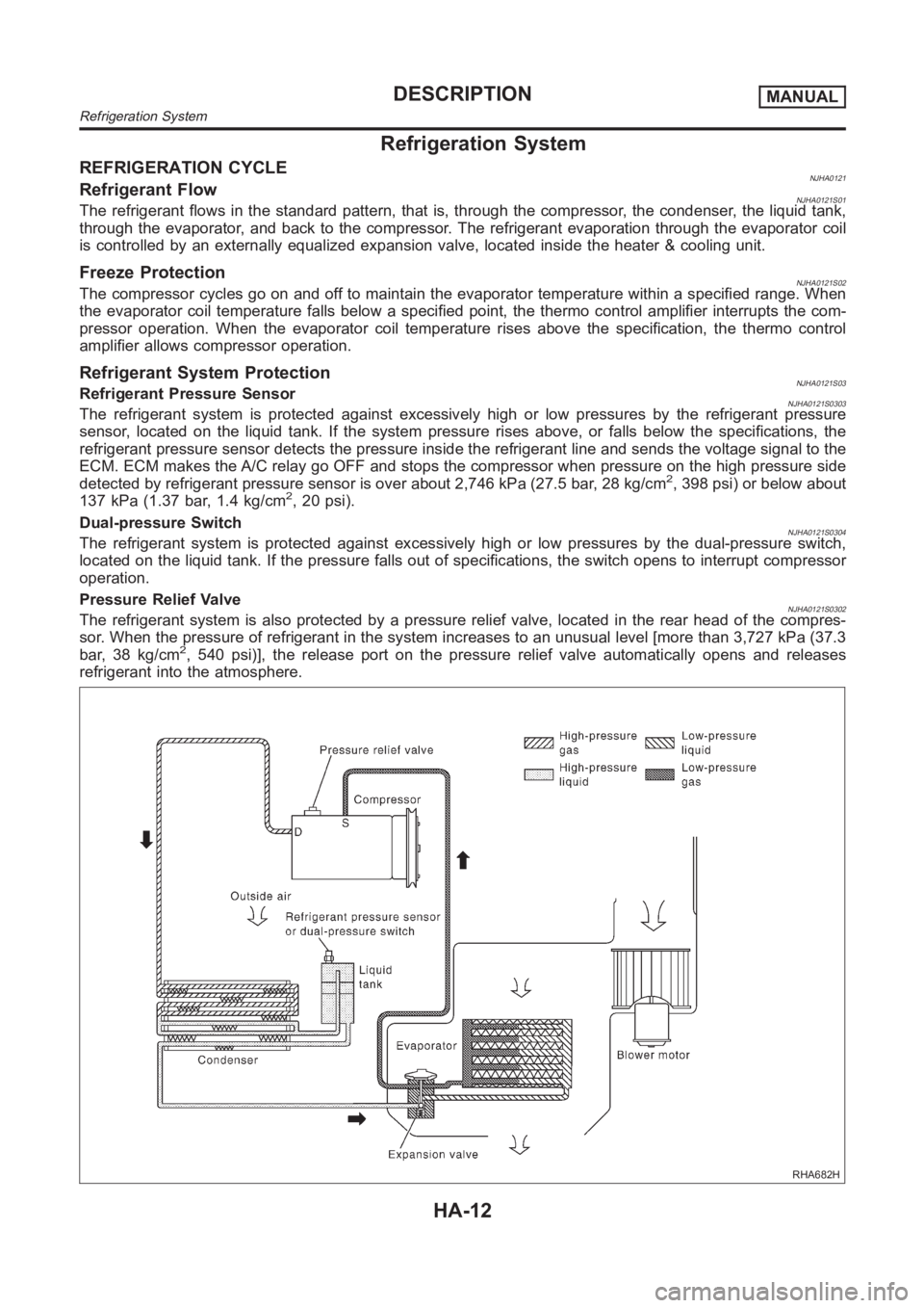
REFRIGERATION CYCLENJHA0121Refrigerant FlowNJHA0121S01The refrigerant flows in the standard pattern, that is, through the compressor, the condenser, the liquid tank,
through the evaporator, and back to the compressor. The refrigerant evaporation through the evaporator coil
is controlled by an externally equalized expansion valve, located insidethe heater & cooling unit.
Freeze ProtectionNJHA0121S02The compressor cycles go on and off to maintain the evaporator temperaturewithin a specified range. When
the evaporator coil temperature falls below a specified point, the thermocontrol amplifier interrupts the com-
pressor operation. When the evaporator coil temperature rises above the specification, the thermo control
amplifier allows compressor operation.
Refrigerant System ProtectionNJHA0121S03Refrigerant Pressure SensorNJHA0121S0303The refrigerant system is protected against excessively high or low pressures by the refrigerant pressure
sensor, located on the liquid tank. If the system pressure rises above, or falls below the specifications, the
refrigerant pressure sensor detects the pressure inside the refrigerantline and sends the voltage signal to the
ECM. ECM makes the A/C relay go OFF and stops the compressor when pressure onthe high pressure side
detected by refrigerant pressure sensor is over about 2,746 kPa (27.5 bar,28 kg/cm
2, 398 psi) or below about
137 kPa (1.37 bar, 1.4 kg/cm2, 20 psi).
Dual-pressure Switch
NJHA0121S0304The refrigerant system is protected against excessively high or low pressures by the dual-pressure switch,
located on the liquid tank. If the pressure falls out of specifications, the switch opens to interrupt compressor
operation.
Pressure Relief Valve
NJHA0121S0302The refrigerant system is also protected by a pressure relief valve, located in the rear head of the compres-
sor. When the pressure of refrigerant in the system increases to an unusuallevel [more than 3,727 kPa (37.3
bar, 38 kg/cm
2, 540 psi)], the release port on the pressure relief valve automatically opens and releases
refrigerant into the atmosphere.
RHA682H
DESCRIPTIONMANUAL
Refrigeration System
HA-12
Page 3144 of 3189
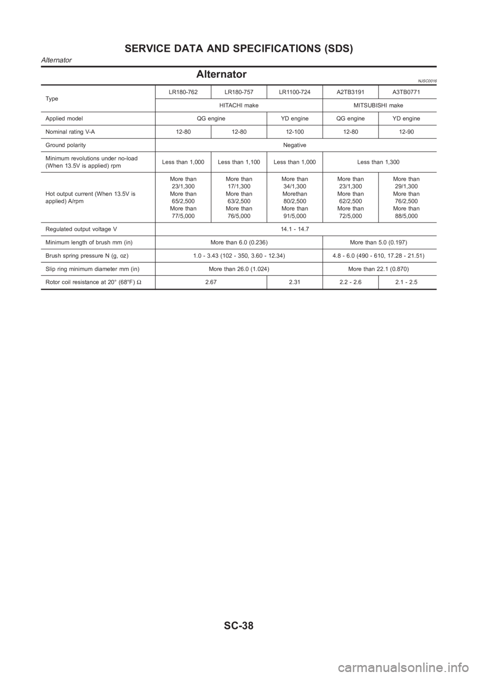
AlternatorNJSC0016
Ty p eLR180-762 LR180-757 LR1100-724 A2TB3191 A3TB0771
HITACHI make MITSUBISHI make
Applied model QG engine YD engine QG engine YD engine
Nominal rating V-A 12-80 12-80 12-100 12-80 12-90
Ground polarityNegative
Minimum revolutions under no-load
(When 13.5V is applied) rpmLess than 1,000 Less than 1,100 Less than 1,000 Less than 1,300
Hot output current (When 13.5V is
applied) A/rpmMore than
23/1,300
More than
65/2,500
More than
77/5,000More than
17/1,300
More than
63/2,500
More than
76/5,000More than
34/1,300
Morethan
80/2,500
More than
91/5,000More than
23/1,300
More than
62/2,500
More than
72/5,000More than
29/1,300
More than
76/2,500
More than
88/5,000
Regulated output voltage V 14.1 - 14.7
Minimum length of brush mm (in) More than 6.0 (0.236) More than 5.0 (0.197)
Brush spring pressure N (g, oz) 1.0 - 3.43 (102 - 350, 3.60 - 12.34) 4.8 - 6.0 (490 - 610, 17.28 - 21.51)
Slip ring minimum diameter mm (in) More than 26.0 (1.024) More than 22.1 (0.870)
Rotor coil resistance at 20° (68°F)Ω2.67 2.31 2.2 - 2.6 2.1 - 2.5
SERVICE DATA AND SPECIFICATIONS (SDS)
Alternator
SC-38
Page 3147 of 3189
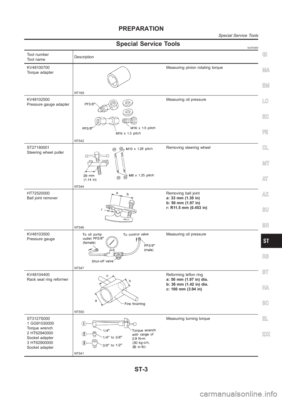
Special Service ToolsNJST0004
Tool number
Tool nameDescription
KV48100700
Torque adapter
NT169
Measuring pinion rotating torque
KV48102500
Pressure gauge adapter
NT542
Measuring oil pressure
ST27180001
Steering wheel puller
NT544
Removing steering wheel
HT72520000
Ball joint remover
NT546
Removing ball joint
a: 33 mm (1.30 in)
b: 50 mm (1.97 in)
r: R11.5 mm (0.453 in)
KV48103500
Pressure gauge
NT547
Measuring oil pressure
KV48104400
Rack seal ring reformer
NT550
Reforming teflon ring
a: 50 mm (1.97 in) dia.
b: 36 mm (1.42 in) dia.
c: 100 mm (3.94 in)
ST3127S000
1 GG91030000
Torque wrench
2 HT62940000
Socket adapter
3 HT62900000
Socket adapter
NT541
Measuring turning torque
GI
MA
EM
LC
EC
FE
CL
MT
AT
AX
SU
BR
RS
BT
HA
SC
EL
IDX
PREPARATION
Special Service Tools
ST-3
Page 3152 of 3189
Bleeding Hydraulic SystemNJST00141. Raise front end of vehicle until wheels are clear of the ground.
2. Add fluid into oil tank to specified level. Then quickly turn steer-
ing wheel fully to right and left and lightly touch steering stop-
pers.
Repeat steering wheel operation until fluid level no longer
decreases.
3. Start engine.
Repeat step 2. above.
Incomplete air bleeding will cause the following to occur. When
this happens, bleed air again.
a) Air bubbles in reservoir tank
b) Clicking noise in oil pump
c) Excessive buzzing in oil pump
Fluid noise may occur in the valve or oil pump. This is common
when the vehicle is stationary or while turning the steering wheel
slowly. This does not affect the performance or durability of the
system.
SST491B
SST090B
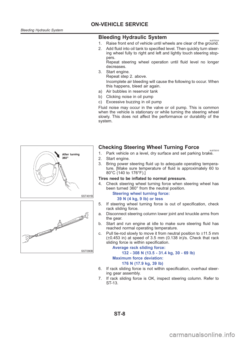
Checking Steering Wheel Turning ForceNJST00151. Park vehicle on a level, dry surface and set parking brake.
2. Start engine.
3. Bring power steering fluid up to adequate operating tempera-
ture. [Make sure temperature of fluid is approximately 60 to
80°C (140 to 176°F).]
Tires need to be inflated to normal pressure.
4. Check steering wheel turning force when steering wheel has
been turned 360° from the neutral position.
Steering wheel turning force:
39 N (4 kg, 9 lb) or less
5. If steering wheel turning force is out of specification, check
rack sliding force.
a. Disconnect steering column lower joint and knuckle arms from
the gear.
b. Start and run engine at idle to make sure steering fluid has
reached normal operating temperature.
c. Pull tie-rod slowly to move it from neutral position to±11 . 5 m m
(±0.453 in) at speed of 3.5 mm (0.138 in)/s. Check that rack
sliding force is within specification.
Average rack sliding force:
132 - 308 N (13.5 - 31.4 kg, 30 - 69 lb)
Maximum force deviation:
176 N (17.9 kg, 39 lb)
6. If rack sliding force is not within specification, overhaul steer-
ing gear assembly.
7. If rack sliding force is OK, inspect steering column. Refer to
ST-13.
ON-VEHICLE SERVICE
Bleeding Hydraulic System
ST-8
Page 3153 of 3189
SST834-I
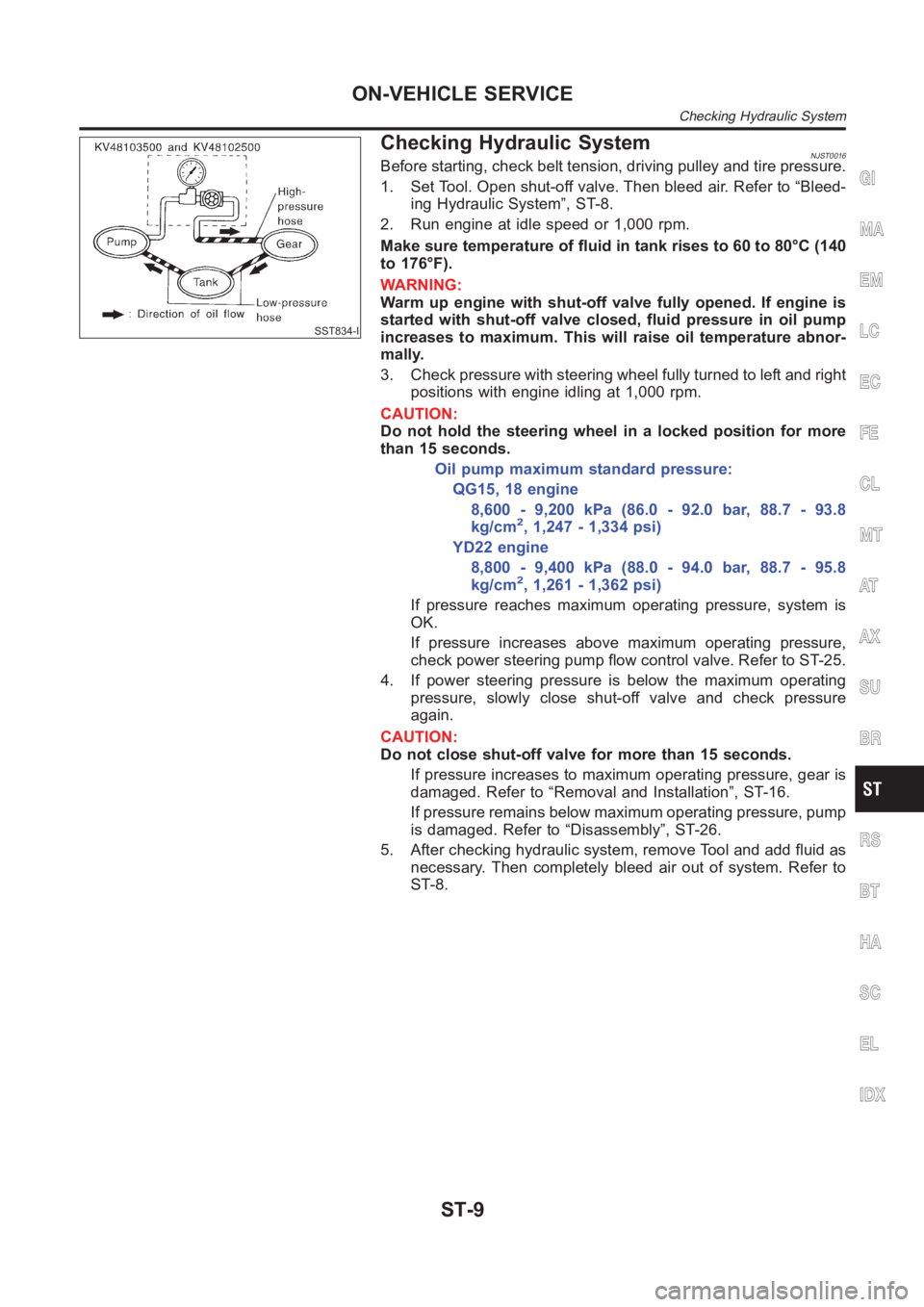
Checking Hydraulic SystemNJST0016Before starting, check belt tension, driving pulley and tire pressure.
1. Set Tool. Open shut-off valve. Then bleed air. Refer to “Bleed-
ing Hydraulic System”, ST-8.
2. Run engine at idle speed or 1,000 rpm.
Make sure temperature of fluid in tank rises to 60 to 80°C (140
to 176°F).
WARNING:
Warm up engine with shut-off valve fully opened. If engine is
started with shut-off valve closed, fluid pressure in oil pump
increases to maximum. This will raise oil temperature abnor-
mally.
3. Check pressure with steering wheel fully turned to left and right
positions with engine idling at 1,000 rpm.
CAUTION:
Do not hold the steering wheel in a locked position for more
than 15 seconds.
Oil pump maximum standard pressure:
QG15, 18 engine
8,600 - 9,200 kPa (86.0 - 92.0 bar, 88.7 - 93.8
kg/cm
2, 1,247 - 1,334 psi)
YD22 engine
8,800 - 9,400 kPa (88.0 - 94.0 bar, 88.7 - 95.8
kg/cm
2, 1,261 - 1,362 psi)
If pressure reaches maximum operating pressure, system is
OK.
If pressure increases above maximum operating pressure,
check power steering pump flow control valve. Refer to ST-25.
4. If power steering pressure is below the maximum operating
pressure, slowly close shut-off valve and check pressure
again.
CAUTION:
Do not close shut-off valve for more than 15 seconds.
If pressure increases to maximum operating pressure, gear is
damaged. Refer to “Removal and Installation”, ST-16.
If pressure remains below maximum operating pressure, pump
is damaged. Refer to “Disassembly”, ST-26.
5. After checking hydraulic system, remove Tool and add fluid as
necessary. Then completely bleed air out of system. Refer to
ST-8.
GI
MA
EM
LC
EC
FE
CL
MT
AT
AX
SU
BR
RS
BT
HA
SC
EL
IDX
ON-VEHICLE SERVICE
Checking Hydraulic System
ST-9
Page 3168 of 3189

Component DescriptionNJST0045The power steering pump can not be disassembled on QG engine
models.
Tightening torque:
Bracket bolt:
14 - 18 N·m
(1.36 - 1.84 kg-m, 10 - 13 ft-lb)
Lower fixing bolt:
32 - 42 N·m
(3.2 - 4.2 kg-m, 24 - 31 ft-lb)
Inspection:
Check oil pump maximum pressure. Refer to “Power
Steering” in SDS.
POWER STEERING OIL PUMP (QG ENGINE)
Component Description
ST-24