Page 1404 of 3189
SMT731D
11. Install selector, selector shaft, and selector shaft pin into clutch
housing.
SMT732D
12. Hammer the welch plug (selector shaft side) with a general-
purpose drift [OD: 12 mm (0.47 in)].
CAUTION:
Do not reuse welch plug.
SMT733DA
SMT734D
13. Install select check leaf spring, return spring, steel ball, reverse
gate, selector arm, bushing, and return bearing. Then, tighten
two reamer bolts with specified torque.
CAUTION:
Use correct reamer bolts for each installation point, because
each bolt has a different length.
SMT735D
14. Install oil pocket.
ASSEMBLYRS5F70A
Clutch Housing (Cont’d)
MT-84
Page 1405 of 3189
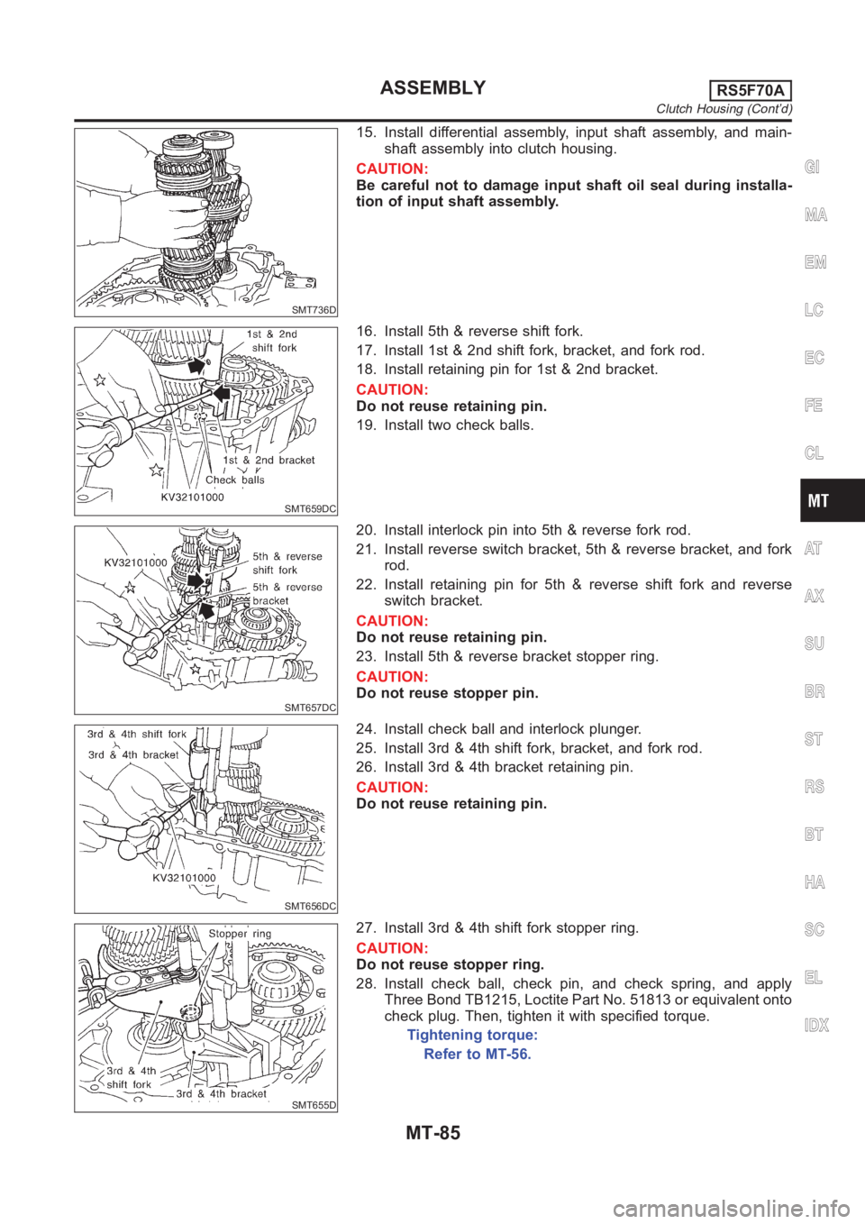
SMT736D
15. Install differential assembly, input shaft assembly, and main-
shaft assembly into clutch housing.
CAUTION:
Be careful not to damage input shaft oil seal during installa-
tion of input shaft assembly.
SMT659DC
16. Install 5th & reverse shift fork.
17. Install 1st & 2nd shift fork, bracket, and fork rod.
18. Install retaining pin for 1st & 2nd bracket.
CAUTION:
Do not reuse retaining pin.
19. Install two check balls.
SMT657DC
20. Install interlock pin into 5th & reverse fork rod.
21. Install reverse switch bracket, 5th & reverse bracket, and fork
rod.
22. Install retaining pin for 5th & reverse shift fork and reverse
switch bracket.
CAUTION:
Do not reuse retaining pin.
23. Install 5th & reverse bracket stopper ring.
CAUTION:
Do not reuse stopper pin.
SMT656DC
24. Install check ball and interlock plunger.
25. Install 3rd & 4th shift fork, bracket, and fork rod.
26. Install 3rd & 4th bracket retaining pin.
CAUTION:
Do not reuse retaining pin.
SMT655D
27. Install 3rd & 4th shift fork stopper ring.
CAUTION:
Do not reuse stopper ring.
28. Install check ball, check pin, and check spring, and apply
Three Bond TB1215, Loctite Part No. 51813 or equivalent onto
check plug. Then, tighten it with specified torque.
Tightening torque:
Refer to MT-56.
GI
MA
EM
LC
EC
FE
CL
AT
AX
SU
BR
ST
RS
BT
HA
SC
EL
IDX
ASSEMBLYRS5F70A
Clutch Housing (Cont’d)
MT-85
Page 1409 of 3189
SMT649D
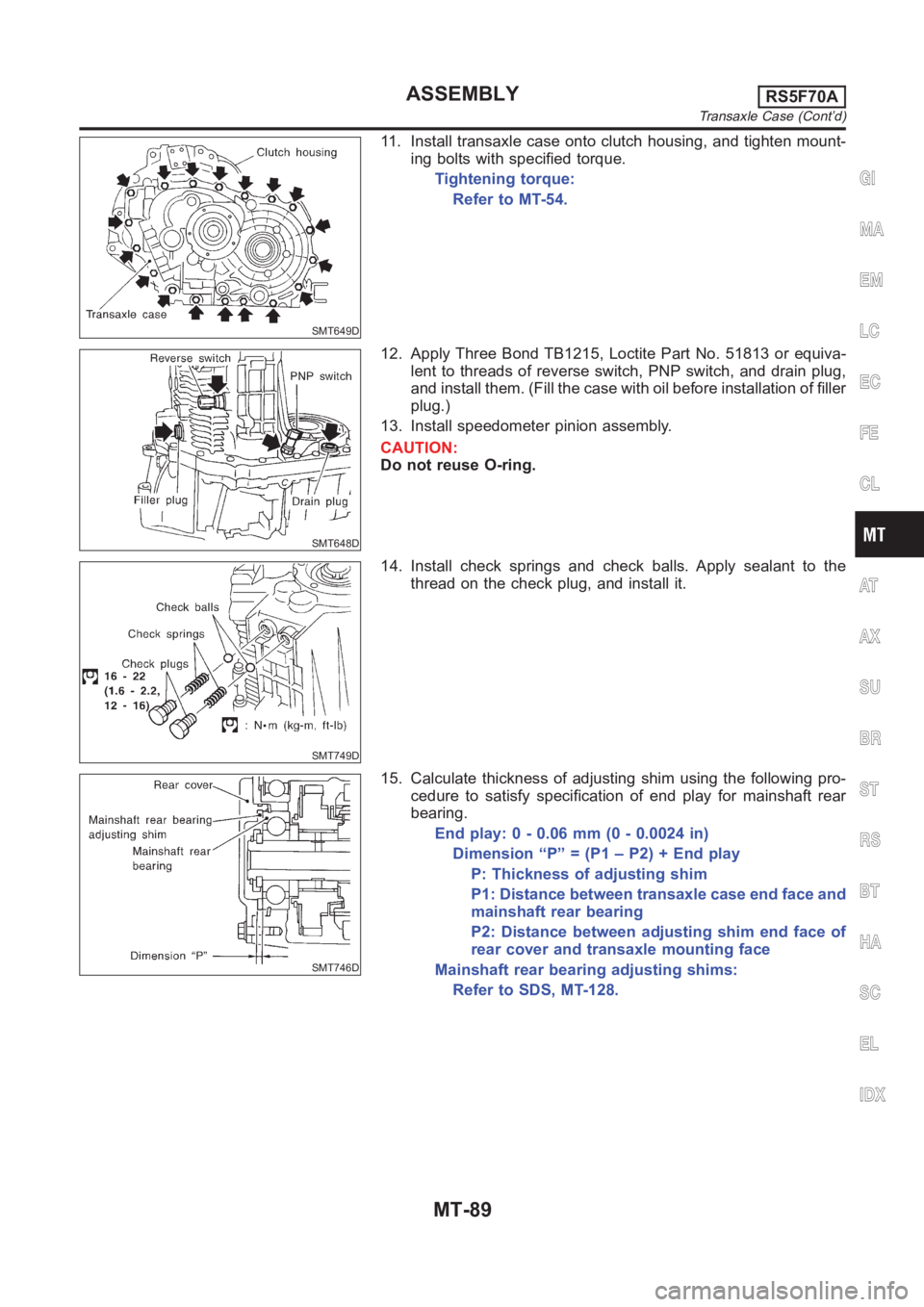
11. Install transaxle case onto clutch housing, and tighten mount-
ing bolts with specified torque.
Tightening torque:
Refer to MT-54.
SMT648D
12. Apply Three Bond TB1215, Loctite Part No. 51813 or equiva-
lent to threads of reverse switch, PNP switch, and drain plug,
and install them. (Fill the case with oil before installation of filler
plug.)
13. Install speedometer pinion assembly.
CAUTION:
Do not reuse O-ring.
SMT749D
14. Install check springs and check balls. Apply sealant to the
thread on the check plug, and install it.
SMT746D
15. Calculate thickness of adjusting shim using the following pro-
cedure to satisfy specification of end play for mainshaft rear
bearing.
End play: 0 - 0.06 mm (0 - 0.0024 in)
Dimension “P” = (P1 – P2) + End play
P: Thickness of adjusting shim
P1: Distance between transaxle case end face and
mainshaft rear bearing
P2: Distance between adjusting shim end face of
rear cover and transaxle mounting face
Mainshaft rear bearing adjusting shims:
Refer to SDS, MT-128.
GI
MA
EM
LC
EC
FE
CL
AT
AX
SU
BR
ST
RS
BT
HA
SC
EL
IDX
ASSEMBLYRS5F70A
Transaxle Case (Cont’d)
MT-89
Page 1410 of 3189
SMT747D
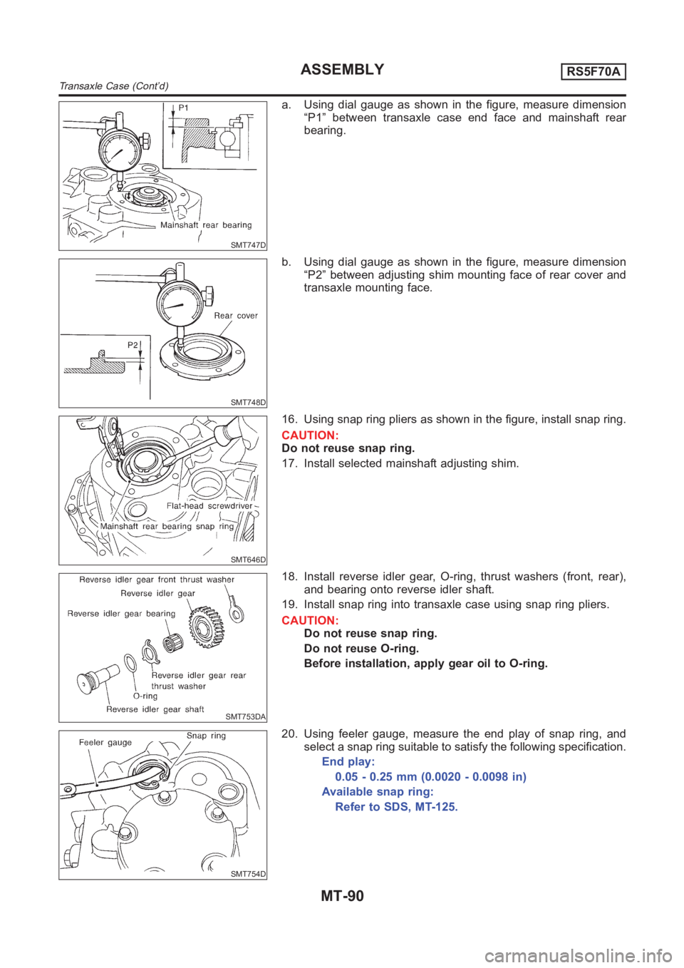
a. Using dial gauge as shown in the figure, measure dimension
“P1” between transaxle case end face and mainshaft rear
bearing.
SMT748D
b. Using dial gauge as shown in the figure, measure dimension
“P2” between adjusting shim mounting face of rear cover and
transaxle mounting face.
SMT646D
16. Using snap ring pliers as shown in the figure, install snap ring.
CAUTION:
Do not reuse snap ring.
17. Install selected mainshaft adjusting shim.
SMT753DA
18. Install reverse idler gear, O-ring, thrust washers (front, rear),
and bearing onto reverse idler shaft.
19. Install snap ring into transaxle case using snap ring pliers.
CAUTION:
Do not reuse snap ring.
Do not reuse O-ring.
Before installation, apply gear oil to O-ring.
SMT754D
20. Using feeler gauge, measure the end play of snap ring, and
select a snap ring suitable to satisfy the following specification.
End play:
0.05 - 0.25 mm (0.0020 - 0.0098 in)
Available snap ring:
Refer to SDS, MT-125.
ASSEMBLYRS5F70A
Transaxle Case (Cont’d)
MT-90
Page 1413 of 3189
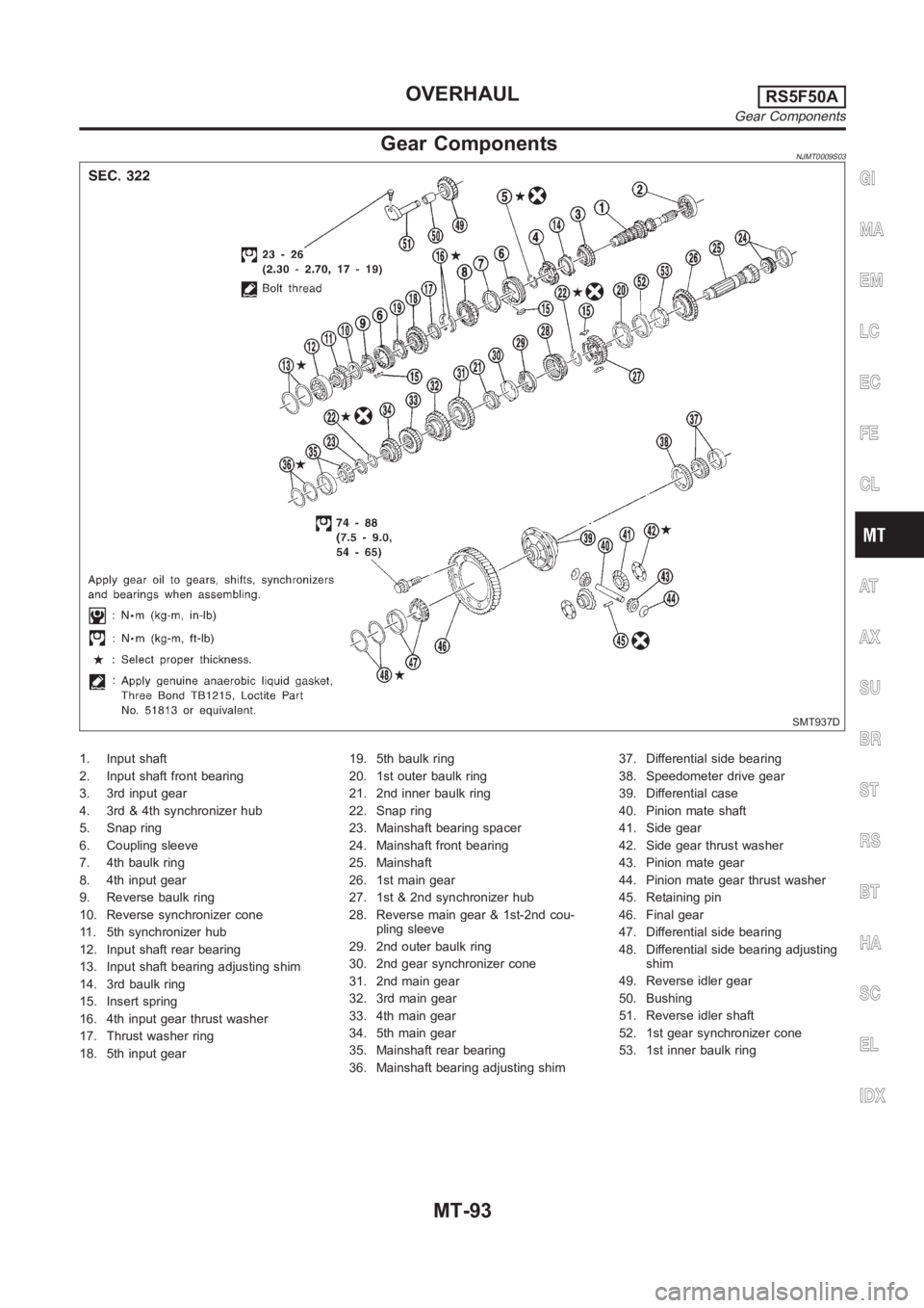
Gear ComponentsNJMT0009S03
SMT937D
1. Input shaft
2. Input shaft front bearing
3. 3rd input gear
4. 3rd & 4th synchronizer hub
5. Snap ring
6. Coupling sleeve
7. 4th baulk ring
8. 4th input gear
9. Reverse baulk ring
10. Reverse synchronizer cone
11. 5th synchronizer hub
12. Input shaft rear bearing
13. Input shaft bearing adjusting shim
14. 3rd baulk ring
15. Insert spring
16. 4th input gear thrust washer
17. Thrust washer ring
18. 5th input gear19. 5th baulk ring
20. 1st outer baulk ring
21. 2nd inner baulk ring
22. Snap ring
23. Mainshaft bearing spacer
24. Mainshaft front bearing
25. Mainshaft
26. 1st main gear
27. 1st & 2nd synchronizer hub
28. Reverse main gear & 1st-2nd cou-
pling sleeve
29. 2nd outer baulk ring
30. 2nd gear synchronizer cone
31. 2nd main gear
32. 3rd main gear
33. 4th main gear
34. 5th main gear
35. Mainshaft rear bearing
36. Mainshaft bearing adjusting shim37. Differential side bearing
38. Speedometer drive gear
39. Differential case
40. Pinion mate shaft
41. Side gear
42. Side gear thrust washer
43. Pinion mate gear
44. Pinion mate gear thrust washer
45. Retaining pin
46. Final gear
47. Differential side bearing
48. Differential side bearing adjusting
shim
49. Reverse idler gear
50. Bushing
51. Reverse idler shaft
52. 1st gear synchronizer cone
53. 1st inner baulk ring
GI
MA
EM
LC
EC
FE
CL
AT
AX
SU
BR
ST
RS
BT
HA
SC
EL
IDX
OVERHAULRS5F50A
Gear Components
MT-93
Page 1414 of 3189
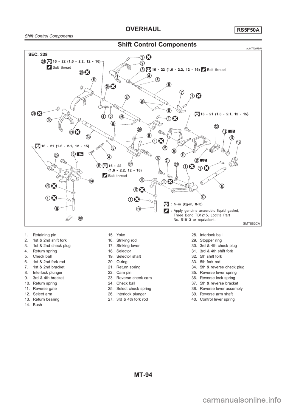
Shift Control ComponentsNJMT0009S04
SMT862CA
1. Retaining pin
2. 1st & 2nd shift fork
3. 1st & 2nd check plug
4. Return spring
5. Check ball
6. 1st & 2nd fork rod
7. 1st & 2nd bracket
8. Interlock plunger
9. 3rd & 4th bracket
10. Return spring
11. Reverse gate
12. Select arm
13. Return bearing
14. Bush15. Yoke
16. Striking rod
17. Striking lever
18. Selector
19. Selector shaft
20. O-ring
21. Return spring
22. Cam pin
23. Reverse check cam
24. Check ball
25. Select check spring
26. Interlock plunger
27. 3rd & 4th fork rod28. Interlock ball
29. Stopper ring
30. 3rd & 4th check plug
31. 3rd & 4th shift fork
32. 5th shift fork
33. 5th fork rod
34. 5th & reverse check plug
35. Reverse lever spring
36. Reverse lock spring
37. 5th & reverse bracket
38. Reverse lever assembly
39. Reverse arm shaft
40. Control lever spring
OVERHAULRS5F50A
Shift Control Components
MT-94
Page 1415 of 3189
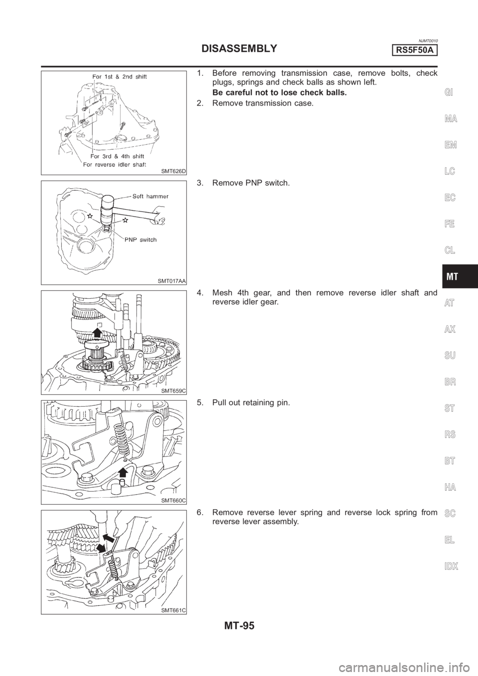
NJMT0010
SMT626D
1. Before removing transmission case, remove bolts, check
plugs, springs and check balls as shown left.
Be careful not to lose check balls.
2. Remove transmission case.
SMT017AA
3. Remove PNP switch.
SMT659C
4. Mesh 4th gear, and then remove reverse idler shaft and
reverse idler gear.
SMT660C
5. Pull out retaining pin.
SMT661C
6. Remove reverse lever spring and reverse lock spring from
reverse lever assembly.
GI
MA
EM
LC
EC
FE
CL
AT
AX
SU
BR
ST
RS
BT
HA
SC
EL
IDX
DISASSEMBLYRS5F50A
MT-95
Page 1416 of 3189
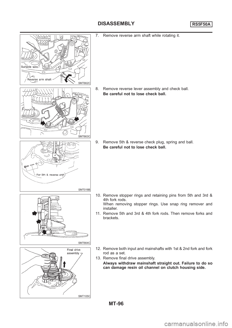
SMT662C
7. Remove reverse arm shaft while rotating it.
SMT663C
8. Remove reverse lever assembly and check ball.
Be careful not to lose check ball.
SMT018B
9. Remove 5th & reverse check plug, spring and ball.
Be careful not to lose check ball.
SMT664C
10. Remove stopper rings and retaining pins from 5th and 3rd &
4th fork rods.
When removing stopper rings. Use snap ring remover and
installer.
11. Remove 5th and 3rd & 4th fork rods. Then remove forks and
brackets.
SMT105C
12. Remove both input and mainshafts with 1st & 2nd fork and fork
rod as a set.
13. Remove final drive assembly.
Always withdraw mainshaft straight out. Failure to do so
can damage resin oil channel on clutch housing side.
DISASSEMBLYRS5F50A
MT-96
![NISSAN ALMERA N16 2003 Electronic Repair Manual SMT731D
11. Install selector, selector shaft, and selector shaft pin into clutch
housing.
SMT732D
12. Hammer the welch plug (selector shaft side) with a general-
purpose drift [OD: 12 mm (0.47 in)].
C](/manual-img/5/57350/w960_57350-1403.png "NISSAN ALMERA N16 2003 Electronic Repair Manual SMT731D
11. Install selector, selector shaft, and selector shaft pin into clutch
housing.
SMT732D
12. Hammer the welch plug (selector shaft side) with a general-
purpose drift [OD: 12 mm (0.47 in)].
C")