Page 1271 of 3189
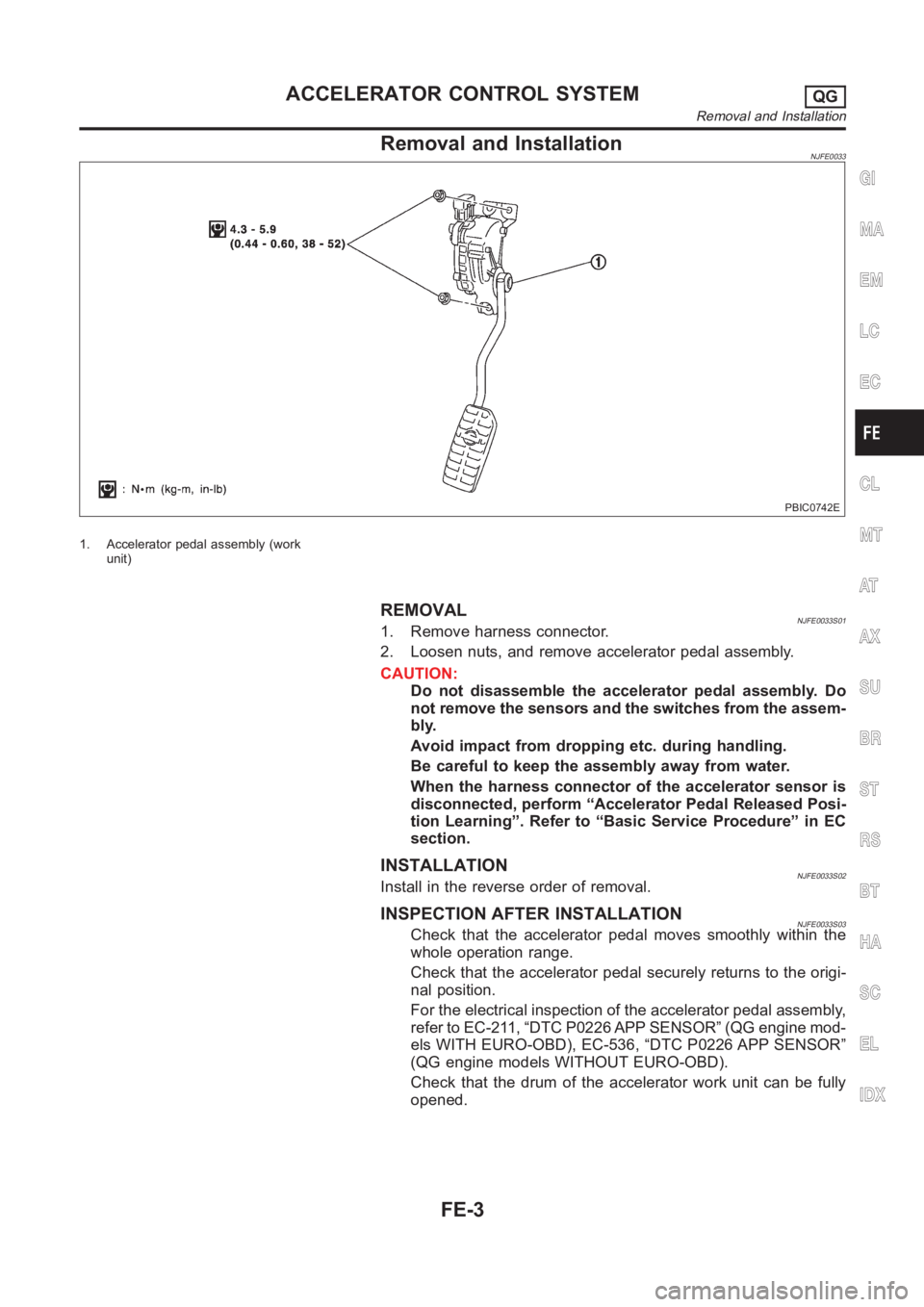
Removal and InstallationNJFE0033
PBIC0742E
1. Accelerator pedal assembly (work
unit)
REMOVALNJFE0033S011. Remove harness connector.
2. Loosen nuts, and remove accelerator pedal assembly.
CAUTION:
Do not disassemble the accelerator pedal assembly. Do
not remove the sensors and the switches from the assem-
bly.
Avoid impact from dropping etc. during handling.
Be careful to keep the assembly away from water.
When the harness connector of the accelerator sensor is
disconnected, perform “Accelerator Pedal Released Posi-
tion Learning”. Refer to “Basic Service Procedure” in EC
section.
INSTALLATIONNJFE0033S02Install in the reverse order of removal.
INSPECTION AFTER INSTALLATIONNJFE0033S03Check that the accelerator pedal moves smoothly within the
whole operation range.
Check that the accelerator pedal securely returns to the origi-
nal position.
For the electrical inspection of the accelerator pedal assembly,
refer to EC-211, “DTC P0226 APP SENSOR” (QG engine mod-
els WITH EURO-OBD), EC-536, “DTC P0226 APP SENSOR”
(QG engine models WITHOUT EURO-OBD).
Check that the drum of the accelerator work unit can be fully
opened.
GI
MA
EM
LC
EC
CL
MT
AT
AX
SU
BR
ST
RS
BT
HA
SC
EL
IDX
ACCELERATOR CONTROL SYSTEMQG
Removal and Installation
FE-3
Page 1275 of 3189
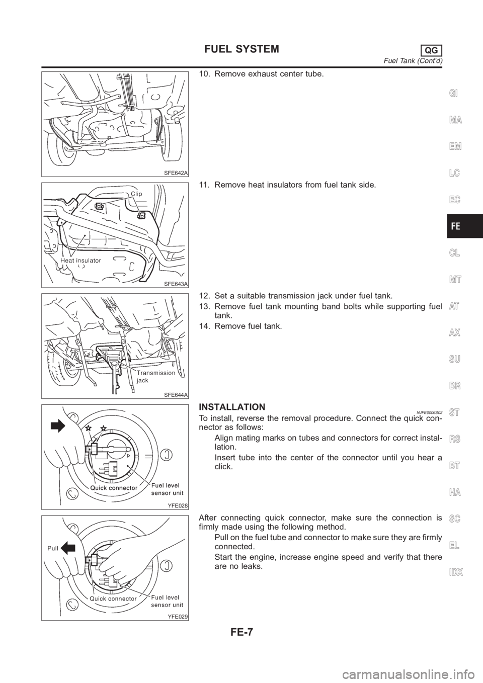
SFE642A
10. Remove exhaust center tube.
SFE643A
11. Remove heat insulators from fuel tank side.
SFE644A
12. Set a suitable transmission jack under fuel tank.
13. Remove fuel tank mounting band bolts while supporting fuel
tank.
14. Remove fuel tank.
YFE028
INSTALLATIONNJFE0006S02To install, reverse the removal procedure. Connect the quick con-
nector as follows:
Align mating marks on tubes and connectors for correct instal-
lation.
Insert tube into the center of the connector until you hear a
click.
YFE029
After connecting quick connector, make sure the connection is
firmly made using the following method.
Pull on the fuel tube and connector to make sure they are firmly
connected.
Start the engine, increase engine speed and verify that there
are no leaks.
GI
MA
EM
LC
EC
CL
MT
AT
AX
SU
BR
ST
RS
BT
HA
SC
EL
IDX
FUEL SYSTEMQG
Fuel Tank (Cont’d)
FE-7
Page 1277 of 3189
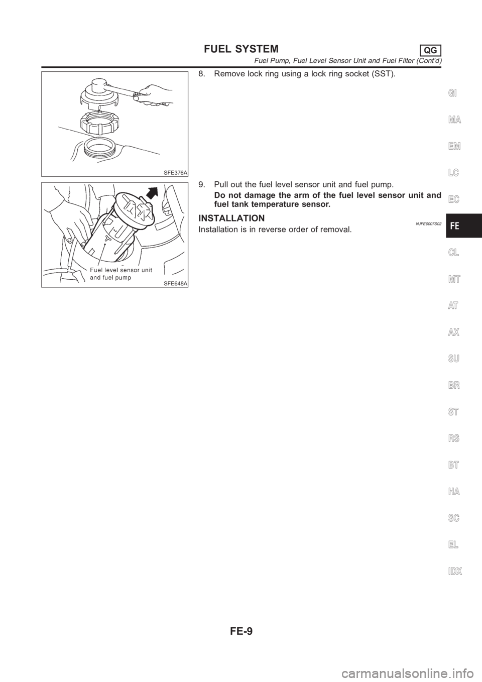
SFE376A
8. Remove lock ring using a lock ring socket (SST).
SFE648A
9. Pull out the fuel level sensor unit and fuel pump.
Do not damage the arm of the fuel level sensor unit and
fuel tank temperature sensor.
INSTALLATIONNJFE0007S02Installation is in reverse order of removal.
GI
MA
EM
LC
EC
CL
MT
AT
AX
SU
BR
ST
RS
BT
HA
SC
EL
IDX
FUEL SYSTEMQG
Fuel Pump, Fuel Level Sensor Unit and Fuel Filter (Cont’d)
FE-9
Page 1283 of 3189
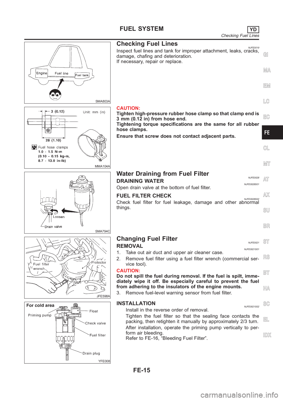
SMA803A
Checking Fuel LinesNJFE0019Inspect fuel lines and tank for improper attachment, leaks, cracks,
damage, chafing and deterioration.
If necessary, repair or replace.
MMA104A
CAUTION:
Tighten high-pressure rubber hose clamp so that clamp end is
3 mm (0.12 in) from hose end.
Tightening torque specifications are the same for all rubber
hose clamps.
Ensure that screw does not contact adjacent parts.
SMA794C
Water Draining from Fuel FilterNJFE0028DRAINING WATERNJFE0028S01Open drain valve at the bottom of fuel filter.
FUEL FILTER CHECKNJFE0028S02Check fuel filter for fuel leakage, damage and other abnormal
things.
JFE598A
Changing Fuel FilterNJFE0021REMOVALNJFE0021S011. Take out air duct and upper air cleaner case.
2. Remove fuel filter using a fuel filter wrench (commercial ser-
vice tool).
CAUTION:
Do not spill the fuel during removal. If the fuel is spilt, imme-
diately wipe it off. Be especially careful to prevent the fuel
from adhering to the insulators of the engine mounts.
3. Remove fuel-level warning sensor from fuel filter.
YFE008
INSTALLATIONNJFE0021S02Install in the reverse order of removal.
Tighten the fuel filter so that the sealing face contacts the
packing, then retighten it manually by approximately 2/3 turn.
After installation, operate the priming pump vertically to per-
form air bleeding.
Refer to FE-16, “Bleeding Fuel Filter”.
GI
MA
EM
LC
EC
CL
MT
AT
AX
SU
BR
ST
RS
BT
HA
SC
EL
IDX
FUEL SYSTEMYD
Checking Fuel Lines
FE-15
Page 1290 of 3189
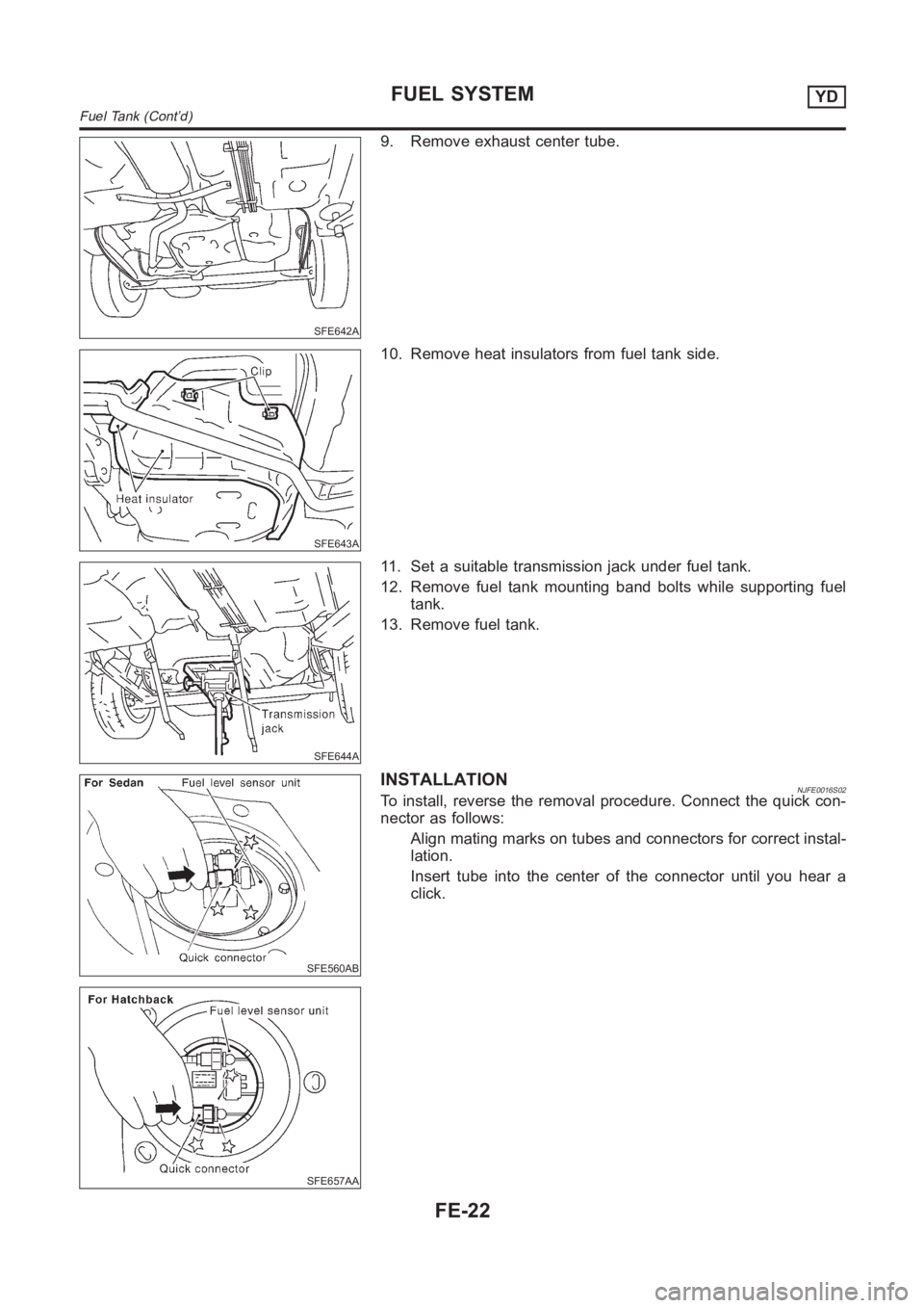
SFE642A
9. Remove exhaust center tube.
SFE643A
10. Remove heat insulators from fuel tank side.
SFE644A
11. Set a suitable transmission jack under fuel tank.
12. Remove fuel tank mounting band bolts while supporting fuel
tank.
13. Remove fuel tank.
SFE560AB
SFE657AA
INSTALLATIONNJFE0016S02To install, reverse the removal procedure. Connect the quick con-
nector as follows:
Align mating marks on tubes and connectors for correct instal-
lation.
Insert tube into the center of the connector until you hear a
click.
FUEL SYSTEMYD
Fuel Tank (Cont’d)
FE-22
Page 1293 of 3189
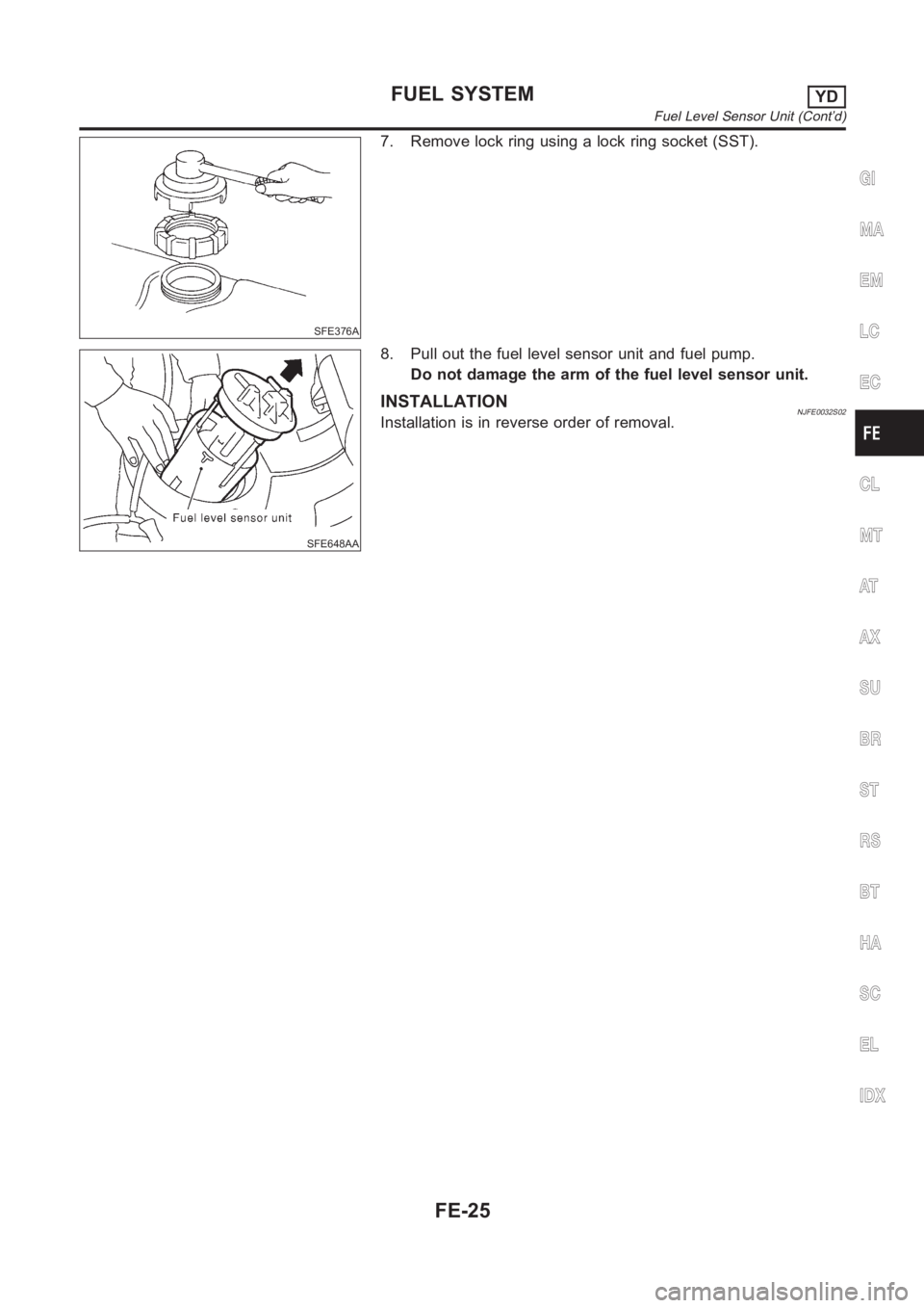
SFE376A
7. Remove lock ring using a lock ring socket (SST).
SFE648AA
8. Pull out the fuel level sensor unit and fuel pump.
Do not damage the arm of the fuel level sensor unit.
INSTALLATIONNJFE0032S02Installation is in reverse order of removal.
GI
MA
EM
LC
EC
CL
MT
AT
AX
SU
BR
ST
RS
BT
HA
SC
EL
IDX
FUEL SYSTEMYD
Fuel Level Sensor Unit (Cont’d)
FE-25
Page 1311 of 3189
AssemblyNJCL00231. Apply recommended rubber grease to piston cup and piston,
and insert piston assembly.
2. Install dust cover.
InstallationNJCL0024Install the components in the reverse order of removal. Adhere to
the operations described below.
CAUTION:
Install the hose without twisting it.
The copper washer of the union bolt should not be reused.
Always use a new copper washer for installation.
After finishing the operation, bleed air from the clutch
piping connector and operating cylinder. Refer to “Air
Bleeding Procedure”, CL-10.
GI
MA
EM
LC
EC
FE
MT
AT
AX
SU
BR
ST
RS
BT
HA
SC
EL
IDX
OPERATING CYLINDER
Assembly
CL-15
Page 1317 of 3189
Clean old grease and abrasive materials off the grease
application area.
SCL815
NOTE:
Equally apply a coat [approximately 1 mm (0.04 in) thick] of
clutch sleeve grease to withdrawal lever and holder spring
frictional surfaces.
Apply a coat of clutch sleeve grease to the grooves on contact
surfaces of the withdrawal lever ball pin and inner surface of
release bearing so that grease application, make sure that
grease is flush with grooves.
Equally apply a thin coat of clutch sleeve grease to release
bearing frictional surface. After grease application, install
release bearing. Wipe off excess grease forced out during
bearing installation. Remove release bearing.
2. Installation is in the reverse order of removal.
GI
MA
EM
LC
EC
FE
MT
AT
AX
SU
BR
ST
RS
BT
HA
SC
EL
IDX
CLUTCH RELEASE MECHANISMRS5F50A
Installation (Cont’d)
CL-21
![NISSAN ALMERA N16 2003 Electronic Repair Manual Clean old grease and abrasive materials off the grease
application area.
SCL815
NOTE:
Equally apply a coat [approximately 1 mm (0.04 in) thick] of
clutch sleeve grease to withdrawal lever and holder s](/manual-img/5/57350/w960_57350-1316.png "NISSAN ALMERA N16 2003 Electronic Repair Manual Clean old grease and abrasive materials off the grease
application area.
SCL815
NOTE:
Equally apply a coat [approximately 1 mm (0.04 in) thick] of
clutch sleeve grease to withdrawal lever and holder s")