Page 157 of 3189
![NISSAN ALMERA N16 2003 Electronic Repair Manual CYLINDER BLOCK
EM-79
[QG]
C
D
E
F
G
H
I
J
K
L
MA
EM
18. Install flywheel or drive plate.
●Install drive plate in direction shown in figure.
●Fix crankshaft with ring gear stopper (special service](/manual-img/5/57350/w960_57350-156.png "NISSAN ALMERA N16 2003 Electronic Repair Manual CYLINDER BLOCK
EM-79
[QG]
C
D
E
F
G
H
I
J
K
L
MA
EM
18. Install flywheel or drive plate.
●Install drive plate in direction shown in figure.
●Fix crankshaft with ring gear stopper (special service")
CYLINDER BLOCK
EM-79
[QG]
C
D
E
F
G
H
I
J
K
L
MA
EM
18. Install flywheel or drive plate.
●Install drive plate in direction shown in figure.
●Fix crankshaft with ring gear stopper (special service tool).
●Tighten mounting bolts diagonally in several steps.
19. Install oil level gauge guide.
●Press it in with punch mark for installing instruction in direction
shown in figure.
●Apply locking agent to pressed position.
20. Install knock sensor.
●Install sensor with connector facing lower right by 45° as
shown.
CAUTION:
●If any impact by dropping is applied to the knock sensor,
replace it with new one.
●Make sure that there is no foreign material on the cylin-
der block mating surface and the back surface of the
knock sensor.
●Do not tighten the mounting bolts while holding the con-
nector.
●Make sure that the knock sensor does not interfere with other parts.
21. Install crankshaft position sensor (POS).
●Tighten bolt after fully inserting crankshaft position sensor (POS) into cylinder block.
22. Tighten accessory brackets to the following tightening torque.
23. Assemble in the reverse order of disassembly.
PBIC0595E
PBIC0596E
Power steering pump bracket:
: 16.7 - 23.5 N·m (1.7 - 2.4 kg-m, 13 - 17 ft-lb)
Alternator air conditioner compressor bracket:
: 33.3 - 46.1 N·m (3.4 - 4.7 kg-m, 25 - 34 ft-lb)
PBIC0597E
Page 197 of 3189
InstallationNJEM00911. Install each belt on pulley in reverse order of removal.
2. Adjust belt tension. Refer to EM-11, “Adjustment”.
3. Tighten nuts and bolts provided for adjustment to the specified
torque.
4. Check again that each belt tension is as specified.GI
MA
LC
EC
FE
CL
MT
AT
AX
SU
BR
ST
RS
BT
HA
SC
EL
IDX
DRIVE BELTSYD
Installation
EM-13
Page 200 of 3189
JEM114G
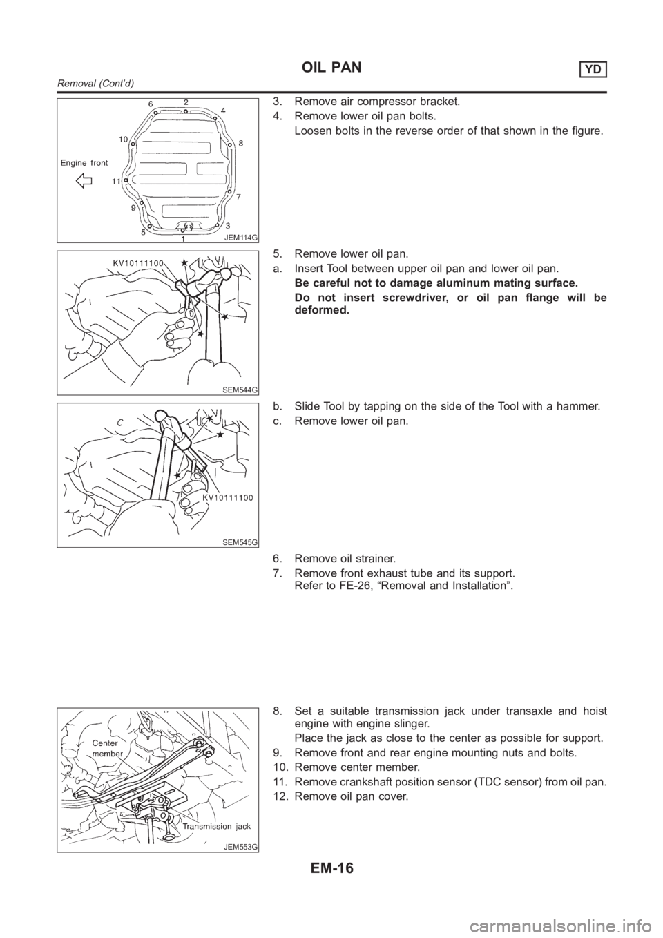
3. Remove air compressor bracket.
4. Remove lower oil pan bolts.
Loosen bolts in the reverse order of that shown in the figure.
SEM544G
5. Remove lower oil pan.
a. Insert Tool between upper oil pan and lower oil pan.
Be careful not to damage aluminum mating surface.
Do not insert screwdriver, or oil pan flange will be
deformed.
SEM545G
b. Slide Tool by tapping on the side of the Tool with a hammer.
c. Remove lower oil pan.
6. Remove oil strainer.
7. Remove front exhaust tube and its support.
Refer to FE-26, “Removal and Installation”.
JEM553G
8. Set a suitable transmission jack under transaxle and hoist
engine with engine slinger.
Place the jack as close to the center as possible for support.
9. Remove front and rear engine mounting nuts and bolts.
10. Remove center member.
11. Remove crankshaft position sensor (TDC sensor) from oil pan.
12. Remove oil pan cover.
OIL PANYD
Removal (Cont’d)
EM-16
Page 201 of 3189
JEM116G
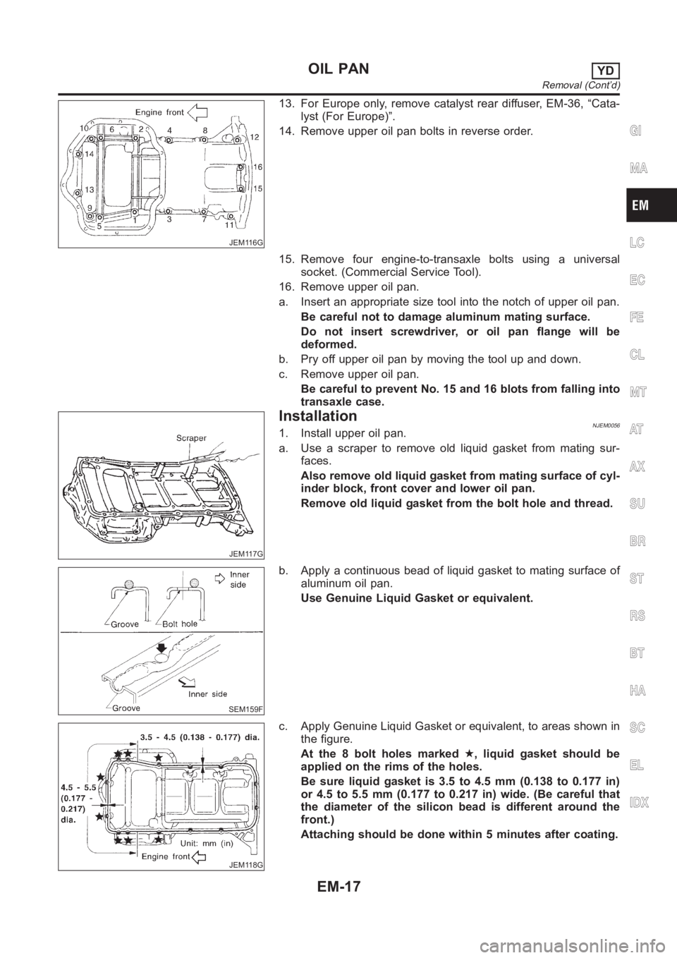
13. For Europe only, remove catalyst rear diffuser, EM-36, “Cata-
lyst (For Europe)”.
14. Remove upper oil pan bolts in reverse order.
15. Remove four engine-to-transaxle bolts using a universal
socket. (Commercial Service Tool).
16. Remove upper oil pan.
a. Insert an appropriate size tool into the notch of upper oil pan.
Be careful not to damage aluminum mating surface.
Do not insert screwdriver, or oil pan flange will be
deformed.
b. Pry off upper oil pan by moving the tool up and down.
c. Remove upper oil pan.
Be careful to prevent No. 15 and 16 blots from falling into
transaxle case.
JEM117G
InstallationNJEM00561. Install upper oil pan.
a. Use a scraper to remove old liquid gasket from mating sur-
faces.
Also remove old liquid gasket from mating surface of cyl-
inder block, front cover and lower oil pan.
Remove old liquid gasket from the bolt hole and thread.
SEM159F
b. Apply a continuous bead of liquid gasket to mating surface of
aluminum oil pan.
Use Genuine Liquid Gasket or equivalent.
JEM118G
c. Apply Genuine Liquid Gasket or equivalent, to areas shown in
the figure.
At the 8 bolt holes marked★, liquid gasket should be
applied on the rims of the holes.
Be sure liquid gasket is 3.5 to 4.5 mm (0.138 to 0.177 in)
or 4.5 to 5.5 mm (0.177 to 0.217 in) wide. (Be careful that
the diameter of the silicon bead is different around the
front.)
Attaching should be done within 5 minutes after coating.
GI
MA
LC
EC
FE
CL
MT
AT
AX
SU
BR
ST
RS
BT
HA
SC
EL
IDX
OIL PANYD
Removal (Cont’d)
EM-17
Page 205 of 3189
JEM121G
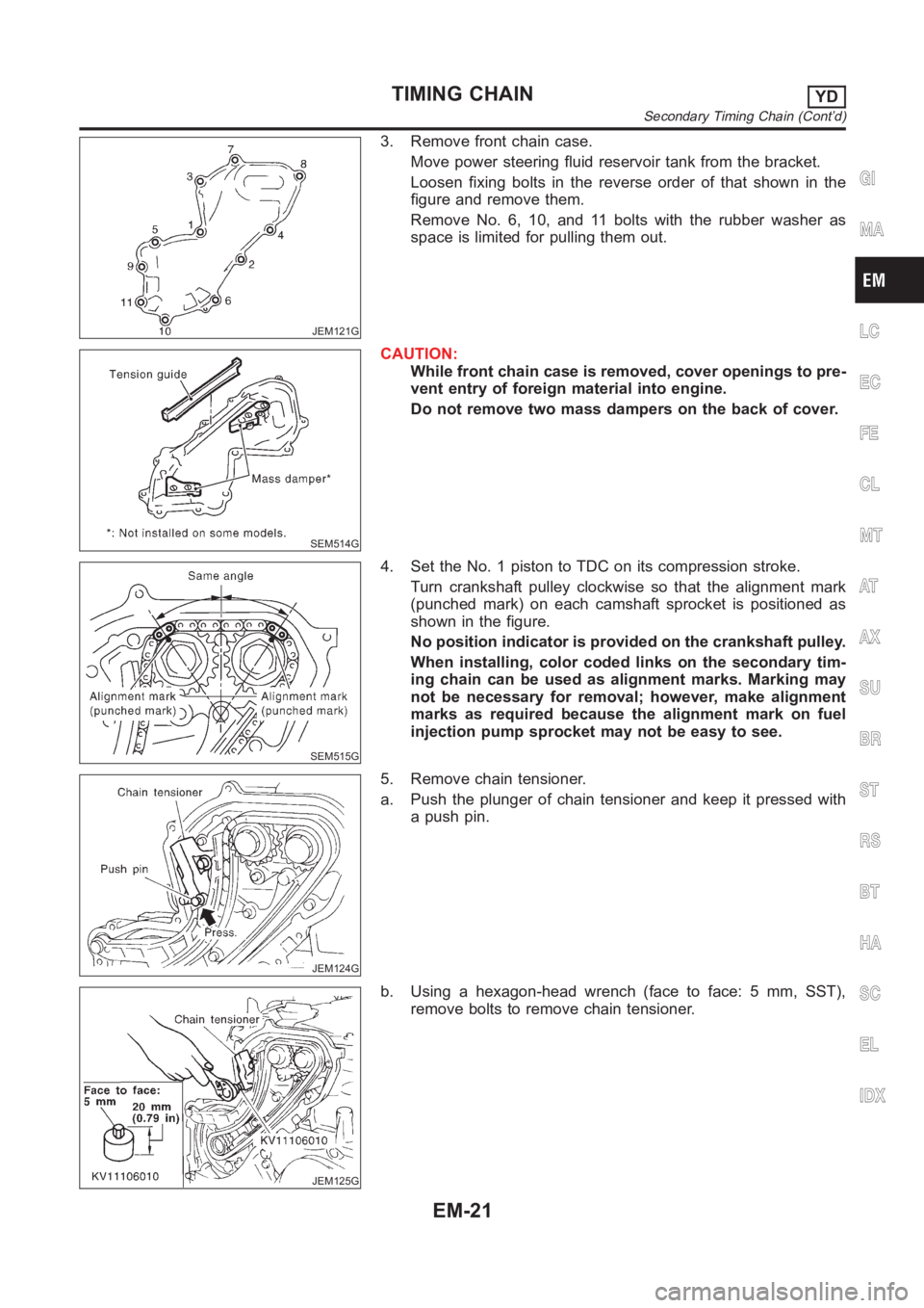
3. Remove front chain case.
Move power steering fluid reservoir tank from the bracket.
Loosen fixing bolts in the reverse order of that shown in the
figure and remove them.
Remove No. 6, 10, and 11 bolts with the rubber washer as
space is limited for pulling them out.
SEM514G
CAUTION:
While front chain case is removed, cover openings to pre-
vent entry of foreign material into engine.
Do not remove two mass dampers on the back of cover.
SEM515G
4. Set the No. 1 piston to TDC on its compression stroke.
Turn crankshaft pulley clockwise so that the alignment mark
(punched mark) on each camshaft sprocket is positioned as
shown in the figure.
No position indicator is provided on the crankshaft pulley.
When installing, color coded links on the secondary tim-
ing chain can be used as alignment marks. Marking may
not be necessary for removal; however, make alignment
marks as required because the alignment mark on fuel
injection pump sprocket may not be easy to see.
JEM124G
5. Remove chain tensioner.
a. Push the plunger of chain tensioner and keep it pressed with
a push pin.
JEM125G
b. Using a hexagon-head wrench (face to face: 5 mm, SST),
remove bolts to remove chain tensioner.
GI
MA
LC
EC
FE
CL
MT
AT
AX
SU
BR
ST
RS
BT
HA
SC
EL
IDX
TIMING CHAINYD
Secondary Timing Chain (Cont’d)
EM-21
Page 208 of 3189
6. Hereafter, install in the reverse order of removal.
TIMING CHAINYD
Secondary Timing Chain (Cont’d)
EM-24
Page 210 of 3189
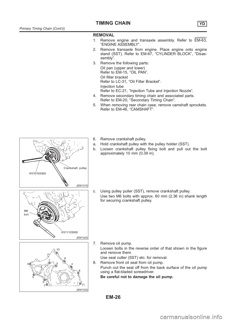
REMOVALNJEM0094S011. Remove engine and transaxle assembly. Refer to EM-63,
“ENGINE ASSEMBLY”.
2. Remove transaxle from engine. Place engine onto engine
stand (SST). Refer to EM-67, “CYLINDER BLOCK”, “Disas-
sembly”.
3. Remove the following parts:
Oil pan (upper and lower)
Refer to EM-15, “OIL PAN”.
Oil filter bracket
Refer to LC-31, “Oil Filter Bracket”.
Injection tube
Refer to EC-21, “Injection Tube and Injection Nozzle”.
4. Remove secondary timing chain and associated parts.
Refer to EM-20, “Secondary Timing Chain”.
5. When removing rear chain case, remove camshaft sprockets.
Refer to EM-46, “CAMSHAFT”.
JEM131G
6. Remove crankshaft pulley.
a. Hold crankshaft pulley with the pulley holder (SST).
b. Loosen crankshaft pulley fixing bolt and pull out the bolt
approximately 10 mm (0.39 in).
JEM132G
c. Using pulley puller (SST), remove crankshaft pulley.
Use two M6 bolts with approx. 60 mm (2.36 in) shank length
for securing crankshaft pulley.
JEM133G
7. Remove oil pump.
Loosen bolts in the reverse order of that shown in the figure
and remove them.
Use seal cutter (SST) etc. for removal.
8. Remove front oil seal from oil pump.
Punch out the seal off from the back surface of the oil pump
using a flat-bladed screwdriver.
Be careful not to damage the oil pump.
TIMING CHAINYD
Primary Timing Chain (Cont’d)
EM-26
Page 212 of 3189
JEM138G
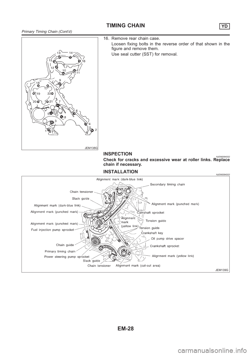
16. Remove rear chain case.
Loosen fixing bolts in the reverse order of that shown in the
figure and remove them.
Use seal cutter (SST) for removal.
INSPECTIONNJEM0094S02Check for cracks and excessive wear at roller links. Replace
chain if necessary.
INSTALLATIONNJEM0094S03
JEM139G
TIMING CHAINYD
Primary Timing Chain (Cont’d)
EM-28