Page 1417 of 3189
SMT138A
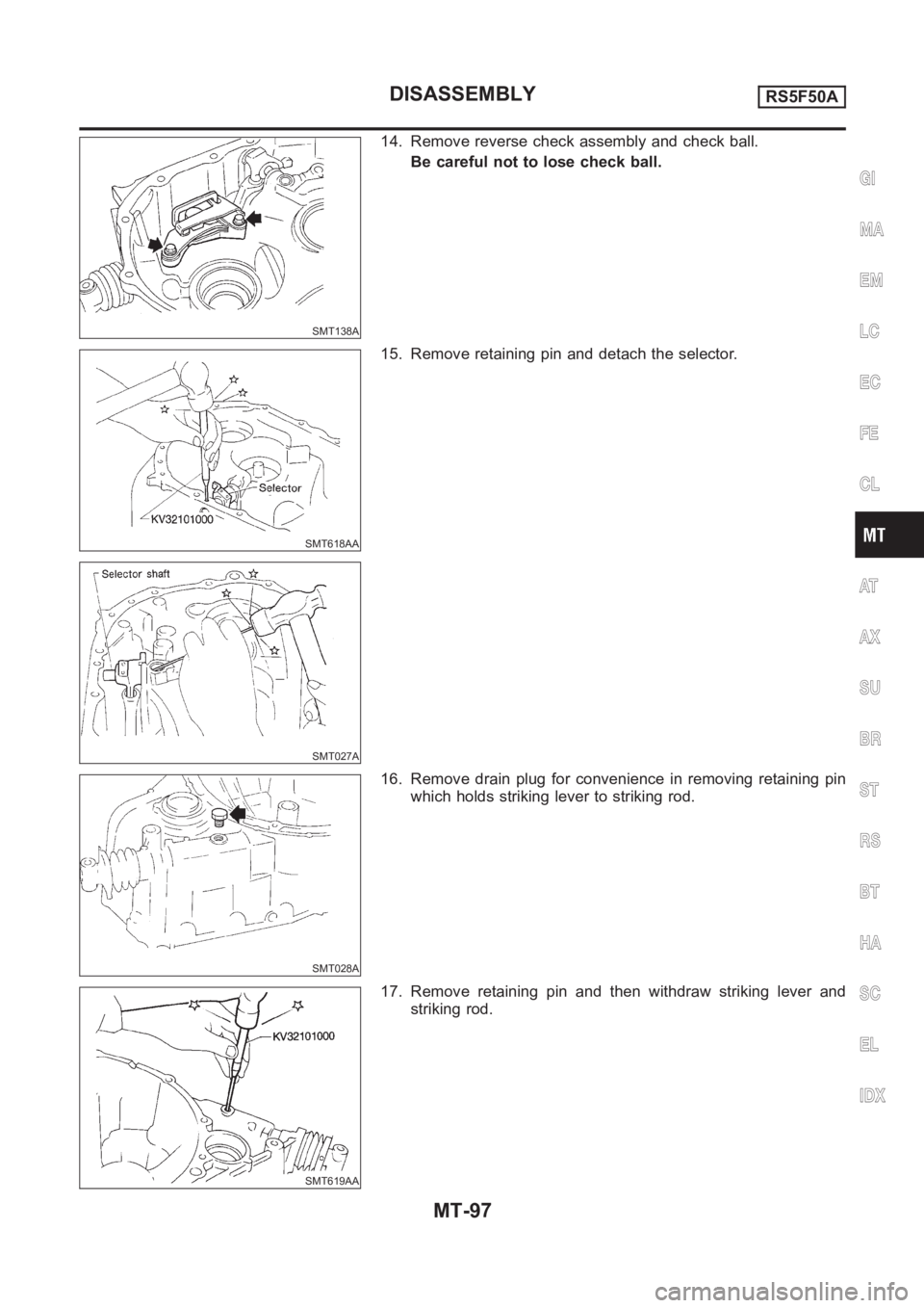
14. Remove reverse check assembly and check ball.
Be careful not to lose check ball.
SMT618AA
SMT027A
15. Remove retaining pin and detach the selector.
SMT028A
16. Remove drain plug for convenience in removing retaining pin
which holds striking lever to striking rod.
SMT619AA
17. Remove retaining pin and then withdraw striking lever and
striking rod.
GI
MA
EM
LC
EC
FE
CL
AT
AX
SU
BR
ST
RS
BT
HA
SC
EL
IDX
DISASSEMBLYRS5F50A
MT-97
Page 1418 of 3189
SMT121C
Input Shaft and Gears
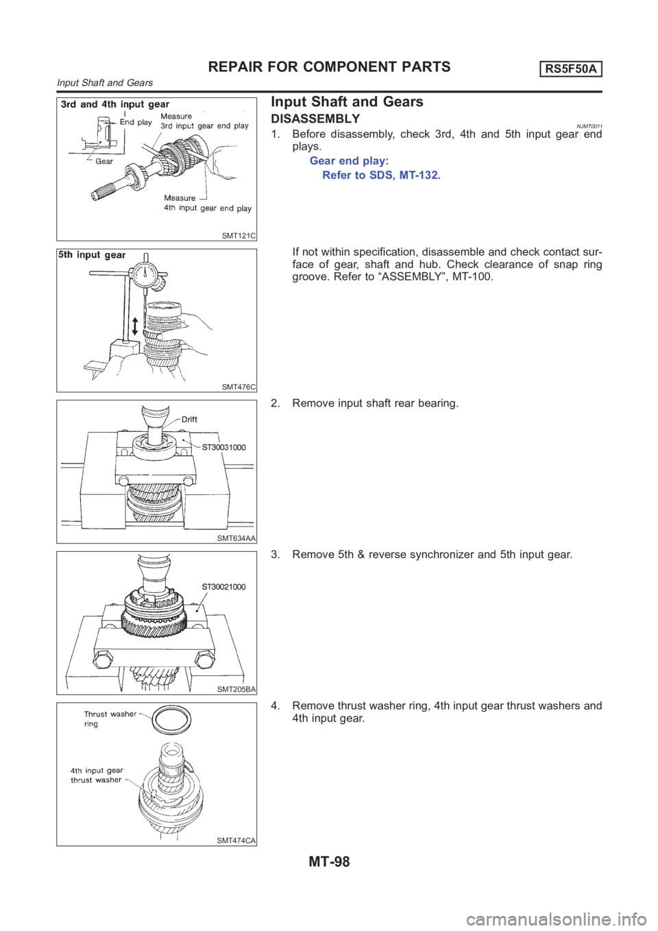
DISASSEMBLYNJMT00111. Before disassembly, check 3rd, 4th and 5th input gear end
plays.
Gear end play:
Refer to SDS, MT-132.
SMT476C
If not within specification, disassemble and check contact sur-
face of gear, shaft and hub. Check clearance of snap ring
groove. Refer to “ASSEMBLY”, MT-100.
SMT634AA
2. Remove input shaft rear bearing.
SMT205BA
3. Remove 5th & reverse synchronizer and 5th input gear.
SMT474CA
4. Remove thrust washer ring, 4th input gear thrust washers and
4th input gear.
REPAIR FOR COMPONENT PARTSRS5F50A
Input Shaft and Gears
MT-98
Page 1420 of 3189
SMT140
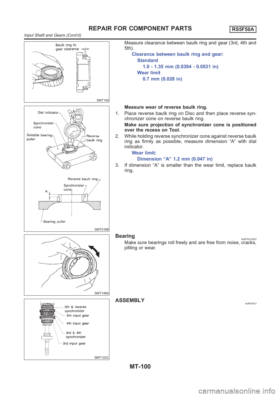
Measure clearance between baulk ring and gear (3rd, 4th and
5th).
Clearance between baulk ring and gear:
Standard
1.0 - 1.35 mm (0.0394 - 0.0531 in)
Wear limit
0.7 mm (0.028 in)
SMT516B
Measure wear of reverse baulk ring.
1. Place reverse baulk ring on Disc and then place reverse syn-
chronizer cone on reverse baulk ring.
Make sure projection of synchronizer cone is positioned
over the recess on Tool.
2. While holding reverse synchronizer cone against reverse baulk
ring as firmly as possible, measure dimension “A” with dial
indicator.
Wear limit:
Dimension “A” 1.2 mm (0.047 in)
3. If dimension “A” is smaller than the wear limit, replace baulk
ring.
SMT148A
BearingNJMT0012S03Make sure bearings roll freely and are free from noise, cracks,
pitting or wear.
SMT122C
ASSEMBLYNJMT0013
REPAIR FOR COMPONENT PARTSRS5F50A
Input Shaft and Gears (Cont’d)
MT-100
Page 1421 of 3189
SMT441C
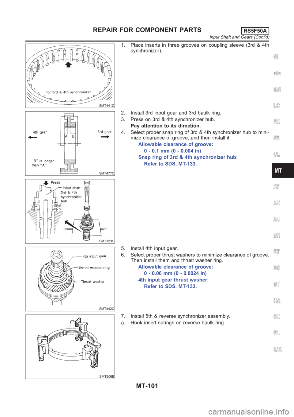
1. Place inserts in three grooves on coupling sleeve (3rd & 4th
synchronizer).
SMT477C
SMT123C
2. Install 3rd input gear and 3rd baulk ring.
3. Press on 3rd & 4th synchronizer hub.
Pay attention to its direction.
4. Select proper snap ring of 3rd & 4th synchronizer hub to mini-
mize clearance of groove, and then install it.
Allowable clearance of groove:
0-0.1mm(0-0.004in)
Snap ring of 3rd & 4th synchronizer hub:
Refer to SDS, MT-133.
SMT442C
5. Install 4th input gear.
6. Select proper thrust washers to minimize clearance of groove.
Then install them and thrust washer ring.
Allowable clearance of groove:
0 - 0.06 mm (0 - 0.0024 in)
4th input gear thrust washer:
Refer to SDS, MT-133.
SMT206B
7. Install 5th & reverse synchronizer assembly.
a. Hook insert springs on reverse baulk ring.
GI
MA
EM
LC
EC
FE
CL
AT
AX
SU
BR
ST
RS
BT
HA
SC
EL
IDX
REPAIR FOR COMPONENT PARTSRS5F50A
Input Shaft and Gears (Cont’d)
MT-101
Page 1422 of 3189
SMT752C
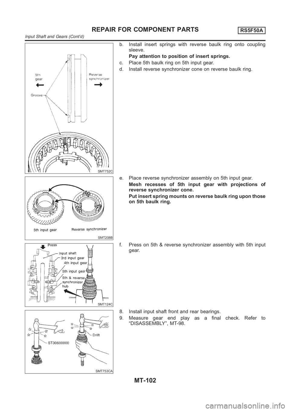
b. Install insert springs with reverse baulk ring onto coupling
sleeve.
Pay attention to position of insert springs.
c. Place 5th baulk ring on 5th input gear.
d. Install reverse synchronizer cone on reverse baulk ring.
SMT208B
e. Place reverse synchronizer assembly on 5th input gear.
Mesh recesses of 5th input gear with projections of
reverse synchronizer cone.
Put insert spring mounts on reverse baulk ring upon those
on 5th baulk ring.
SMT124C
f. Press on 5th & reverse synchronizer assembly with 5th input
gear.
SMT753CA
8. Install input shaft front and rear bearings.
9. Measure gear end play as a final check. Refer to
“DISASSEMBLY”, MT-98.
REPAIR FOR COMPONENT PARTSRS5F50A
Input Shaft and Gears (Cont’d)
MT-102
Page 1434 of 3189
NJMT0093
SMT029AA
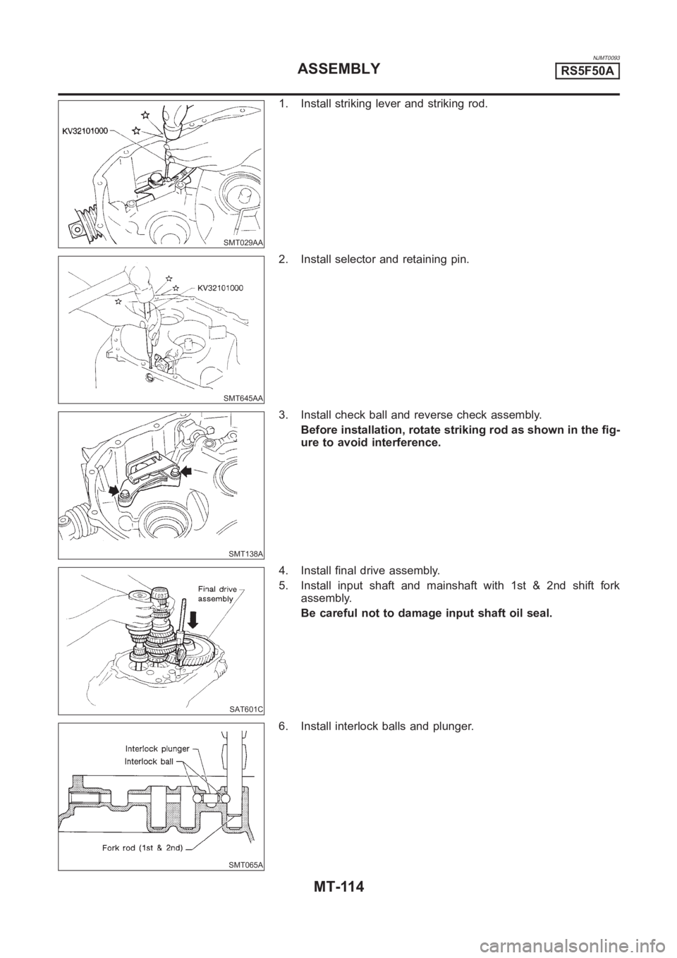
1. Install striking lever and striking rod.
SMT645AA
2. Install selector and retaining pin.
SMT138A
3. Install check ball and reverse check assembly.
Before installation, rotate striking rod as shown in the fig-
ure to avoid interference.
SAT601C
4. Install final drive assembly.
5. Install input shaft and mainshaft with 1st & 2nd shift fork
assembly.
Be careful not to damage input shaft oil seal.
SMT065A
6. Install interlock balls and plunger.
ASSEMBLYRS5F50A
MT-114
Page 1435 of 3189
SMT066A
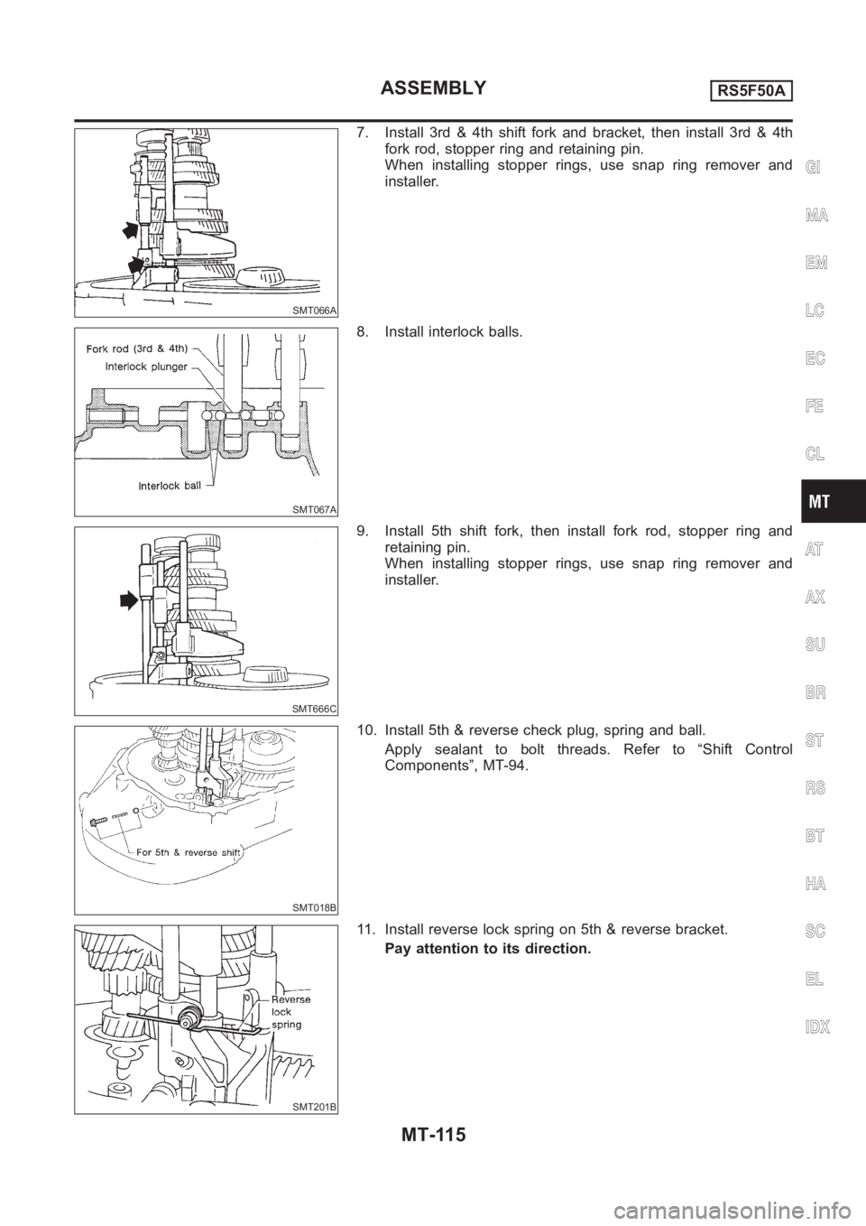
7. Install 3rd & 4th shift fork and bracket, then install 3rd & 4th
fork rod, stopper ring and retaining pin.
When installing stopper rings, use snap ring remover and
installer.
SMT067A
8. Install interlock balls.
SMT666C
9. Install 5th shift fork, then install fork rod, stopper ring and
retaining pin.
When installing stopper rings, use snap ring remover and
installer.
SMT018B
10. Install 5th & reverse check plug, spring and ball.
Apply sealant to bolt threads. Refer to “Shift Control
Components”, MT-94.
SMT201B
11. Install reverse lock spring on 5th & reverse bracket.
Pay attention to its direction.
GI
MA
EM
LC
EC
FE
CL
AT
AX
SU
BR
ST
RS
BT
HA
SC
EL
IDX
ASSEMBLYRS5F50A
MT-115
Page 1436 of 3189
SMT667C
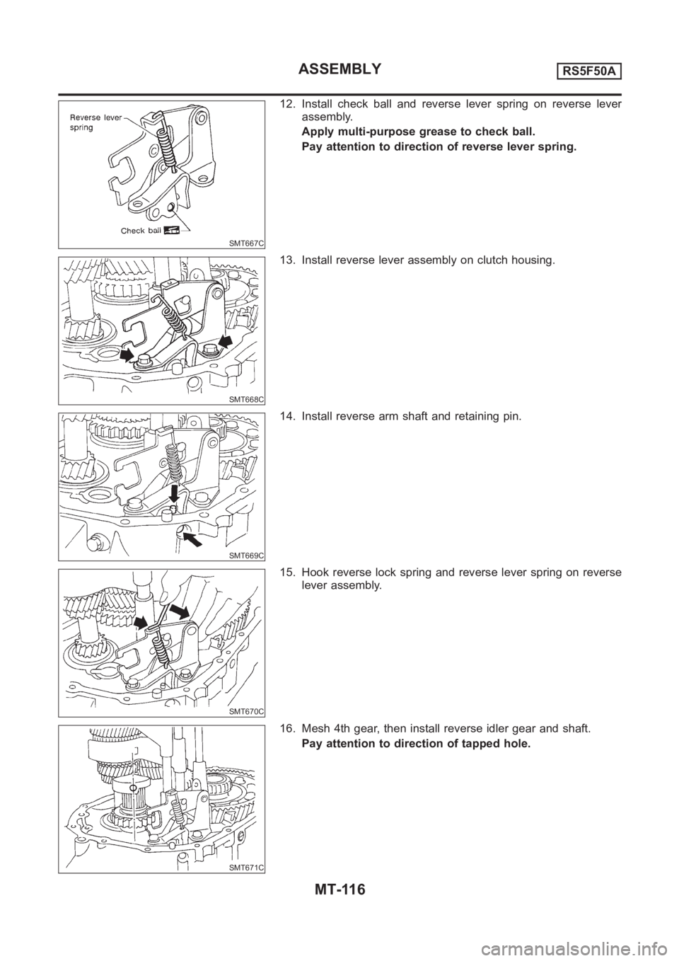
12. Install check ball and reverse lever spring on reverse lever
assembly.
Apply multi-purpose grease to check ball.
Pay attention to direction of reverse lever spring.
SMT668C
13. Install reverse lever assembly on clutch housing.
SMT669C
14. Install reverse arm shaft and retaining pin.
SMT670C
15. Hook reverse lock spring and reverse lever spring on reverse
lever assembly.
SMT671C
16. Mesh 4th gear, then install reverse idler gear and shaft.
Pay attention to direction of tapped hole.
ASSEMBLYRS5F50A
MT-116