2003 NISSAN ALMERA N16 cooling fan
[x] Cancel search: cooling fanPage 3029 of 3189
SHA708EA
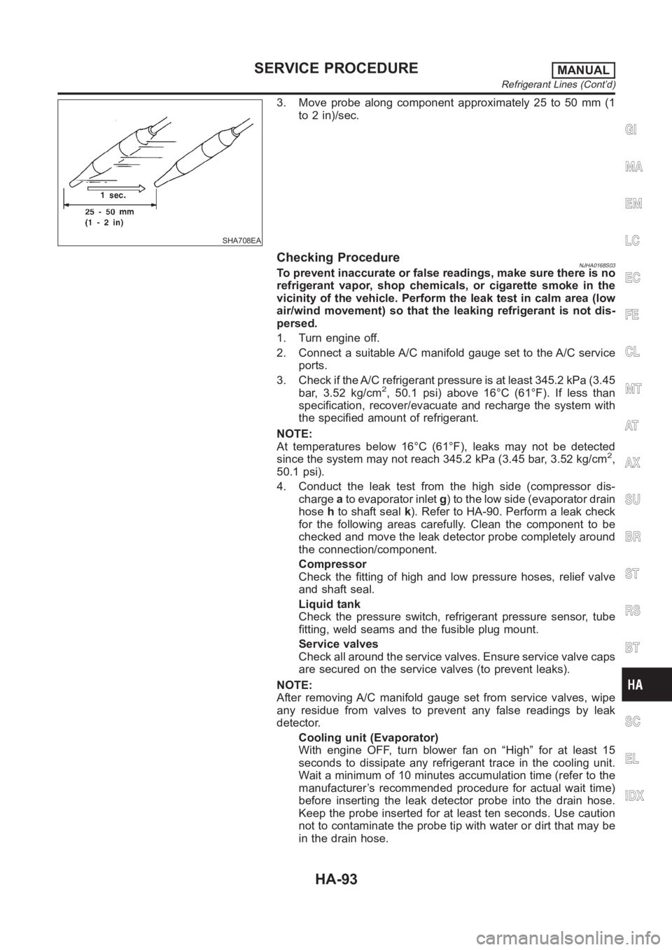
3. Move probe along component approximately 25 to 50 mm (1
to 2 in)/sec.
Checking ProcedureNJHA0168S03To prevent inaccurate or false readings, make sure there is no
refrigerant vapor, shop chemicals, or cigarette smoke in the
vicinity of the vehicle. Perform the leak test in calm area (low
air/wind movement) so that the leaking refrigerant is not dis-
persed.
1. Turn engine off.
2. Connect a suitable A/C manifold gauge set to the A/C service
ports.
3. Check if the A/C refrigerant pressure is at least 345.2 kPa (3.45
bar, 3.52 kg/cm
2, 50.1 psi) above 16°C (61°F). If less than
specification, recover/evacuate and recharge the system with
the specified amount of refrigerant.
NOTE:
At temperatures below 16°C (61°F), leaks may not be detected
since the system may not reach 345.2 kPa (3.45 bar, 3.52 kg/cm
2,
50.1 psi).
4. Conduct the leak test from the high side (compressor dis-
chargeato evaporator inletg) to the low side (evaporator drain
hosehto shaft sealk). Refer to HA-90. Perform a leak check
for the following areas carefully. Clean the component to be
checked and move the leak detector probe completely around
the connection/component.
Compressor
Check the fitting of high and low pressure hoses, relief valve
and shaft seal.
Liquid tank
Check the pressure switch, refrigerant pressure sensor, tube
fitting, weld seams and the fusible plug mount.
Service valves
Check all around the service valves. Ensure service valve caps
are secured on the service valves (to prevent leaks).
NOTE:
After removing A/C manifold gauge set from service valves, wipe
any residue from valves to prevent any false readings by leak
detector.
Cooling unit (Evaporator)
With engine OFF, turn blower fan on “High” for at least 15
seconds to dissipate any refrigerant trace in the cooling unit.
Wait a minimum of 10 minutes accumulation time (refer to the
manufacturer’s recommended procedure for actual wait time)
before inserting the leak detector probe into the drain hose.
Keep the probe inserted for at least ten seconds. Use caution
not to contaminate the probe tip with water or dirt that may be
in the drain hose.
GI
MA
EM
LC
EC
FE
CL
MT
AT
AX
SU
BR
ST
RS
BT
SC
EL
IDX
SERVICE PROCEDUREMANUAL
Refrigerant Lines (Cont’d)
HA-93
Page 3178 of 3189
COOL/F - Wiring diagram
(QG engine)................................EC-328, EC-601
COOL/F - Wiring diagram (YD engine) ........EC-130
Coolant mixture ratio......................................MA-21
Cooling circuit (engine).............................LC-12, 36
Cooling fan control (YD engine)...................EC-130
Cooling fan control system .......................LC-17, 42
Cooling fan motor (QG engine) .....EC-335, EC-608
Coupling sleeve (M/T)........................MT-31, 55, 93
Crankcase emission control system -
See positive crankcase ventilation
(YD engine).................................................EC-19
Crankcase ventilation system - See
Positive crankcase ventilation
(QG engine)................................EC-403, EC-722
Crankcase ventilation system - See
Positive crankcase ventilation
(YD engine).................................................EC-19
Crankshaft (QG engine).................................EM-71
Crankshaft (YD engine) .................................EM-75
Crankshaft position sensor (POS)
(QG engine)................................EC-235, EC-556
Crankshaft position sensor (TDC)
(YD engine).................................................EC-99
Cylinder block (QG engine) ...........................EM-70
Cylinder block (YD engine) ............................EM-66
Cylinder block boring (QG engine) ................EM-88
Cylinder block boring(QR) .............................EM-89
Cylinder head (QG engine)............................EM-57
Cylinder head (YD engine) ............................EM-45
Cylinder head bolt tightening
(QG engine)................................................EM-59
D
Data link connector
(QG engine) ...EC-398, EC-399, EC-717, EC-718
Data link connector for Consult
(QG engine)..................................EC-90, EC-468
Data link connector for Consult
(YD engine).................................................EC-39
Daytime light system.......................................EL-46
DEF - Wiring diagram ...................................EL-176
Diagnosis sensor unit .....................................RS-26
Diagnostic trouble code (DTC) for OBD
system (QG engine) ......................EC-10, EC-39,
EC-407, EC-430
Diagnostic trouble code (DTC) for OBD
system (YD engine) ................................EC-4, 34
Diagnostic trouble code (DTC) inspec-
tion priority chart (QG engine) .....EC-62, EC-441
Differential gear (FF M/T) ....MT-31, 43, 55, 93, 107
Dimensions <0011001100110011001100110011001100110011001100110011001100110011001100110011001100110011001100110011001100110011001100110011001100110011001100110011001100110011001100110011001100110011001100110011001100
1100110011[.GI-44
Dome light - See Interior lamp .......................EL-80
Door glass <0011001100110011001100110011001100110011001100110011001100110011001100110011001100110011001100110011001100110011001100110011001100110011001100110011001100110011001100110011001100110011001100110011001100
11001100110011[.BT-17
Door lock <0011001100110011001100110011001100110011001100110011001100110011001100110011001100110011001100110011001100110011001100110011001100110011001100110011001100110011001100110011001100110011001100110011001100
110011001100110011[..BT-21
Door mirror <0011001100110011001100110011001100110011001100110011001100110011001100110011001100110011001100110011001100110011001100110011001100110011001100110011001100110011001100110011001100110011001100110011001100
1100110011[.BT-72
Door trim <0011001100110011001100110011001100110011001100110011001100110011001100110011001100110011001100110011001100110011001100110011001100110011001100110011001100110011001100110011001100110011001100110011001100
110011001100110011[..BT-39
Door, front <0011001100110011001100110011001100110011001100110011001100110011001100110011001100110011001100110011001100110011001100110011001100110011001100110011001100110011001100110011001100110011001100110011001100
1100110011[..BT-16
Door, rear <0011001100110011001100110011001100110011001100110011001100110011001100110011001100110011001100110011001100110011001100110011001100110011001100110011001100110011001100110011001100110011001100110011001100
11001100110011[..BT-16Drive belt (QG engine) ...................................EM-11
Drive shaft (front)............................................AX-10
Dropping resistor (A/T) ....................AT-171, AT-395
DTC work support (QG engine) .....................EC-97
Dual pressure switch (manual A/C) ...............HA-12
Dual pressure switch ......ATC-15, ATC-86, ATC-144
Duct and grilles...........................................ATC-131
E
ECCS-D control module
(YD engine) ........EC-66, 116, 175, 177, 181, 183
ECM input/output signal
(QG engine)..................................EC-81, EC-460
ECM input/output signal (YD engine) ............EC-66
ECM power supply
(QG engine) ...EC-111, EC-269, EC-488, EC-573
ECM/PW - Wiring diagram
(QG engine)................................EC-270, EC-574
ECTS - Wiring diagram
(QG engine)................................EC-147, EC-505
ECTS - Wiring diagram (YD engine)..............EC-84
EGR volume control valve (YD engine) .......EC-197
EGRC1 - Wiring diagram (YD engine) .........EC-199
Electric sun roof ............................................EL-249
Electric throttle control actuator
(QG engine) ................EC-277, EC-279, EC-292,
EC-577, EC-580, EC-593
Electrical diagnoses.........................................GI-22
Electrical load signal circuit
(QG engine)................................EC-393, EC-712
Electrical unit ................................................Foldout
Electrical units location .................................EL-543
Electronic fuel injection pump
(YD engine) ...............EC-25, 118, 124, 145, 151,
157, 163, 169, 185
Electronic ignition (EI) system
(QG engine)..................................EC-25, EC-420
Engine compartment .......................................BT-75
Engine control circuit diagram
(QG engine)..................................EC-79, EC-458
Engine control circuit diagram
(YD engine).................................................EC-14
Engine control component parts loca-
tion (QG engine)...........................EC-75, EC-454
Engine control component parts loca-
tion (YD engine) ..........................................EC-11
Engine control module (ECM)
(QG engine)................................EC-266, EC-570
Engine control module (ECM)
(YD engine) ........EC-66, 116, 175, 177, 181, 183
Engine control system diagram and
chart (QG engine) ........................EC-21, EC-416
Engine control system diagram and
chart (YD engine) .......................................EC-15
Engine coolant temperature sensor
(ECTS) (QG engine) ..................EC-145, EC-503
Engine coolant temperature sensor
(ECTS) (YD engine) ...................................EC-84
ALPHABETICAL INDEX
IDX-4