2003 NISSAN ALMERA N16 crankshaft
[x] Cancel search: crankshaftPage 265 of 3189
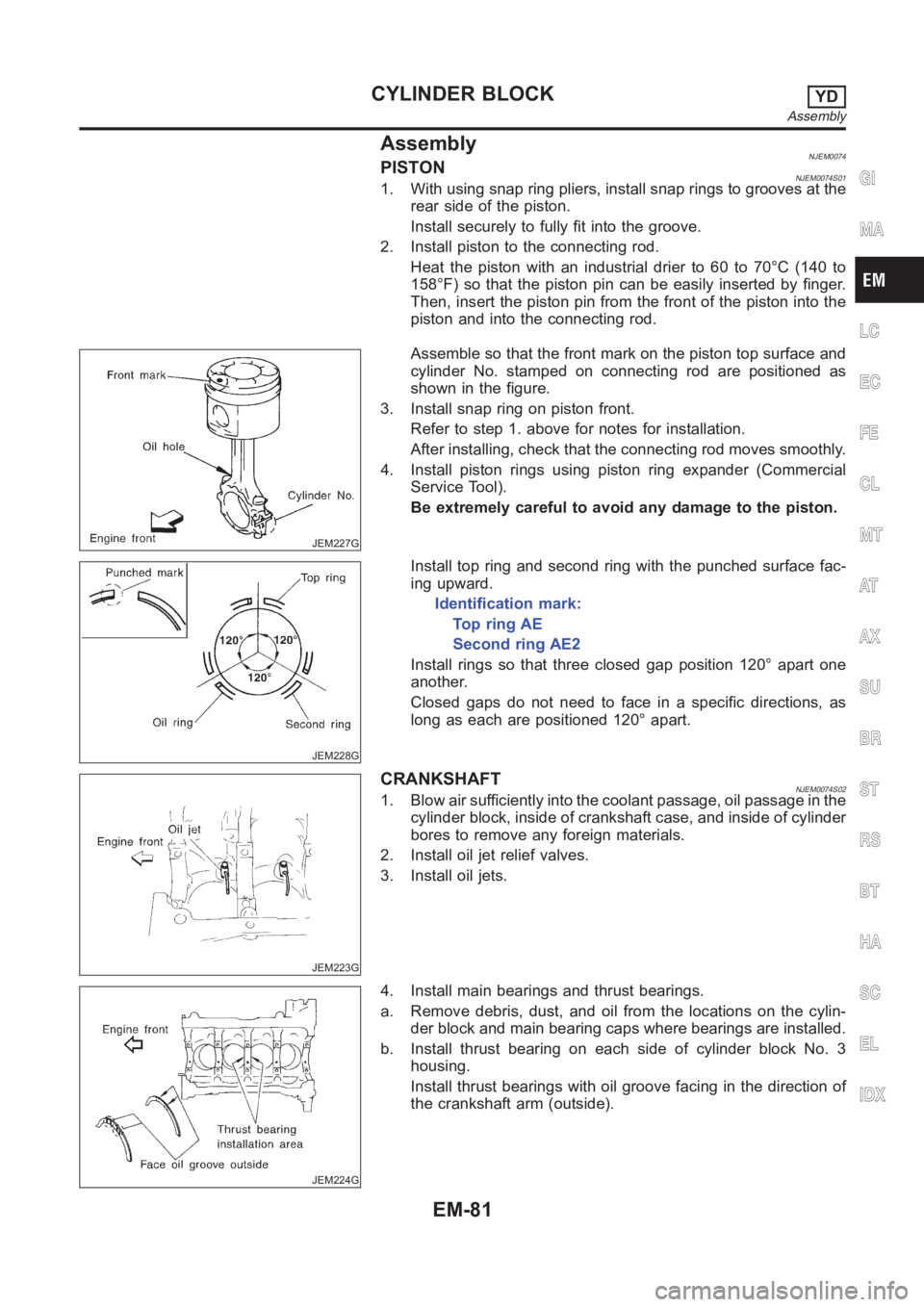
AssemblyNJEM0074PISTONNJEM0074S011. With using snap ring pliers, install snap rings to grooves at the
rear side of the piston.
Install securely to fully fit into the groove.
2. Install piston to the connecting rod.
Heat the piston with an industrial drier to 60 to 70°C (140 to
158°F) so that the piston pin can be easily inserted by finger.
Then, insert the piston pin from the front of the piston into the
piston and into the connecting rod.
JEM227G
Assemble so that the front mark on the piston top surface and
cylinder No. stamped on connecting rod are positioned as
shown in the figure.
3. Install snap ring on piston front.
Refer to step 1. above for notes for installation.
After installing, check that the connecting rod moves smoothly.
4. Install piston rings using piston ring expander (Commercial
Service Tool).
Be extremely careful to avoid any damage to the piston.
JEM228G
Install top ring and second ring with the punched surface fac-
ing upward.
Identification mark:
Top ring AE
Second ring AE2
Install rings so that three closed gap position 120° apart one
another.
Closed gaps do not need to face in a specific directions, as
long as each are positioned 120° apart.
JEM223G
CRANKSHAFTNJEM0074S021. Blow air sufficiently into the coolant passage, oil passage in the
cylinder block, inside of crankshaft case, and inside of cylinder
bores to remove any foreign materials.
2. Install oil jet relief valves.
3. Install oil jets.
JEM224G
4. Install main bearings and thrust bearings.
a. Remove debris, dust, and oil from the locations on the cylin-
der block and main bearing caps where bearings are installed.
b. Install thrust bearing on each side of cylinder block No. 3
housing.
Install thrust bearings with oil groove facing in the direction of
the crankshaft arm (outside).
GI
MA
LC
EC
FE
CL
MT
AT
AX
SU
BR
ST
RS
BT
HA
SC
EL
IDX
CYLINDER BLOCKYD
Assembly
EM-81
Page 266 of 3189
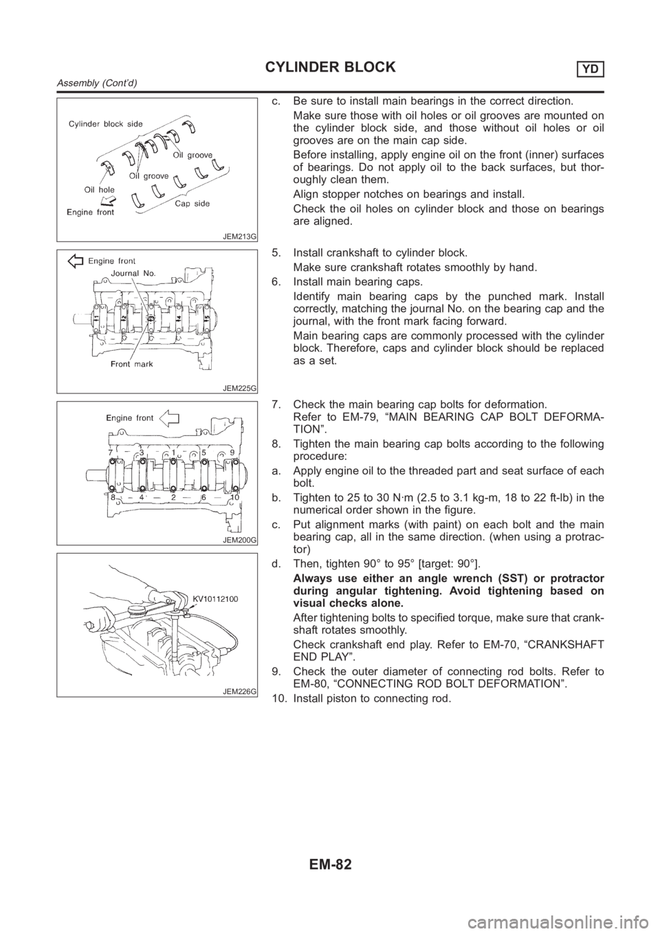
JEM213G
c. Be sure to install main bearings in the correct direction.
Make sure those with oil holes or oil grooves are mounted on
the cylinder block side, and those without oil holes or oil
grooves are on the main cap side.
Before installing, apply engine oil on the front (inner) surfaces
of bearings. Do not apply oil to the back surfaces, but thor-
oughly clean them.
Align stopper notches on bearings and install.
Check the oil holes on cylinder block and those on bearings
are aligned.
JEM225G
5. Install crankshaft to cylinder block.
Make sure crankshaft rotates smoothly by hand.
6. Install main bearing caps.
Identify main bearing caps by the punched mark. Install
correctly, matching the journal No. on the bearing cap and the
journal, with the front mark facing forward.
Main bearing caps are commonly processed with the cylinder
block. Therefore, caps and cylinder block should be replaced
as a set.
JEM200G
JEM226G
7. Check the main bearing cap bolts for deformation.
Refer to EM-79, “MAIN BEARING CAP BOLT DEFORMA-
TION”.
8. Tighten the main bearing cap bolts according to the following
procedure:
a. Apply engine oil to the threaded part and seat surface of each
bolt.
b. Tighten to 25 to 30 N·m (2.5 to 3.1 kg-m, 18 to 22 ft-lb) in the
numerical order shown in the figure.
c. Put alignment marks (with paint) on each bolt and the main
bearing cap, all in the same direction. (when using a protrac-
tor)
d. Then, tighten 90° to 95° [target: 90°].
Always use either an angle wrench (SST) or protractor
during angular tightening. Avoid tightening based on
visual checks alone.
After tightening bolts to specified torque, make sure that crank-
shaft rotates smoothly.
Check crankshaft end play. Refer to EM-70, “CRANKSHAFT
END PLAY”.
9. Check the outer diameter of connecting rod bolts. Refer to
EM-80, “CONNECTING ROD BOLT DEFORMATION”.
10. Install piston to connecting rod.
CYLINDER BLOCKYD
Assembly (Cont’d)
EM-82
Page 267 of 3189
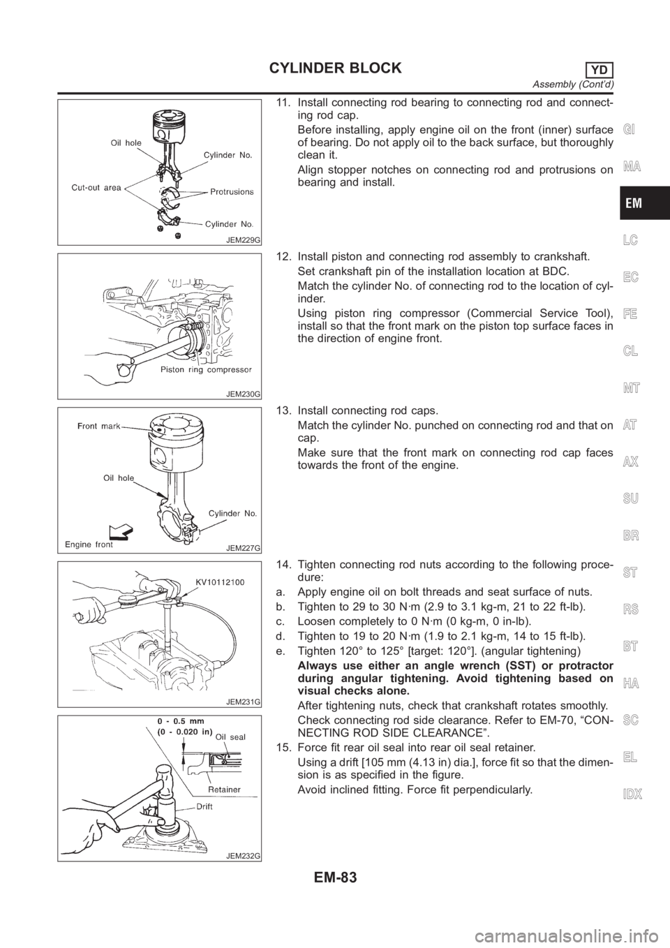
JEM229G
11. Install connecting rod bearing to connecting rod and connect-
ing rod cap.
Before installing, apply engine oil on the front (inner) surface
of bearing. Do not apply oil to the back surface, but thoroughly
clean it.
Align stopper notches on connecting rod and protrusions on
bearing and install.
JEM230G
12. Install piston and connecting rod assembly to crankshaft.
Set crankshaft pin of the installation location at BDC.
Match the cylinder No. of connecting rod to the location of cyl-
inder.
Using piston ring compressor (Commercial Service Tool),
install so that the front mark on the piston top surface faces in
the direction of engine front.
JEM227G
13. Install connecting rod caps.
Match the cylinder No. punched on connecting rod and that on
cap.
Make sure that the front mark on connecting rod cap faces
towards the front of the engine.
JEM231G
JEM232G
14. Tighten connecting rod nuts according to the following proce-
dure:
a. Apply engine oil on bolt threads and seat surface of nuts.
b. Tighten to 29 to 30 N·m (2.9 to 3.1 kg-m, 21 to 22 ft-lb).
c. Loosen completely to 0 N·m (0 kg-m, 0 in-lb).
d. Tighten to 19 to 20 N·m (1.9 to 2.1 kg-m, 14 to 15 ft-lb).
e. Tighten 120° to 125° [target: 120°]. (angular tightening)
Always use either an angle wrench (SST) or protractor
during angular tightening. Avoid tightening based on
visual checks alone.
After tightening nuts, check that crankshaft rotates smoothly.
Check connecting rod side clearance. Refer to EM-70, “CON-
NECTING ROD SIDE CLEARANCE”.
15. Force fit rear oil seal into rear oil seal retainer.
Using a drift [105 mm (4.13 in) dia.], force fit so that the dimen-
sion is as specified in the figure.
Avoid inclined fitting. Force fit perpendicularly.
GI
MA
LC
EC
FE
CL
MT
AT
AX
SU
BR
ST
RS
BT
HA
SC
EL
IDX
CYLINDER BLOCKYD
Assembly (Cont’d)
EM-83
Page 279 of 3189
![NISSAN ALMERA N16 2003 Electronic Repair Manual Connecting RodNJEM0083Unit: mm (in)
Center distance157.5 (6.201)
Bend [per 100 (3.94)] Limit 0.12 (0.0047)
Torsion [per 100 (3.94)] Limit 0.12 (0.0047)
Connecting rod small end inner diameter 30.080 - NISSAN ALMERA N16 2003 Electronic Repair Manual Connecting RodNJEM0083Unit: mm (in)
Center distance157.5 (6.201)
Bend [per 100 (3.94)] Limit 0.12 (0.0047)
Torsion [per 100 (3.94)] Limit 0.12 (0.0047)
Connecting rod small end inner diameter 30.080 -](/manual-img/5/57350/w960_57350-278.png)
Connecting RodNJEM0083Unit: mm (in)
Center distance157.5 (6.201)
Bend [per 100 (3.94)] Limit 0.12 (0.0047)
Torsion [per 100 (3.94)] Limit 0.12 (0.0047)
Connecting rod small end inner diameter 30.080 - 31.000 (1.1842 - 1.2205)
Piston pin bushing inner diameter* 28.026 - 28.038 (1.1034 - 1.1039)
Connecting rod big end inner diameter 55.000 - 55.013 (2.1654 - 2.1659)
Side clearanceStandard 0.200 - 0.350 (0.0079 - 0.0138)
Limit 0.4 (0.016)
*: After installing in connecting rod
CrankshaftNJEM0084Unit: mm (in)
Main journal dia. “Dm” gradeGrade No. 0
Grade No. 1
Grade No. 262.967 - 62.975 (2.4790 - 2.4793)
62.959 - 62.967 (2.4787 - 2.4790)
62.951 - 62.959 (2.4784 - 2.4787)
Pin journal dia. “Dp”Grade No. 0 51.968 - 51.974 (2.0460 - 2.0462)
Grade No. 1 51.961 - 51.968 (2.0457 - 2.0460)
Grade No. 2 51.954 - 51.961 (2.0454 - 2.0457)
Center distance “r”46.97 - 47.03 (1.8492 - 1.8516)
Out-of-round (X − Y) Standard/Limit Less than 0.003 (0.0001)/Less than 0.005 (0.0002)
Taper (A − B) Standard/Limit Less than 0.003 (0.0001)/Less than 0.005 (0.0002)
Runout [TIR*]Standard Less than 0.05 (0.0020)
Limit Less than 0.10 (0.0039)
Free end playStandard 0.10 - 0.25 (0.0039 - 0.0098)
Limit 0.30 (0.0118)
SEM645EM715
*: Total indicator reading
GI
MA
LC
EC
FE
CL
MT
AT
AX
SU
BR
ST
RS
BT
HA
SC
EL
IDX
SERVICE DATA AND SPECIFICATIONS (SDS)YD
Connecting Rod
EM-95
Page 335 of 3189
EC-5
C
D
E
F
G
H
I
J
K
L
M
ECA Wiring Diagram .................................................... 353
Diagnostic Procedure ........................................... 354
DTC P1706 PNP SWITCH ...................................... 356
Component Description ........................................ 356
CONSULT-II Reference Value in Data Monitor Mode
. 356
On Board Diagnosis Logic ................................... 356
DTC Confirmation Procedure ............................... 356
Overall Function Check ........................................ 357
Wiring Diagram .................................................... 358
Diagnostic Procedure ........................................... 359
DTC P1805 BRAKE SWITCH ................................ 360
Description ........................................................... 360
CONSULT-II Reference Value in Data Monitor Mode
. 360
On Board Diagnosis Logic ................................... 360
DTC Confirmation Procedure ............................... 360
Wiring Diagram .................................................... 361
Diagnostic Procedure ........................................... 362
Component Inspection ......................................... 364
IGNITION SIGNAL .................................................. 365
Component Description ........................................ 365
Wiring Diagram .................................................... 366
Diagnostic Procedure ........................................... 369
Component Inspection ......................................... 373
Removal and Installation ...................................... 374
INJECTOR CIRCUIT ............................................... 375
Component Description ........................................ 375
CONSULT-II Reference Value in Data Monitor Mode
. 375
Wiring Diagram .................................................... 376
Diagnostic Procedure ........................................... 377
Component Inspection ......................................... 380
Removal and Installation ...................................... 380
FUEL PUMP CIRCUIT ............................................ 381
Description ........................................................... 381
CONSULT-II Reference Value in Data Monitor Mode
. 381
Wiring Diagram .................................................... 382
Diagnostic Procedure ........................................... 383
Component Inspection ......................................... 385
Removal and Installation ...................................... 386
REFRIGERANT PRESSURE SENSOR ................. 387
Component Description ........................................ 387
Wiring Diagram .................................................... 388
Diagnostic Procedure ........................................... 389
Removal and Installation ...................................... 391
ELECTRICAL LOAD SIGNAL ................................ 392
Description ...................................................
........ 392
CONSULT-II Reference Value in Data Monitor Mode
. 392
Wiring Diagram .................................................... 393
Diagnostic Procedure ........................................... 394
MI & DATA LINK CONNECTORS .......................... 397
Wiring Diagram—LHD Models ............................. 397
Wiring Diagram—RHD Models ............................ 398
EVAPORATIVE EMISSION SYSTEM ..................... 399
Description ........................................................... 399
Component Inspection ......................................... 401POSITIVE CRANKCASE VENTILATION ...............402
Description ............................................................402
Component Inspection ..........................................402
SERVICE DATA AND SPECIFICATIONS (SDS) ....404
Fuel Pressure .......................................................404
Idle Speed and Ignition Timing .............................404
Calculated Load Value ..........................................404
Mass Air Flow Sensor ...........................................404
Intake Air Temperature Sensor .............................404
Engine Coolant Temperature Sensor ...................404
Heated Oxygen Sensor 1 Heater .........................404
Heated Oxygen sensor 2 Heater ..........................404
Crankshaft Position Sensor (POS) .......................404
Camshaft Position Sensor (PHASE) ....................404
Throttle Control Motor ...........................................405
Injector ..................................................................405
Fuel Pump ............................................................405
QG (WITHOUT EURO-OBD)
INDEX FOR DTC .....................................................406
Alphabetical Index ................................................406
DTC No. Index ......................................................407
PRECAUTIONS ......................................................409
Precautions for Supplemental Restraint System
(SRS) “AIR BAG” and “SEAT BELT PRE-TEN-
SIONER” ...............................................................409
On Board Diagnostic (OBD) System of Engine ....409
Precaution ............................................................409
Wiring Diagrams and Trouble Diagnosis ..............412
PREPARATION .......................................................413
Special Service Tools ...........................................413
Commercial Service Tools ....................................413
ENGINE CONTROL SYSTEM ................................415
System Diagram ...................................................415
Vacuum Hose Drawing .........................................416
System Chart ........................................................417
Multiport Fuel Injection (MFI) System ...................417
Electronic Ignition (EI) System .............................419
Air Conditioning Cut Control .................................420
Fuel Cut Control (at No Load and High Engine
Speed) ..................................................................421
CAN Communication ............................................421
BASIC SERVICE PROCEDURE .............................424
Idle Speed and Ignition Timing Check ..................424
Accelerator Pedal Released Position Learning ....425
Throttle Valve Closed Position Learning ...............425
Idle Air Volume Learning ......................................425
Fuel Pressure Check ............................................427
ON BOARD DIAGNOSTIC (OBD) SYSTEM ..........429
Introduction ...........................................................429
Two Trip Detection Logic ......................................429
Emission-related Diagnostic Information ..............429
NATS (Nissan Anti-theft System) .........................431
Malfunction Indicator (MI) .....................................432
TROUBLE DIAGNOSIS ..........................................436
Trouble Diagnosis Introduction .............................436
DTC Inspection Priority Chart ...............................440
Fail-safe Chart ......................................................441
Page 339 of 3189
EC-9
C
D
E
F
G
H
I
J
K
L
M
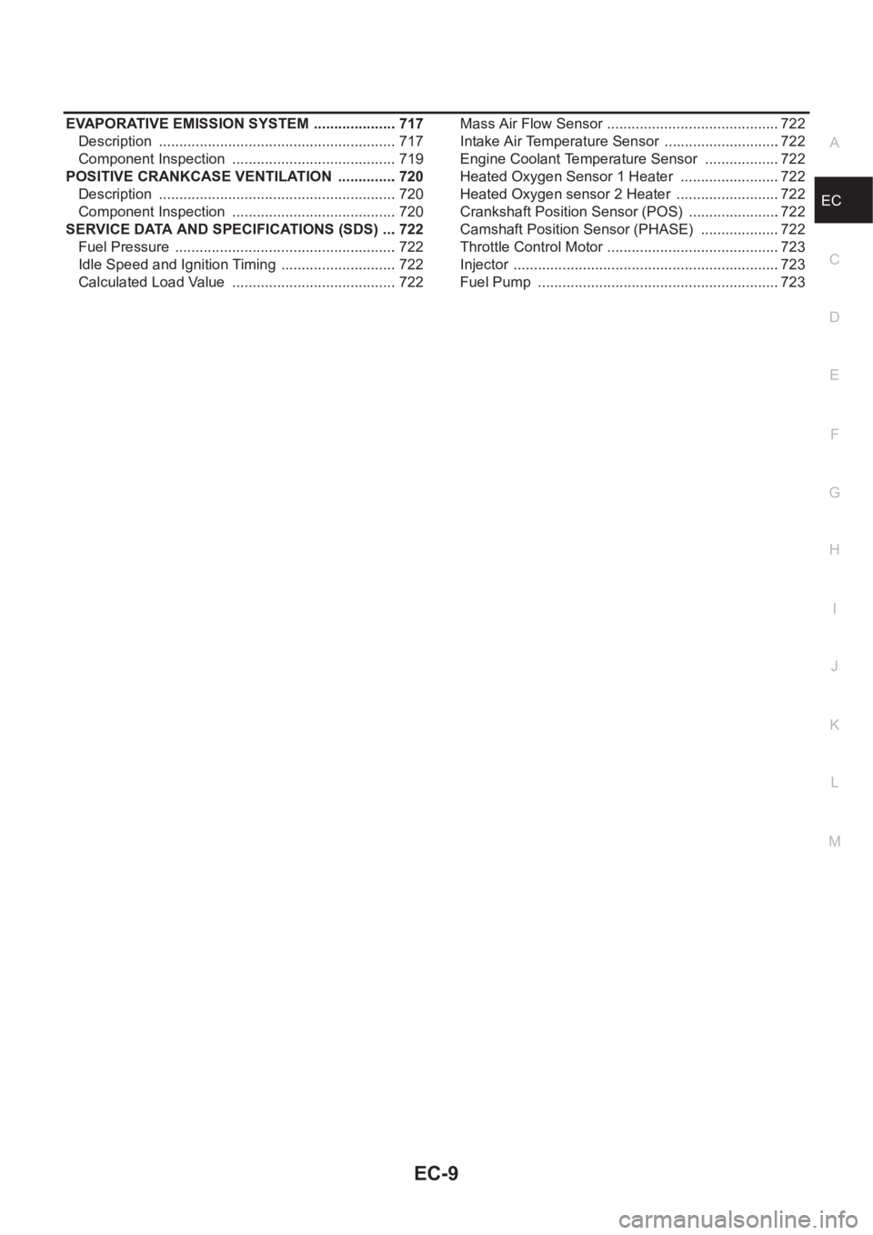
ECA EVAPORATIVE EMISSION SYSTEM ..................... 717
Description ........................................................... 717
Component Inspection ......................................... 719
POSITIVE CRANKCASE VENTILATION ............... 720
Description ........................................................... 720
Component Inspection ......................................... 720
SERVICE DATA AND SPECIFICATIONS (SDS) .... 722
Fuel Pressure ....................................................... 722
Idle Speed and Ignition Timing ............................. 722
Calculated Load Value ......................................... 722Mass Air Flow Sensor ...........................................722
Intake Air Temperature Sensor .............................722
Engine Coolant Temperature Sensor ...................722
Heated Oxygen Sensor 1 Heater .........................722
Heated Oxygen sensor 2 Heater ..........................722
Crankshaft Position Sensor (POS) .......................722
Camshaft Position Sensor (PHASE) ....................722
Throttle Control Motor ...........................................723
Injector ..................................................................723
Fuel Pump ............................................................723
Page 346 of 3189
![NISSAN ALMERA N16 2003 Electronic Repair Manual EC-16
[QG (WITH EURO-OBD)]
PRECAUTIONS
●Do not disassemble ECM.
●If battery cable is disconnected, the memory will return to
the initial ECM values.
The ECM will now start to self-c NISSAN ALMERA N16 2003 Electronic Repair Manual EC-16
[QG (WITH EURO-OBD)]
PRECAUTIONS
●Do not disassemble ECM.
●If battery cable is disconnected, the memory will return to
the initial ECM values.
The ECM will now start to self-c](/manual-img/5/57350/w960_57350-345.png)
EC-16
[QG (WITH EURO-OBD)]
PRECAUTIONS
●Do not disassemble ECM.
●If battery cable is disconnected, the memory will return to
the initial ECM values.
The ECM will now start to self-control at its initial values.
Engine operation can vary slightly when the cable is dis-
connected. However, this is not an indication of a malfunc-
tion. Do not replace parts because of a slight variation.
●When connecting ECM harness connector, fasten it
securely with levers as far as they will go as shown at right.
●When connecting or disconnecting pin connectors into or
from ECM, take care not to damage pin terminals (bend or
break).
Make sure that there are not any bends or breaks on ECM
pin terminal, when connecting pin connectors.
●Securely connect ECM harness connectors.
A poor connection can cause an extremely high (surge)
voltage to develop in coil and condenser, thus resulting in
damage to ICs.
●Keep engine control system harness at least 10 cm (4 in)
away from adjacent harness, to prevent engine control sys-
tem malfunctions due to receiving external noise, degraded
operation of ICs, etc.
●Keep engine control system parts and harness dry.
●Before replacing ECM, perform “ECM Terminals and Refer-
ence Value” inspection and make sure ECM functions prop-
erly. Refer to EC-80, "
ECM Terminals and Reference Value" .
●Handle mass air flow sensor carefully to avoid damage.
●Do not disassemble mass air flow sensor.
●Do not clean mass air flow sensor with any type of deter-
gent.
●Do not disassemble electric throttle control actuator.
●Even a slight leak in the air intake system can cause seri-
ous incidents.
●Do not shock or jar the camshaft position sensor (PHASE),
crankshaft position sensor (POS).
PBIB1164E
MBIB0145E
PBIB0090E
MEF040D
Page 353 of 3189
![NISSAN ALMERA N16 2003 Electronic Repair Manual ENGINE CONTROL SYSTEM
EC-23
[QG (WITH EURO-OBD)]
C
D
E
F
G
H
I
J
K
L
MA
EC
System ChartEBS00K34
*1: This sensor is not used to control the engine system under normal conditions.
*2: The signals are se NISSAN ALMERA N16 2003 Electronic Repair Manual ENGINE CONTROL SYSTEM
EC-23
[QG (WITH EURO-OBD)]
C
D
E
F
G
H
I
J
K
L
MA
EC
System ChartEBS00K34
*1: This sensor is not used to control the engine system under normal conditions.
*2: The signals are se](/manual-img/5/57350/w960_57350-352.png)
ENGINE CONTROL SYSTEM
EC-23
[QG (WITH EURO-OBD)]
C
D
E
F
G
H
I
J
K
L
MA
EC
System ChartEBS00K34
*1: This sensor is not used to control the engine system under normal conditions.
*2: The signals are sent to the ECM through CAN communication line.
*3: The output signals are sent from the ECM through CAN communication line.
Multiport Fuel Injection (MFI) SystemEBS00K35
INPUT/OUTPUT SIGNAL CHART
*1: Under normal conditions, this sensor is not for engine control operation.
*2: This signal is sent to the ECM through CAN communication line.
*3: ECM determines the start signal status by the signals of engine speed and battery voltage.
SYSTEM DESCRIPTION
The amount of fuel injected from the fuel injector is determined by the ECM. The ECM controls the length of
time the valve remains open (injection pulse duration). The amount of fuel injected is a program value in the
Input (Sensor) ECM Function Output (Actuator)
●Camshaft position sensor (PHASE)
●Crankshaft position sensor (POS)
●Mass air flow sensor
●Engine coolant temperature sensor
●Heated oxygen sensor 1
●Throttle position sensor
●Accelerator pedal position sensor
●Park/neutral position (PNP) switch
●Intake air temperature sensor
●Power steering pressure sensor
●Ignition switch
●Stop lamp switch
●Battery voltage
●Knock sensor
●Refrigerant pressure sensor
●Heated oxygen sensor 2*1
●TCM (Transmission control module)*2
●Air conditioner switch*2
●Vehicle speed signal*2
●Electrical load signal*2
Fuel injection & mixture ratio control Fuel injectors
Electronic ignition system Power transistor
Fuel pump control Fuel pump relay
On board diagnostic system
MI (On the instrument panel)
*3
Intake valve timing controlIntake valve timing control solenoid
valve
Heated oxygen sensor 1 heater control Heated oxygen sensor 1 heater
Heated oxygen sensor 2 heater control Heated oxygen sensor 2 heater
EVAP canister purge flow controlEVAP canister purge volume control
solenoid valve
Air conditioning cut control
Air conditioner relay
*3
Cooling fan control
Cooling fan relay*3
Sensor Input Signal to ECM ECM Function Actuator
Crankshaft position sensor (POS)
Camshaft position sensor (PHASE)Engine speed
*3 and piston position
Fuel injection & mixture
ratio controlFuel injectors Mass air flow sensor Amount of intake air
Engine coolant temperature sensor Engine coolant temperature
Heated oxygen sensor 1 Density of oxygen in exhaust gas
Throttle position sensor Throttle position
Accelerator pedal position sensor Accelerator pedal position
Park/neutral position (PNP) switch Gear position
Knock sensor Engine knocking condition
Battery
Battery voltage
*3
Power steering pressure sensor Power steering operation
Heated oxygen sensor 2
*1Density of oxygen in exhaust gas
Vehicle speed signal
*2Vehicle speed
Air conditioner switch
*2Air conditioner operation