2003 NISSAN 350Z display
[x] Cancel search: displayPage 22 of 227
SUPPLEMENTAL AIR BAG
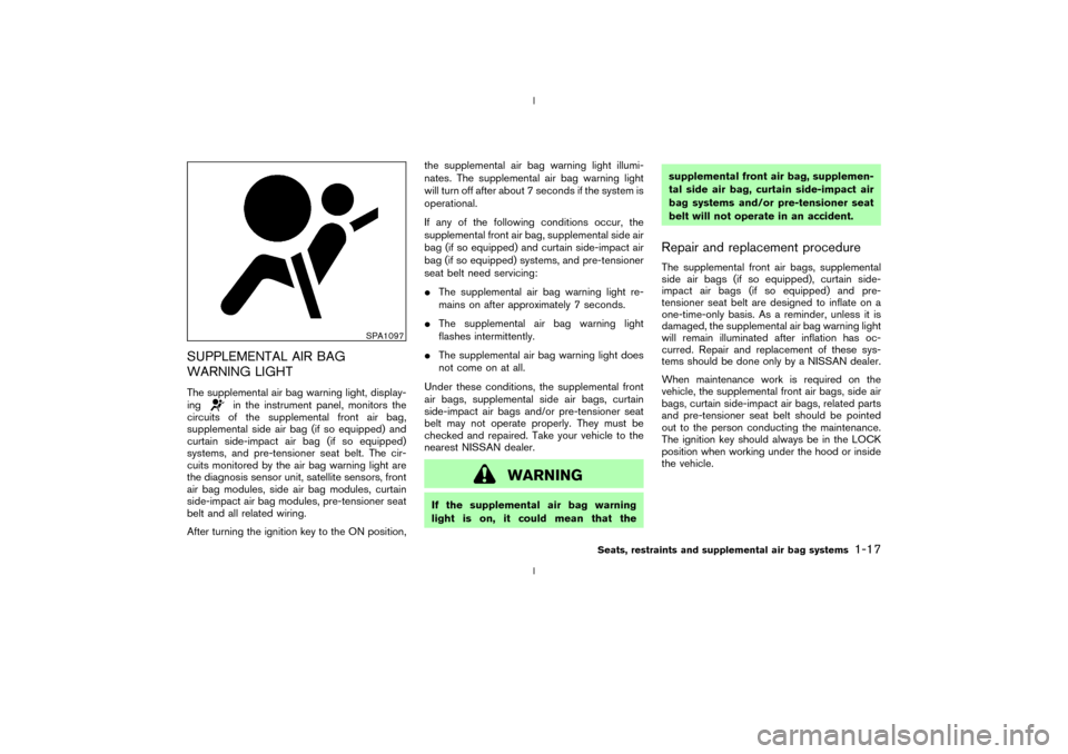
WARNING LIGHTThe supplemental air bag warning light, display-
ing
in the instrument panel, monitors the
circuits of the supplemental front air bag,
supplemental side air bag (if so equipped) and
curtain side-impact air bag (if so equipped)
systems, and pre-tensioner seat belt. The cir-
cuits monitored by the air bag warning light are
the diagnosis sensor unit, satellite sensors, front
air bag modules, side air bag modules, curtain
side-impact air bag modules, pre-tensioner seat
belt and all related wiring.
After turning the ignition key to the ON position,the supplemental air bag warning light illumi-
nates. The supplemental air bag warning light
will turn off after about 7 seconds if the system is
operational.
If any of the following conditions occur, the
supplemental front air bag, supplemental side air
bag (if so equipped) and curtain side-impact air
bag (if so equipped) systems, and pre-tensioner
seat belt need servicing:
IThe supplemental air bag warning light re-
mains on after approximately 7 seconds.
IThe supplemental air bag warning light
flashes intermittently.
IThe supplemental air bag warning light does
not come on at all.
Under these conditions, the supplemental front
air bags, supplemental side air bags, curtain
side-impact air bags and/or pre-tensioner seat
belt may not operate properly. They must be
checked and repaired. Take your vehicle to the
nearest NISSAN dealer.
WARNING
If the supplemental air bag warning
light is on, it could mean that thesupplemental front air bag, supplemen-
tal side air bag, curtain side-impact air
bag systems and/or pre-tensioner seat
belt will not operate in an accident.
Repair and replacement procedureThe supplemental front air bags, supplemental
side air bags (if so equipped), curtain side-
impact air bags (if so equipped) and pre-
tensioner seat belt are designed to inflate on a
one-time-only basis. As a reminder, unless it is
damaged, the supplemental air bag warning light
will remain illuminated after inflation has oc-
curred. Repair and replacement of these sys-
tems should be done only by a NISSAN dealer.
When maintenance work is required on the
vehicle, the supplemental front air bags, side air
bags, curtain side-impact air bags, related parts
and pre-tensioner seat belt should be pointed
out to the person conducting the maintenance.
The ignition key should always be in the LOCK
position when working under the hood or inside
the vehicle.
SPA1097
Seats, restraints and supplemental air bag systems
1-17
Z
02.9.13/Z33-D/V5.0
X
Page 43 of 227

Triple meter:
1. Trip computer
2. Engine oil pressure gauge
3. Volt meter
SPEEDOMETER AND ODOMETER
SpeedometerThe speedometer indicates vehicle speed.Odometer/Twin trip odometerThe odometer/twin trip odometer are displayed
when the ignition key is in the ON position.
The odometer records the total distance the
vehicle has been driven.
The twin trip odometer records the distance of
individual trips.Changing the display:
Pushing the reset knob changes the display as
follows:
TRIP A®TRIP B®TRIP A
Resetting the trip odometer:
Pushing the reset knob for more than 1 second
resets the trip odometer to zero.
SIC1948
SIC1949
2-4
Instruments and controls
Z
02.9.13/Z33-D/V5.0
X
Page 47 of 227

TRIP COMPUTERThe display of the trip computer is situated in the
triple meter. When the ignition switch is turned
to ON, the display scrolls all the modes of the
trip computer and then shows the mode chosen
before the ignition switch is turned OFF.Switches for the trip computer are located on
the side of the combination meter panel. To
operate the trip computer, press the side of the
switches as shown above.
qA: Trip computer mode switch
qB: Trip computer setting switch
When the ignition switch is turned to ON, modes
of the trip computer can be selected by pressing
the trip computer mode switch
qA.
Each time the mode switch
qA
is pressed, the
display will change as follows:
Speed indicator®Outside air temperature
(ICY)®Distance to empty (dte)®Average fuelconsumption and speed®Elapsed time and
trip odometer®Stopwatch®Tire pressure
indicator (PSI) (if so equipped)®Up-shift indi-
cator setting (for M/T models)®Speed indica-
tor
Speed indicator (MPH or km/h)The vehicle speed is displayed in MPH or km/h
while driving.Outside air temperature (ICY Ð ÉF or
ÉC)The outside air temperature is displayed in ÉF or
ÉC in the range of þ22 to 131ÉF (þ30 to 55ÉC).
The outside air temperature mode includes a low
temperature warning feature: below 37ÉF (3ÉC),
the outside air temperature mode is automati-
cally selected and ICY indicator will illuminate in
order to draw the driver's attention. Press the
mode switch
qAif you wish to return to the mode
that was selected before the warning occurred.
The ICY indicator will continue blinking as long
as the temperature remains below 39ÉF (4ÉC).
The ambient temperature sensor is located in
front of the radiator. The sensor may be affected
by road or engine heat, wind directions and
other driving conditions. The display may differ
from the actual ambient temperature or the
SIC1956
SIC1957
2-8
Instruments and controls
Z
02.9.13/Z33-D/V5.0
X
Page 48 of 227

temperature displayed on various signs or bill-
boards.Distance to empty (dte Ð mile or km)The distance to empty (dte) mode provides you
with an estimation of the distance that can be
driven before refueling. The dte is constantly
being calculated, based on the amount of fuel in
the fuel tank and the actual fuel consumption.
The display is updated every 30 seconds.
The dte mode includes a low range warning
feature: when the fuel level is low, the dte mode
is automatically selected and the digits blink in
order to draw the driver's attention. Press the
mode switch
qAif you wish to return to the mode
that was selected before the warning occurred.
The dte indicator will remain blinking until the
vehicle is refuelled.
When the fuel level drops even lower, the dte
display will change to (----).
NOTE:
IIf the amount of fuel added while the
ignition switch is OFF is small, the dis-
play just before the ignition switch is
turned OFF may continue to be dis-
played.
IWhen driving uphill or rounding curves,
the fuel in the tank shifts, which maymomentarily change the display.
Average fuel consumption
(Mpg or l/100 km)The average fuel consumption mode shows the
average fuel consumption since the last reset.
Resetting is done by pressing the trip computer
setting switch
qB
for more than approximately 1
second. (The average speed is also reset at the
same time.)
The display is updated every 30 seconds. At
about the first 1/3 miles (500 m) after a reset,
the display shows (----).
Average speed (MPH or km/h)The average speed mode shows the average
vehicle speed since the last reset. Resetting is
done by pressing the setting switch
qB
for more
than approximately 1 second. (The average fuel
consumption is also reset at the same time.)
The display is updated every 30 seconds. The
first 30 seconds after a reset, the display shows
(----).
Elapsed time (h:m:s)The elapsed time mode shows the time since the
last reset. The displayed time can be reset by
pressing the trip computer setting switch
qB
for
more than approximately 1 second. (The tripodometer is also reset at the same time.)
Trip odometer (MLS or km)The trip odometer mode shows the total dis-
tance the vehicle has been driven since the last
reset. Resetting is done by pressing the setting
switch
qBfor more than approximately 1 second.
(The elapsed time is also reset at the same time.)
Stopwatch (h:m:s)You can use the trip computer as a stopwatch.
Each time the trip computer setting switch
qB
is
pressed, the stopwatch will be operated as
follows:
After 100 hours, the time will start from the reset
display again.
Even if the display is switched to the other mode
while the time is starting, the stopwatch contin-
ues to advance until you stop the time in the
stopwatch mode. When the ignition switch is
turned OFF, the time is reset.Tire pressure indicator (PSI) (if so
equipped)The tire pressure indicator shows tire pressure
(0 - 51 psi) of all wheels (except the spare tire)
Instruments and controls
2-9
Z
02.9.13/Z33-D/V5.0
X
Page 49 of 227
by sending a signal from a sensor that is installed
in each wheel. Press the trip computer setting
switch
qBto change the display to F (front) or R
(rear).
The tire pressure sensor will activate only when
the vehicle is driven at speeds above 20 MPH
(32 km/h). If the tire pressure signal cannot be
received correctly, the display shows (----).
The tire pressure indicator mode includes a low
tire pressure warning feature. If the vehicle is
being driven with very low tire pressure or a flat
tire, the tire pressure indicator mode is automati-
cally selected and the PSI indicator will blink in
order to attract the driver's attention. Press the
trip computer mode switch
qA
if you wish to
return to the mode that was selected before the
warning occurred. The PSI indicator will con-
tinue blinking until the tire pressure of each tire is
properly adjusted.
For additional information, see ªLow tire pres-
sure warning systemº in the ª5. Starting and
drivingº section and ªFlat tireº in the ª6. In case
of emergencyº section.
Tire pressure shown in the display may rise
or fall while driving depending on the driv-
ing conditions (heat, etc.) and/or the out-
side temperature. This does not indicate a
system malfunction.
WARNING
The low tire pressure warning system is
not a substitute for the regular tire pres-
sure check. Be sure to check the tire
pressure regularly and adjust it to the
COLD tire pressure shown in the tire
placard.Up-shift indicator setting (rpm) (for
manual transmission models)The up-shift indicator setting mode is used to
set the desired engine speed (rpm) for the
up-shift indicator (situated in the tachometer) to
illuminate. When the engine speed approaches
or reaches the set figure, the up-shift indicator
will flash or illuminate to show the driver the
timing for shifting into a higher gear. See ªDriving
the vehicleº in the ª5. Starting and drivingº
section for the use of the up-shift indicator.
When the up-shift indicator setting mode is
selected, the rpm indicator blinks and the engine
speed currently set is displayed. (The initial
factory setting is 6,600 rpm.) The figure can be
changed between 2,000 and 8,000 rpm by
pressing trip computer setting switch
qB. Press-
ing the switch for less than approximately 1second will add the figure by 100 rpm. If press-
ing for more than approximately 1 second, the
figure will increase by 500 rpm.
If the battery cable is disconnected, the set
engine speed will be returned to the initial figure
(6,600 rpm).
Display priorityIf a low outside air temperature warning,
low dte (distance to empty) range warning
and low tire pressure warning occur simul-
taneously, other display modes switch au-
tomatically to the outside air temperature
display.
When trip computer mode switch
qA
is
pressed, the display switches to the mode
chosen before the warning display, but the
ICY indicator will continue blinking.
2-10
Instruments and controls
Z
02.9.13/Z33-D/V5.0
X
Page 52 of 227
immediatelyand call a NISSAN dealer or other
authorized repair shop.
The engine oil pressure warning light is not
designed to indicate a low oil level. Use the
dipstick to check the oil level.See ªEngine
oilº in the ª8. Maintenance and do-it-yourselfº
section.
CAUTION
Running the engine with the engine oil
pressure warning light on could cause
serious damage to the engine almost
immediately. Turn off the engine as
soon as it is safe to do so.
Low tire pressure warning light
(if so equipped)
The light comes on for about 1 second when the
key switch is turned ON, and then it turns off.
If the vehicle is being driven with a flat tire or
extremely low tire pressure, the light will illumi-
nate. Also a chime will sound for about 10
seconds if a tire is flat.
For additional information, see ªLow tire pres-
sure warning systemº in the ª5. Starting and
drivingº section and ªFlat tireº in the ª6. In caseof emergencyº section. Also, you can check the
tire pressure of all 4 tires on the trip computer
display. See ªTrip computerº earlier in this sec-
tion.
WARNING
IIf the light does not come on with the
key switch turned ON, have the ve-
hicle checked by a NISSAN dealer as
soon as possible.
IIf the light comes on while driving,
avoid sudden steering maneuvers or
abrupt braking, reduce vehicle speed,
pull off the road to a safe location
and stop the vehicle as soon as pos-
sible. Serious vehicle damage could
occur and may lead to an accident
and could result in serious personal
injury. Check the pressure for all four
tires and adjust the pressure to the
COLD tire pressure shown on the tire
placard. If the light still comes on
while driving after adjusting the tire
pressure, a tire may be flat. If you
have a flat tire, replace it with a spare
tire as soon as possible.IWhen a spare tire is mounted or a
wheel is replaced, tire pressure will
not be indicated and the low tire
pressure warning system will not
function. Contact your NISSAN
dealer as soon as possible for tire
replacement and/or system reset-
ting.
CAUTION
IThe low tire pressure warning is not a
substitute for the regular tire pres-
sure check. Be sure to check the tire
pressure regularly.
IIf the vehicle is being driven at
speeds of less than 20 MPH (32
km/h), the low tire pressure warning
system may not operate correctly.
IBe sure to install the specified size
for the front and rear tires.
Low washer fluid warning light
This light comes on when the washer tank fluid is
Instruments and controls
2-13
Z
02.9.13/Z33-D/V5.0
X
Page 66 of 227
The digital clock (in the audio unit) displays time
when the ignition key is in the ACC or ON
position.
If the power supply is disconnected, the
clock will not indicate the correct time.
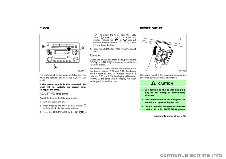
Readjust the time.ADJUSTING THE TIMEAdjust the time in the following steps:
1. Turn the audio unit on.
2. Keep pressing the DISP (Clock) button
qA
until the clock display starts to flash.
3. Press the SEEK/TRACK button
qB
(
/
) to adjust the hour. Press the TUNE
buttonqC
(
,
) to adjust the
minute. Pressing theor
side will
advance the time and the
or
side
will turn back the time.
4. Press the DISP button
qAto finish the adjust-
ment.
ResettingDuring the clock adjustment mode, pressing the
DISP
qAand TUNE
qCbuttons will reset the time
to a time signal.
For example, if these buttons are pressed while
the time is between 8:00 and 8:29, the display
will be reset to 8:00. If pressed while it is
between 8:30 and 8:59, the display will be reset
to 9:00. At the same time the display will return
to the previous audio mode.The power outlet is for powering electrical ac-
cessories such as cellular telephones.
CAUTION
IUse caution as the socket and plug
may be hot during or immediately
after use.
IThis power outlet is not designed for
use with a cigarette lighter unit.
IDo not use with accessories that ex-
ceed a 12 volt, 120W (10A) power
SIC1981
SIC1968
CLOCKPOWER OUTLET
Instruments and controls
2-27
Z
02.9.13/Z33-D/V5.0
X
Page 100 of 227
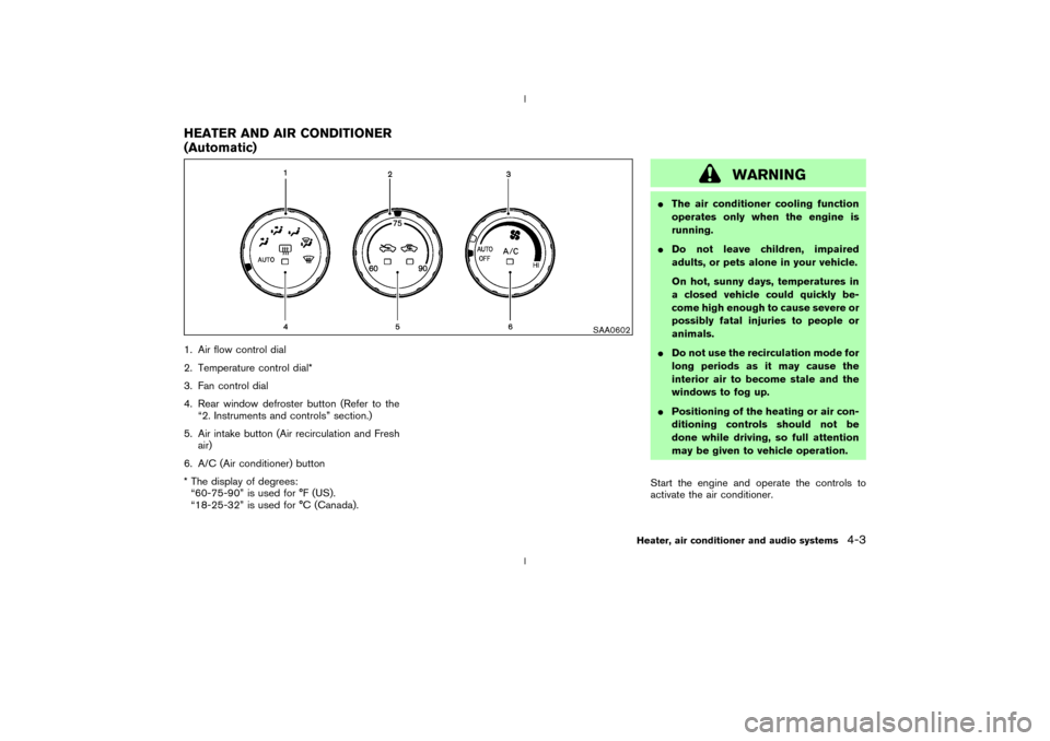
1. Air flow control dial
2. Temperature control dial*
3. Fan control dial
4. Rear window defroster button (Refer to the
ª2. Instruments and controlsº section.)
5. Air intake button (Air recirculation and Fresh
air)
6. A/C (Air conditioner) button
* The display of degrees:
ª60-75-90º is used for ÉF (US).
ª18-25-32º is used for ÉC (Canada).
WARNING
IThe air conditioner cooling function
operates only when the engine is
running.
IDo not leave children, impaired
adults, or pets alone in your vehicle.
On hot, sunny days, temperatures in
a closed vehicle could quickly be-
come high enough to cause severe or
possibly fatal injuries to people or
animals.
IDo not use the recirculation mode for
long periods as it may cause the
interior air to become stale and the
windows to fog up.
IPositioning of the heating or air con-
ditioning controls should not be
done while driving, so full attention
may be given to vehicle operation.
Start the engine and operate the controls to
activate the air conditioner.
SAA0602
HEATER AND AIR CONDITIONER
(Automatic)
Heater, air conditioner and audio systems
4-3
Z
02.9.13/Z33-D/V5.0
X