2003 NISSAN 350Z Engine light on
[x] Cancel search: Engine light onPage 76 of 227
WARNING
IDo not use the HomeLink
Universal
Transceiver with any garage door
opener that lacks safety stop and
reverse features as required by fed-
eral safety standards. (These stan-
dards became effective for opener
models manufactured after April 1,
1982). A garage door opener which
cannot detect an object in the path of
a closing garage door and then auto-
matically stop and reverse, does not
meet current federal safety stan-
dards. Using a garage door opener
without these features increases the
risk of serious injury or death.
IDuring programming, your garage
door or gate may open or close.
Make sure that people and objects
are clear of the garage door or gate
that you are programming.
IYour vehicle's engine should be
turned off while programming the
HomeLink
Universal Transceiver.
PROGRAMMING HomeLinkTo program your HomeLink Transceiver to oper-
ate a garage door, gate, or entry door opener,
home or office lighting, you need to be at the
same location as the device. Note: Garage door
openers (manufactured after 1996) have ªrolling
code protectionº. To program a garage door
opener equipped with ªrolling code protectionº;
you will need to use a ladder to get up to the
garage door opener motor to be able to access
the ªsmart or learnº program button.
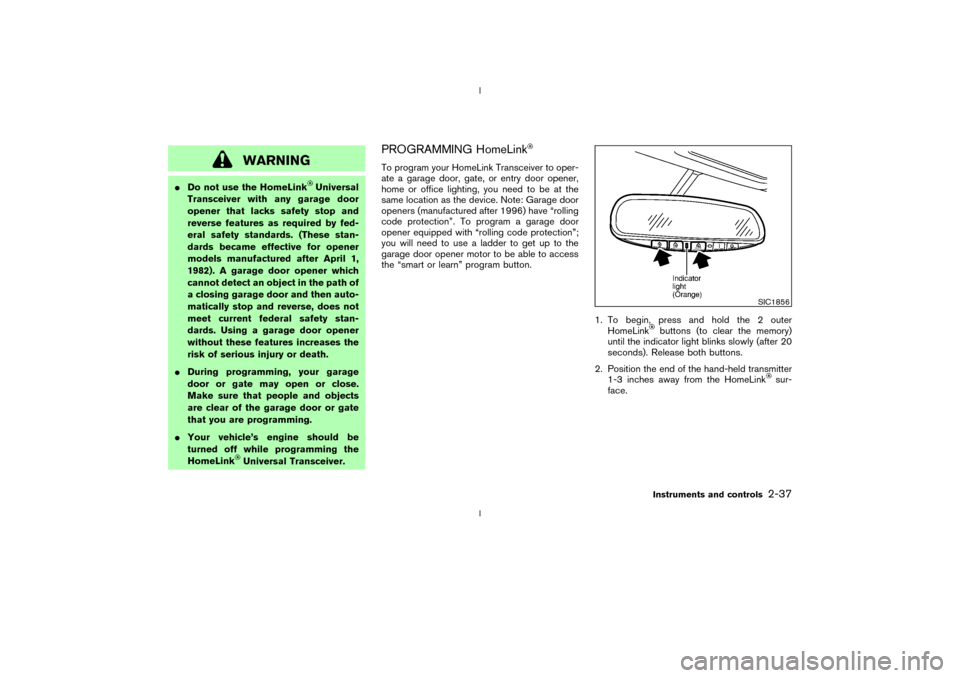
1. To begin, press and hold the 2 outer
HomeLink
buttons (to clear the memory)
until the indicator light blinks slowly (after 20
seconds). Release both buttons.
2. Position the end of the hand-held transmitter
1-3 inches away from the HomeLink
sur-
face.
SIC1856
Instruments and controls
2-37
Z
02.9.13/Z33-D/V5.0
X
Page 89 of 227
could void the user's authority to operate
the equipment. This device complies with
Part 15 of the FCC Rules and RSS-210 of
Industry Canada. Operation is subject to
the following two conditions: (1) This de-
vice may not cause harmful interference,
and (2) this device must accept any inter-
ference received, including interference
that may cause undesired operation of the
device.
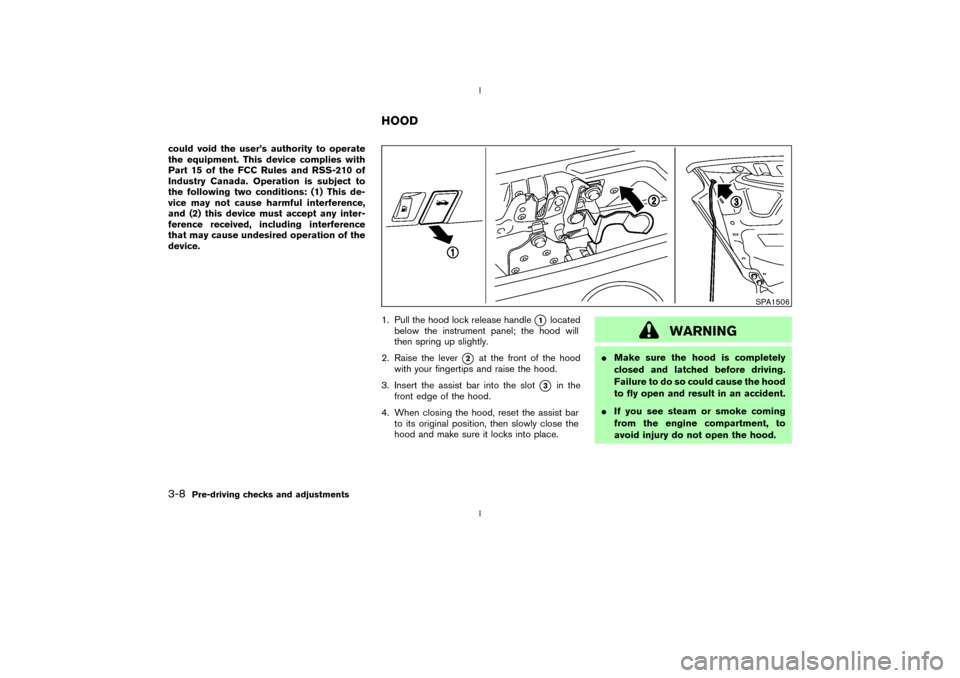
1. Pull the hood lock release handle
q1
located
below the instrument panel; the hood will
then spring up slightly.
2. Raise the lever
q2
at the front of the hood
with your fingertips and raise the hood.
3. Insert the assist bar into the slot
q3
in the
front edge of the hood.
4. When closing the hood, reset the assist bar
to its original position, then slowly close the
hood and make sure it locks into place.
WARNING
IMake sure the hood is completely
closed and latched before driving.
Failure to do so could cause the hood
to fly open and result in an accident.
IIf you see steam or smoke coming
from the engine compartment, to
avoid injury do not open the hood.
SPA1506
HOOD
3-8
Pre-driving checks and adjustments
Z
02.9.13/Z33-D/V5.0
X
Page 102 of 227

(
and
) will flash twice, and then
the intake air will be controlled automatically.
During this AUTO mode, the indicator light of
the currently selected mode illuminates.
IWhen the air flow control dial is in the
or
position, the air recirculation
mode does not activate.
Air flow controlTurning the air flow control dial selects the air
outlet to:
: Air flows from center and side ventila-
tors.: Air flows from center and side ventila-
tors and foot outlets.: Air flows mainly from foot outlets.: Air flows from defroster and foot out-
lets.: Air flows mainly from defroster outlets.
To turn the system offTurn the fan control dial to the OFF position.OPERATING TIPSWhen the engine coolant temperature and out-
side air temperature are low, the air flow from the
foot outlets may not operate for a maximum of150 seconds. However, this is not a malfunction.
After the coolant temperature warms up, the air
flow from the foot outlets will operate normally.
Sensor
qA
on the instrument panel helps main-
tain a constant temperature; do not put anything
on or around this sensor.
SAA0603
Heater, air conditioner and audio systems
4-5
Z
02.9.13/Z33-D/V5.0
X
Page 120 of 227
d. You have had an accident involv-
ing damage to the exhaust system,
underbody, or rear of the vehicle.
THREE WAY CATALYSTThe three way catalyst is an emission control
device installed in the exhaust system. Exhaust
gases in the converter are burned at high tem-
peratures to help reduce pollutants.
WARNING
IThe exhaust gas and the exhaust sys-
tem are very hot. Keep people, ani-
mals or flammable materials away
from the exhaust system compo-
nents.
IDo not stop or park the vehicle over
flammable materials such as dry
grass, waste paper or rags. They may
ignite and cause a fire.
CAUTION
IDo not use leaded gasoline. Deposits
from leaded gasoline seriously re-
duce the three way catalyst's ability
to help reduce exhaust pollutants.
IKeep your engine tuned up. Malfunc-
tions in the ignition, fuel injection, or
electrical systems can cause overrich
fuel flow into the three way catalyst,
causing it to overheat. Do not keep
driving if the engine misfires, or if
noticeable loss of performance or
other unusual operating conditions
are detected. Have the vehicle in-
spected promptly by a NISSAN
dealer.
IAvoid driving with an extremely low
fuel level. Running out of fuel could
cause the engine to misfire, damag-
ing the three way catalyst.
IDo not race the engine while warm-
ing it up.
IDo not push or tow your vehicle to
start the engine.
LOW TIRE PRESSURE WARNING
SYSTEM (if so equipped)The low tire pressure warning system displays
pressure of all tires (except the spare tire) on the
trip computer by sending a signal from a sensor
that is installed in each wheel.
The low tire pressure warning system will acti-
vate only when the vehicle is driven at speeds
above 20 MPH (32 km/h). Also, this system may
not detect a sudden drop in tire pressure (for
example, a flat tire by catching something while
driving).
Frequently check the tire pressure indicator on
the trip computer and adjust pressure of each
tire properly. See ªTrip computerº in the ª2.
Instruments and controlsº section for the tire
pressure indicator.Flat tire warningIf the vehicle is being driven with a flat tire or
extremely low tire pressure (lower than 28 psi),
the low tire pressure warning light comes on,
and the chime sounds for about 10 seconds. On
the trip computer, the PSI indicator starts flash-
ing and the current display switches to the tire
pressure indicator.
For additional information regarding the above
warning, see ªTrip computerº and
Starting and driving
5-3
Z
02.9.13/Z33-D/V5.0
X
Page 124 of 227
the LOCK position. Remove the key. To
unlock the steering wheel, insert the key
and turn it gently while rotating the steer-
ing wheel slightly right and left.
WARNING
Never remove or turn the key to the
LOCK position while driving. The steer-
ing wheel will lock. This may cause the
driver to lose control of the vehicle and
could result in serious vehicle damage
and/or personal injury.KEY POSITIONSThe switch includes an anti-theft steering lock
device.
LOCK (Normal parking position) (0)
The ignition key can only be removed when the
switch is in this position.
OFF (1)
The engine can be turned off without locking the
steering wheel.
The ignition lock is designed so that the key
cannot be turned to LOCK and removed until the
selector lever is moved to the P (Park) position.ACC (Accessories) (2)
This position activates electrical accessories
such as the radio when the engine is not running.
ON (Normal operating position) (3)
This position turns on the ignition system and the
electrical accessories.
START (4)
This position activates the starter motor, starting
the engine.
NISSAN VEHICLE IMMOBILIZER
SYSTEM (NVIS)The Nissan Vehicle Immobilizer System will not
allow the engine to start without the use of the
registered Nissan Vehicle Immobilizer System
key.
If the engine fails to start using the registered
Nissan Vehicle Immobilizer System key, it may be
due to interference caused by another Nissan
Vehicle Immobilizer System key, an automated
toll road device or automated payment device on
the key ring. Restart the engine using the follow-
ing procedures:
1. Leave the ignition switch in the ON position
for approximately 5 seconds.
2. Turn the ignition switch to the OFF or LOCKposition and wait approximately 10 seconds.
3. Repeat step 1 and 2 again.
4. Restart the engine while holding the device
(which may have caused the interference)
separate from the registered Nissan Vehicle
Immobilizer System key.
If this procedure allows the engine to start,
NISSAN recommends placing the registered
Nissan Vehicle Immobilizer System key on a
separate key ring to avoid interference from
other devices.
Starting and driving
5-7
Z
02.9.13/Z33-D/V5.0
X
Page 125 of 227
IMake sure the area around the vehicle is
clear.
IMaintenance items should be checked peri-
odically, for example, each time you check
engine oil.
ICheck that all windows and lights are clean.
IVisually inspect tires for their appearance and
condition. Also, check tires for proper infla-
tion.
ILock all doors.
IPosition seat and adjust head restraints.
IAdjust inside and outside mirrors.
IFasten seat belts and ask all passengers to
do likewise.
ICheck the operation of warning lights when
key is turned to the ON (3) position.1. Apply the parking brake.
2.Automatic transmission:
Move the selector lever to P (Park) or N
(Neutral). (P preferred.)
The starter is designed not to operate if the
selector lever is in one of the driving posi-
tions.
Manual transmission:
Move the shift lever to N (Neutral) position,
and depress the clutch pedal to the floor
while cranking the engine.
The starter is designed not to operate unless
the clutch pedal is fully depressed.
3. Crank the enginewith your foot off the
accelerator pedalby turning the ignition
key to START. Release the key when the
engine starts. If the engine starts, but fails to
run, repeat the above procedure.
IWhen the engine is very hard to start in
extremely cold weather or when restarting,
depress the accelerator pedal a little (ap-
proximately 1/5 to the floor) and hold it then
crank the engine. Release the key and the
accelerator pedal when the engine starts.
IWhen the engine is very hard to start be-
cause it is flooded, depress the acceleratorpedal all the way to the floor and hold it.
Crank the engine for 5 to 6 seconds. After
cranking the engine, release the accelerator
pedal. Crank the enginewith your foot off
the accelerator pedalby turning the igni-
tion key to START. Release the key when the
engine starts. If the engine starts, but fails to
run, repeat the above procedure.
CAUTION
Do not operate the starter for more than
15 seconds at a time. If the engine does
not start, turn the key off and wait 10
seconds before cranking again, other-
wise the starter could be damaged.
4.Warm-up
Allow the engine to idle for at least 30
seconds after starting. Drive at moderate
speed for a short distance first, especially in
cold weather.
BEFORE STARTING THE ENGINE STARTING THE ENGINE5-8
Starting and driving
Z
02.9.13/Z33-D/V5.0
X
Page 128 of 227

shift mode. Shift range can be selected manu-
ally.
In the manual shift mode, the shift range is
displayed on the position indicator in the meter.
Shift ranges up or down one by one as follows:M1®
¬
M2®
¬
M3®
¬
M4®
¬
M5
M5 (5th):
Use this position for all normal forward driving.M4 (4th):
For driving up or down long slopes where engine
braking would be advantageous.M3 (3rd) and
M2 (2nd):
Use for hill climbing or engine braking on down-
hill grades.
M1 (1st):
Use this position when climbing steep hills
slowly or driving slowly through deep snow,
sand or mud, or for maximum engine braking on
steep downhill grades.
IRemember not to drive at high speeds for
extended periods of time in lower than
M4
range. This reduces the fuel economy.
IWhen shifting up, move the selector lever to
the + (up) side. (Shifts to higher range.)IWhen shifting down, move the selector lever
to the þ (down) side. (Shifts to lower range.)
IMoving the selector lever to the same side
twice will shift the ranges in succession.
However, if this motion is rapidly done, the
second shifting may not be completed prop-
erly.
IIn the manual shift mode, the transmis-
sion automatically shifts down to 1st
gear before the vehicle comes to a stop.
When accelerating again, it is necessary
to shift up to the desired range.
IWhen canceling the manual shift mode, re-
turn the selector lever to the D position. The
transmission returns to the normal driving
mode.
IIn the manual shift mode, the transmis-
sion may not shift to the selected gear.
This helps maintain driving performance
and reduces the chance of vehicle dam-
age or loss of control.
Accelerator downshift
Ð In D position ÐFor passing or hill climbing, fully depress the
accelerator pedal to the floor. This shifts the
transmission down into the lower gear, depend-
ing on the vehicle speed.
Fail-safeWhen the fail-safe operation occurs, the next
time the key is turned to the ON position, the
warning light will blink for approximately 8
seconds after coming on for 2 seconds. While
the vehicle can be driven under these circum-
stances please note that the gears in the auto-
matic transmission will be locked in 4th gear.
If the vehicle is driven under extreme con-
ditions, such as excessive wheel spinning
and subsequent hard braking, the fail-safe
system may be activated. This will occur
even if all electrical circuits are functioning
properly. In this case, turn the ignition key
OFF and wait for 3 seconds. Then turn the
key back to the ON position. The vehicle
should return to its normal operating con-
dition. If it does not return to its normal
operating condition, have your NISSAN
dealer check the transmission and repair if
necessary.
Starting and driving
5-11
Z
02.9.13/Z33-D/V5.0
X
Page 130 of 227
light, shift to N (Neutral) and release
the clutch pedal with the foot brake
applied.
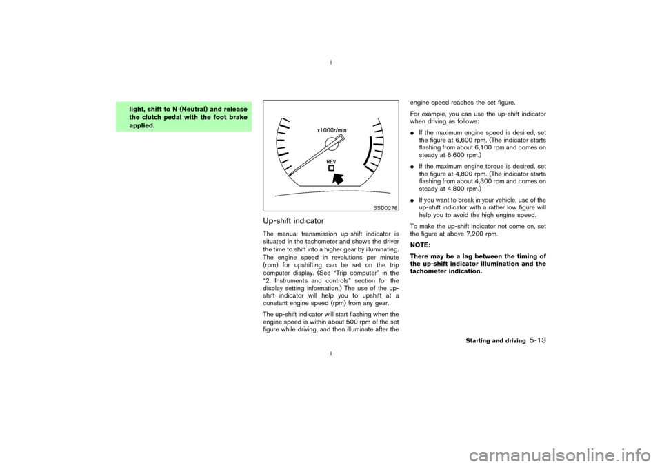
Up-shift indicatorThe manual transmission up-shift indicator is
situated in the tachometer and shows the driver
the time to shift into a higher gear by illuminating.
The engine speed in revolutions per minute
(rpm) for upshifting can be set on the trip
computer display. (See ªTrip computerº in the
ª2. Instruments and controlsº section for the
display setting information.) The use of the up-
shift indicator will help you to upshift at a
constant engine speed (rpm) from any gear.
The up-shift indicator will start flashing when the
engine speed is within about 500 rpm of the set
figure while driving, and then illuminate after theengine speed reaches the set figure.
For example, you can use the up-shift indicator
when driving as follows:
IIf the maximum engine speed is desired, set
the figure at 6,600 rpm. (The indicator starts
flashing from about 6,100 rpm and comes on
steady at 6,600 rpm.)
IIf the maximum engine torque is desired, set
the figure at 4,800 rpm. (The indicator starts
flashing from about 4,300 rpm and comes on
steady at 4,800 rpm.)
IIf you want to break in your vehicle, use of the
up-shift indicator with a rather low figure will
help you to avoid the high engine speed.
To make the up-shift indicator not come on, set
the figure at above 7,200 rpm.
NOTE:
There may be a lag between the timing of
the up-shift indicator illumination and the
tachometer indication.
SSD0278
Starting and driving
5-13
Z
02.9.13/Z33-D/V5.0
X