Page 17 of 4500
Courtesy of TOYOTA MOTOR SALES, U.S.A., INC.
1.CHECK FOR INTERMITTENT PROBLEMS
HINT:
A momentary interruption (open circuit) in the connectors and/or wire harness between the sensors and ECUs
can be detected in the ECU data monitor function of the hand-held tester.
a. Turn the ignition switch off and connect the hand-held tester to the DLC3.
b. Turn the ignition switch on. Follow the on-screen directions on the hand-held tester to display the DATA
LIST and select areas where momentary interruption should be monitored.
HINT:
A momentary interruption (open circuit) cannot be detected for 3 seconds after the ignition switch is
turned on (initial check).
Page 21 of 4500
clearing and reading the sensor calibration data are necessary.
b. Follow the chart to perform calibration.
Fig. 14: VSC Relevant Components Description
Courtesy of TOYOTA MOTOR SALES, U.S.A., INC.
Fig. 15: Connecting Hand
-Held Tester To DLC3 (1 Of 2)
Courtesy of TOYOTA MOTOR SALES, U.S.A., INC.
2.CLEAR ZERO POINT CALIBRATION
a. Clearing the DTCs.
1. Connect the han
d-held tester to the DLC3.
Page 25 of 4500
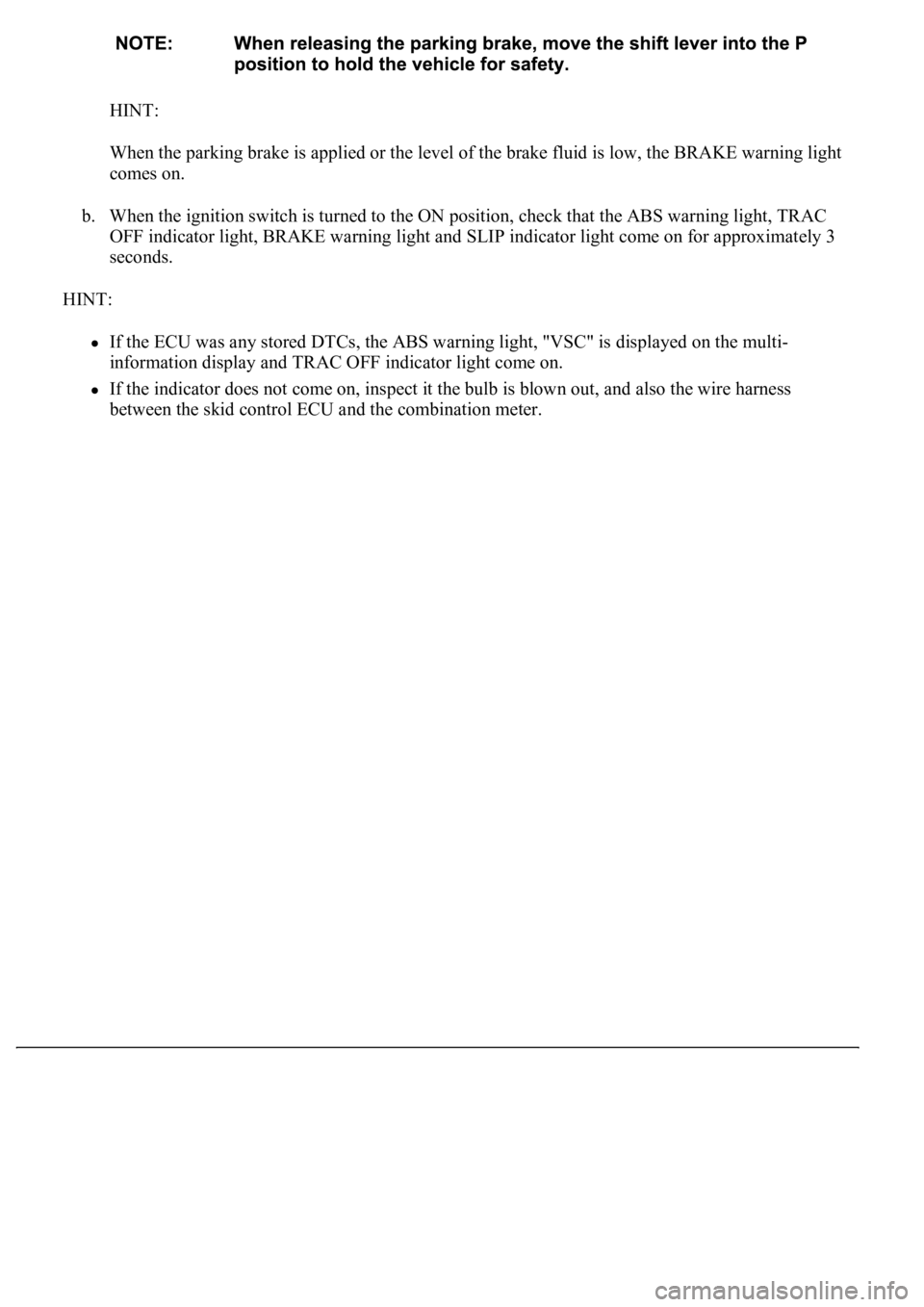
HINT:
<003a004b0048005100030057004b00480003005300440055004e004c0051004a0003004500550044004e00480003004c00560003004400530053004f004c0048004700030052005500030057004b00480003004f004800590048004f000300520049000300
57004b00480003004500550044004e004800030049004f0058[id is low, the BRAKE warning light
comes on.
b. When the ignition switch is turned to the ON position, check that the ABS warning light, TRAC
OFF indicator light, BRAKE warning light and SLIP indicator light come on for approximately 3
seconds.
HINT:
If the ECU was any stored DTCs, the ABS warning light, "VSC" is displayed on the multi-
information display and TRAC OFF indicator light come on.
If the indicator does not come on, inspect it the bulb is blown out, and also the wire harness
between the skid control ECU and the combination meter.
Page 27 of 4500
Fig. 19: Identifying VSC Location
Courtesy of TOYOTA MOTOR SALES, U.S.A., INC.
If the indicator remains on, proceed to troubleshooting for the light circuit below.
TROUBLE AREA REFERENCE
2.SENSOR SIGNAL CHECK BY TEST MODE
HINT:
If the ignition switch is turned from ON to the ACC or LOCK position during test mode, DTC of
Trouble areaSee Procedure
ABS warning light circuitABS WARNING LIGHT CIRCUIT (REMAINS ON)
BRAKE warning light circuitBRAKE WARNING LIGHT CIRCUIT
TRAC OFF indicator light
circuitTRAC OFF INDICATOR LIGHT, TRAC OFF SWITCH
CIRCUIT
SLIP indicator light circuitSLIP INDICATOR LIGHT CIRCUIT
Page 34 of 4500
2. Drive the vehicle straight forward.
Drive the vehicle at a speed of 28 to 50 mph (45 to 80 km/h) or higher for several seconds and
check that the ABS warning light goes off.
Fig. 25: Identifying ABS Warning Light Blinking Pattern
Courtesy of TOYOTA MOTOR SALES, U.S.A., INC.
VEHICLE SPEED SPECIFICATIONS
HINT:
Vehicle SpeedTestCheck
0 to 28 mph (0 to 45 km/h)Low speed testResponse of sensors
28 to 50 mph (45 to 80 km/h)Middle speed testDeviations of sensor signal
Page 37 of 4500
Fig. 27: DTC of TEST MODE CODE Description
Courtesy of TOYOTA MOTOR SALES, U.S.A., INC.
HINT:
The codes in this table are output only in TEST MODE.
If there are no DTCs output but the problem still occurs, check the circuits for each problem symptom in the
order
given in the table below and proceed to the relevant troubleshooting page.
Page 39 of 4500
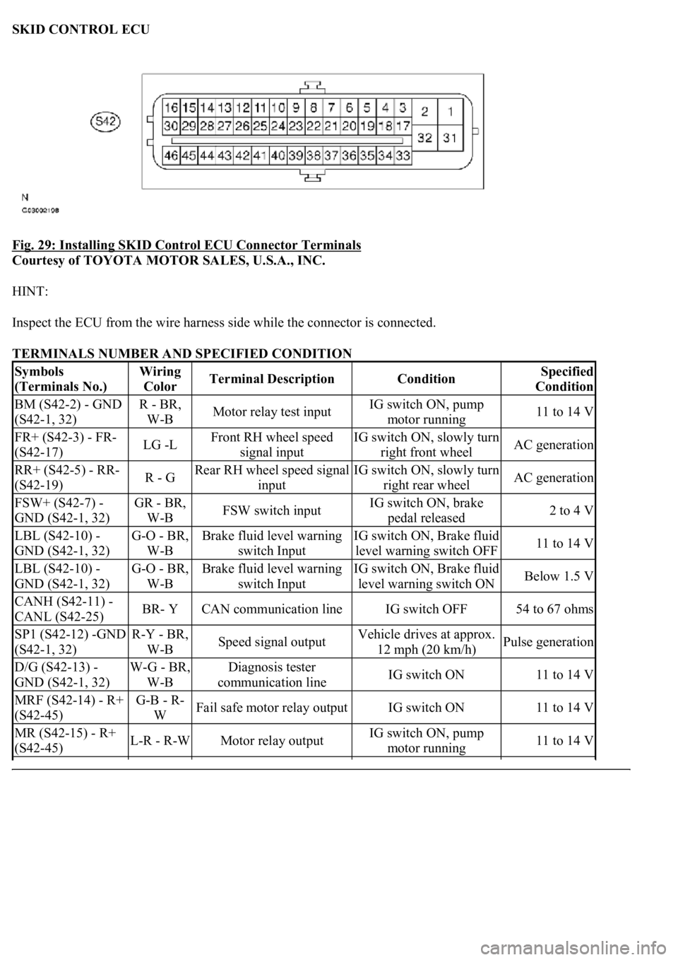
SKID CONTROL ECU
Fig. 29: Installing SKID Control ECU Connector Terminals
Courtesy of TOYOTA MOTOR SALES, U.S.A., INC.
HINT:
Inspect the ECU from the wire harness side while the connector is connected.
TERMINALS NUMBER AND SPECIFIED CONDITION
Symbols
(Terminals No.)Wiring
ColorTerminal DescriptionConditionSpecified
Condition
BM (S42-2) - GND
(S42-1, 32)R - BR,
W-BMotor relay test inputIG switch ON, pump
motor running11 to 14 V
FR+ (S42-3) - FR-
(S42-17)LG -LFront RH wheel speed
signal inputIG switch ON, slowly turn
right front wheelAC generation
RR+ (S42-5) - RR-
(S42-19)R - GRear RH wheel speed signal
inputIG switch ON, slowly turn
right rear wheelAC generation
FSW+ (S42-7) -
GND (S42-1, 32)GR - BR,
W-BFSW switch inputIG switch ON, brake
pedal released2 to 4 V
LBL (S42-10) -
GND (S42-1, 32)G-O - BR,
W-BBrake fluid level warning
switch InputIG switch ON, Brake fluid
level warning switch OFF11 to 14 V
LBL (S42-10) -
GND (S42-1, 32)G-O - BR,
W-BBrake fluid level warning
switch InputIG switch ON, Brake fluid
level warning switch ONBelow 1.5 V
CANH (S42-11) -
CANL (S42-25)BR- YCAN communication lineIG switch OFF54 to 67 ohms
SP1 (S42-12) -GND
(S42-1, 32)R-Y - BR,
W-BSpeed signal outputVehicle drives at approx.
12 mph (20 km/h)Pulse generation
D/G (S42-13) -
GND (S42-1, 32)W-G - BR,
W-BDiagnosis tester
communication lineIG switch ON11 to 14 V
MRF (S42-14) - R+
(S42-45)G-B - R-
WFail safe motor relay outputIG switch ON11 to 14 V
MR (S42-15) - R+
(S42-45)L-R - R-WMotor relay outputIG switch ON, pump
motor running11 to 14 V
Page 40 of 4500

1.DIAGNOSIS
FL+ (S42-18) - FL-
(S42-4)P -VFront LH wheel speed
signal inputIG switch ON, slowly turn
left front wheelAC generation
RL+ (S42-20) - RL-
(S42-6)BR-W -
BRRear LH wheel speed signal
inputIG switch ON, slowly turn
left rear wheelAC generation
TS (S42-24) -GND
(S42-1, 32)B - BR,
W-BSensor check inputIG switch ON11 to 14 V
STP (S42-27) -
GND (S42-1, 32)G-W - BR,
W-BStop lamp switch inputStop light switch ON
(Brake pedal pushed)8 to 14 V
STP (S42-27) -
GND (S42-1, 32)G-W - BR,
W-BStop lamp switch inputStop light switch OFF
(Brake pedal released)Below 1.5 V
PKB (S42-28) -
GND (S42-1, 32)B-L - BR,
W-BParking brake switch inputIG switch ON, parking
brake switch ONBelow 1.5 V
PKB (S42-28) -
GND (S42-1, 32)B-L - BR,
W-BParking brake switch inputIG switch ON, parking
brake switch OFF11 to 14 V
BZ (S42-30) -GND
(S42-1, 32)W-R - BR,
W-BBuzzer outputIG switch ON, VSC
buzzer soundsBelow 1.0 <-->
11 to 14 V
BZ (S42-30) -GND
(S42-1, 32)W-R - BR,
W-BBuzzer outputIG switch ON, VSC
buzzer does not sound11 to 14 V
+BS (S42-31) -
GND (S42-1, 32)B - BR,
W-BSolenoid relay power supplyAlways11 to 14 V
FRO (S42-37) -
GND (S42-1, 32)Y-R - BR,
W-BFront RH wheel speed
signal outputVehicle drives at approx.
12 mph (20 km/h)Pulse generation
FLO (S42-38) -
GND (S42-1, 32)Y-B - BR,
W-BFront LH wheel speed
signal outputVehicle drives at approx.
12 mph (20 km/h)Pulse generation
INIT (S42-41) -
GND (S42-1, 32)GR-R -
BR, W-BThe pressure warning
standardization switch InputIG switch ON, The
pressure warning switch
ON
Below 1.5 V
INIT (S42-41) -
GND (S42-1, 32)GR-R -
BR, W-BThe pressure warning
standardization switch InputIG switch ON, The
pressure warning switch
OFF
11 to 14 V
WFSE (S42-42) -
GND (S42-1, 32)LG-B -
BR, W-BWFSE inputIG switch ON11 to 14 V
CSW (S42-43) -
GND (S42-1, 32)Y-G - BR,
W-BTRAC cut switch InputIG switch ON, TRAC
OFF switch is off11 to 14 V
CSW (S42-43) -
GND (S42-1, 32)Y-G - BR,
W-BTRAC cut switch InputIG switch ON, TRAC
OFF switch is onBelow 1.5 V
R+ (S42-45) -GND
(S42-1, 32)R-W - BR,
W-BPower supply for motor
relayIG switch ON11 to 14 V
IG1 (S42-46) -GND
(S42-1, 32)B-R - BR,
W-BIG1 power supplyIG switch ON11 to 14 V