Page 2857 of 4500
Fig. 161: DTC Reference Chart
Courtesy of TOYOTA MOTOR SALES, U.S.A., INC.
MONITOR DESCRIPTION
The ECM calculates the amount of heat absorbed by the friction material based on the difference in revolution
(clutch slippage) between the turbine and output shaft. The ECM turns on the MIL and outputs this DTC when
the amount of heat absorption exceeds the specified value.
When the shift solenoid valve SLT remains on, oil pressure goes down and clutch engagement force decreases.
MONITOR STRATEGY
MONITOR STRATEGY TABLE
TYPICAL ENABLING CONDITIONS
ON malfunction
Related DTCsP2714: Shift solenoid valve SLT/ON malfunction
Required sensors/ComponentsShift solenoid valve SLT
Frequency of operationContinuous
DurationBetween starting in the 1st gear and stopping in the
4th gear
MIL operation2 driving cycles
Sequence of operationNone
Page 2863 of 4500
MONITOR STRATEGY TABLE
TYPICAL ENABLING CONDITIONS
TYPICAL ENABLING CONDITIONS TABLE
TYPICAL MALFUNCTION THRESHOLDS
TYPICAL MALFUNCTION THRESHOLDS TABLE
COMPONENT OPERATING RANGE
COMPONENT OPERATING RANGE TABLE
WIRING DIAGRAM
Related DTCsP2716: Shift solenoid valve SLT/Range check
Required sensors/ComponentsShift solenoid valve SLT
Frequency of operationContinuous
Duration1 sec.
MIL operationImmediate
Sequence of operationNone
The monitor will run whenever this DTC is not
present.See LIST OF DISABLE A MONITOR
Solenoid current cut statusNot cut
CPU command duty ratio to SLT19% or more
Battery voltage11 V or more
Ignition switchON
StarterOFF
Solenoid status (SLT) from ICFail (Open or short)
Output signal dutyLess than 100%
Page 2869 of 4500
OK: REPAIR OR REPLACE TRANSMISSION WIRE (See step 5 on REPLACEMENT)
DTC P2757: TORQUE CONVERTER CLUTCH PRESSURE CONTROL SOLENOID
PERFORMANCE (SHIFT SOLENOID VALVE SLU)
SYSTEM DESCRIPTION
The ECM uses the signals from the throttle position sensor, Air-flow meter, turbine (input) speed sensor, output
speed sensor and crankshaft position sensor to monitor the engagement condition of the lock-up clutch.
Then the ECM compares the engagement condition of the lock-up clutch with the lock-up schedule in the ECM
memory to detect a mechanical problems of the shift solenoid valve SLU, valve body and torque converter
clutch.
Fig. 173: Identifying Manual Transmission
Courtesy of TOYOTA MOTOR SALES, U.S.A., INC.
Page 2870 of 4500
Fig. 174: Identifying Lock-Up Operation Pressure Graph
Courtesy of TOYOTA MOTOR SALES, U.S.A., INC.
Fig. 175: DTC Reference Chart
Courtesy of TOYOTA MOTOR SALES, U.S.A., INC.
MONITOR DESCRIPTION
Torque converter lock-up is controlled by the ECM based on turbine (input) speed sensor NT, output speed
sensor SP2, engine rpm, engine load, engine temperature, vehicle speed, transmission temperature, and gear
selection. The ECM determines the lock-up status of the torque converter by comparing the engine rpm (NE) to
the input turbine rpm (NT). The ECM calculates the actual transmission gear by comparing input turbine rpm
(NT) to output shaft rpm (SP2). When conditions are appropriate, the ECM requests "lock-up" by applying
control volta
ge to shift solenoid SLU. When the SLU is turned on, solenoid SLU applies pressure to the lock-up
Page 2871 of 4500

relay valve and locks the torque converter clutch.
If the ECM detects no lock-up after lock-up has been requested or if it detects lock-up when it is not requested,
the ECM interprets this as a fault in the shift solenoid valve SLU or lock-up system performance.
The ECM will turn on the MIL and store the DTC.
Example:
When any of the following is met, the system judges it as a malfunction.
a. There is a difference in rotation between before and after torque converters even when the ECM
commands lock-up.
(Engine speed is at least 75 rpm greater than input turbine speed.)
b. There is no difference in rotation between before and after torque converters even when the ECM
commands lock-up off.
(The difference between engine speed and input turbine speed is less than 35 rpm.)
MONITOR STRATEGY
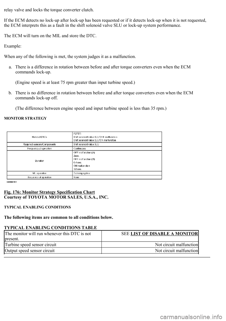
Fig. 176: Monitor Strategy Specification Chart
Courtesy of TOYOTA MOTOR SALES, U.S.A., INC.
TYPICAL ENABLING CONDITIONS
The following items are common to all conditions below.
TYPICAL ENABLING CONDITIONS TABLE
The monitor will run whenever this DTC is not
present.SEE LIST OF DISABLE A MONITOR
Turbine speed sensor circuitNot circuit malfunction
Output speed sensor circuitNot circuit malfunction
Page 2872 of 4500

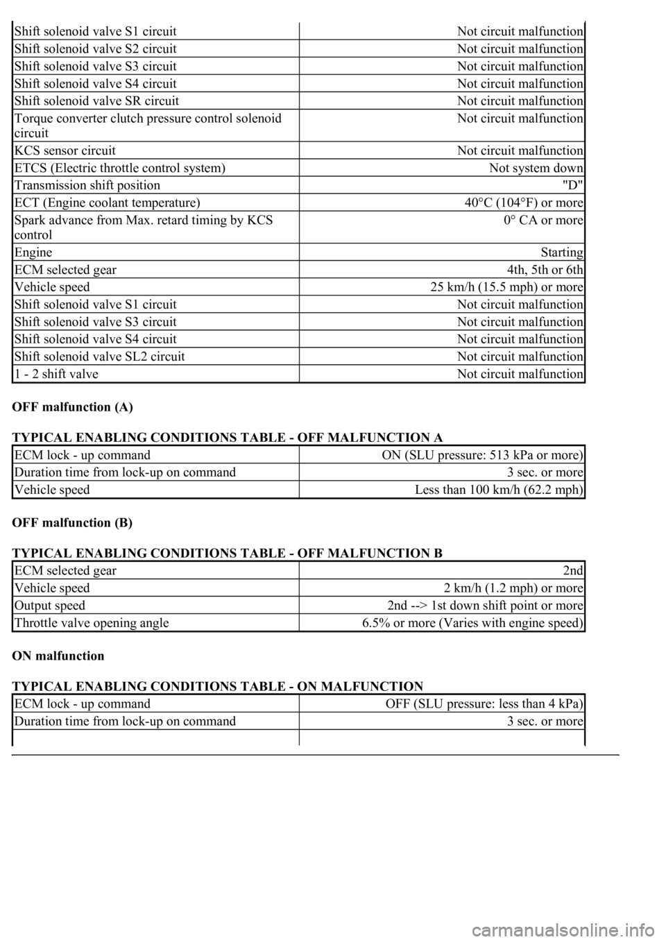
OFF malfunction (A)
TYPICAL ENABLING CONDITIONS TABLE - OFF MALFUNCTION A
OFF malfunction (B)
TYPICAL ENABLING CONDITIONS TABLE - OFF MALFUNCTION B
ON malfunction
TYPICAL ENABLING CONDITIONS TABLE - ON MALFUNCTION
Shift solenoid valve S1 circuitNot circuit malfunction
Shift solenoid valve S2 circuitNot circuit malfunction
Shift solenoid valve S3 circuitNot circuit malfunction
Shift solenoid valve S4 circuitNot circuit malfunction
Shift solenoid valve SR circuitNot circuit malfunction
Torque converter clutch pressure control solenoid
circuitNot circuit malfunction
KCS sensor circuitNot circuit malfunction
ETCS (Electric throttle control system)Not system down
Transmission shift position"D"
ECT (Engine coolant temperature)40°C (104°F) or more
Spark advance from Max. retard timing by KCS
control0° CA or more
EngineStarting
ECM selected gear4th, 5th or 6th
Vehicle speed25 km/h (15.5 mph) or more
Shift solenoid valve S1 circuitNot circuit malfunction
Shift solenoid valve S3 circuitNot circuit malfunction
Shift solenoid valve S4 circuitNot circuit malfunction
Shift solenoid valve SL2 circuitNot circuit malfunction
1 - 2 shift valveNot circuit malfunction
ECM lock - up commandON (SLU pressure: 513 kPa or more)
Duration time from lock-up on command3 sec. or more
Vehicle speedLess than 100 km/h (62.2 mph)
ECM selected gear2nd
Vehicle speed2 km/h (1.2 mph) or more
Output speed2nd --> 1st down shift point or more
Throttle valve opening angle6.5% or more (Varies with engine speed)
ECM lock - up commandOFF (SLU pressure: less than 4 kPa)
Duration time from lock-up on command3 sec. or more
Page 2873 of 4500

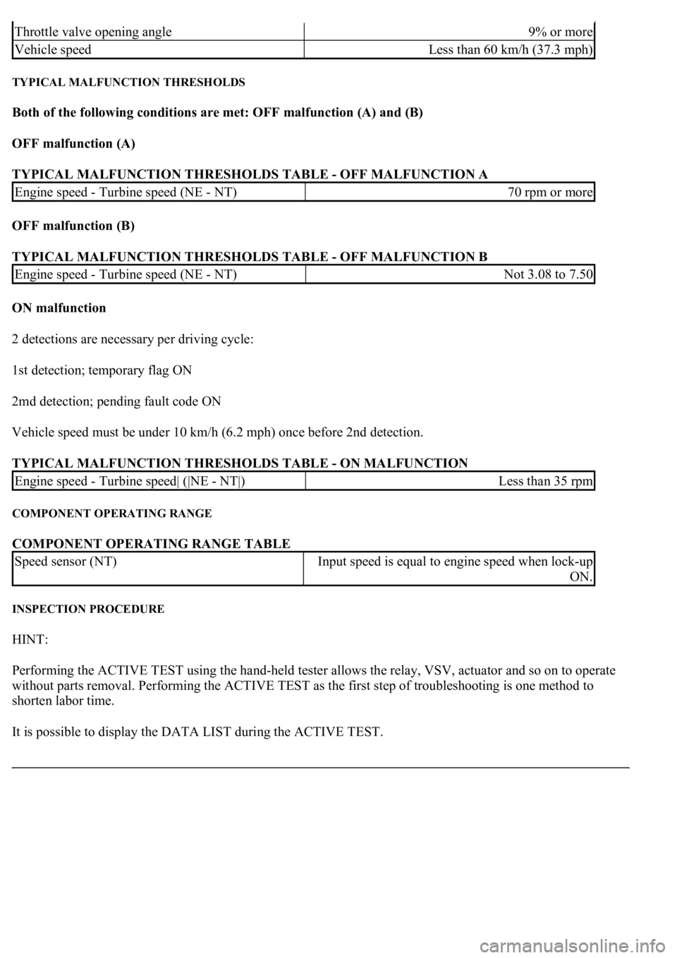
TYPICAL MALFUNCTION THRESHOLDS
Both of the following conditions are met: OFF malfunction (A) and (B)
OFF malfunction (A)
TYPICAL MALFUNCTION THRESHOLDS TABLE - OFF MALFUNCTION A
OFF malfunction (B)
TYPICAL MALFUNCTION THRESHOLDS TABLE - OFF MALFUNCTION B
ON malfunction
2 detections are necessary per driving cycle:
1st detection; temporary flag ON
2md detection; pending fault code ON
Vehicle speed must be under 10 km/h (6.2 mph) once before 2nd detection.
TYPICAL MALFUNCTION THRESHOLDS TABLE - ON MALFUNCTION
COMPONENT OPERATING RANGE
COMPONENT OPERATING RANGE TABLE
INSPECTION PROCEDURE
HINT:
Performing the ACTIVE TEST using the hand-held tester allows the relay, VSV, actuator and so on to operate
without parts removal. Performing the ACTIVE TEST as the first step of troubleshooting is one method to
shorten labor time.
It is possible to display the DATA LIST during the ACTIVE TEST.
Throttle valve opening angle9% or more
Vehicle speedLess than 60 km/h (37.3 mph)
Engine speed - Turbine speed (NE - NT)70 rpm or more
Engine speed - Turbine speed (NE - NT)Not 3.08 to 7.50
Engine speed - Turbine speed| (|NE - NT|)Less than 35 rpm
Speed sensor (NT)Input speed is equal to engine speed when lock-up
ON.
Page 2879 of 4500
Fig. 181: Identifying Duty Ratio Pattern
Courtesy of TOYOTA MOTOR SALES, U.S.A., INC.
Fig. 182: DTC Reference Chart
Courtesy of TOYOTA MOTOR SALES, U.S.A., INC.
MONITOR DESCRIPTION
When an open or short in a shift solenoid valve (SLU) circuit is detected, the ECM determines there is a
malfunction. The ECM will turn on the MIL and store this DTC.
MONITOR STRATEGY
MONITOR STRATEGY TABLE
Related DTCsP2759: Shift solenoid valve SLU/Range check
Required sensors/ComponentsShift solenoid valve SLU
Frequency of operationContinuous