Page 1756 of 4500

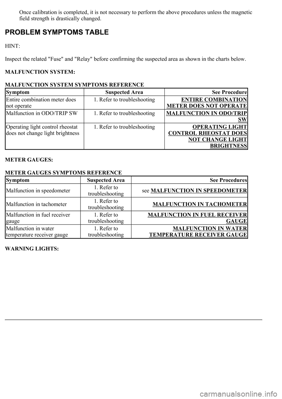
Once calibration is completed, it is not necessary to perform the above procedures unless the magnetic
field strength is drastically changed.
HINT:
Inspect the related "Fuse" and "Relay" before confirming the suspected area as shown in the charts below.
MALFUNCTION SYSTEM:
MALFUNCTION SYSTEM SYMPTOMS REFERENCE
METER GAUGES:
METER GAUGES SYMPTOMS REFERENCE
WARNING LIGHTS:
SymptomSuspected AreaSee Procedure
Entire combination meter does
not operate1. Refer to troubleshootingENTIRE COMBINATION
METER DOES NOT OPERATE
Malfunction in ODO/TRIP SW1. Refer to troubleshootingMALFUNCTION IN ODO/TRIP
SW
Operating light control rheostat
does not change light brightness1. Refer to troubleshootingOPERATING LIGHT
CONTROL RHEOSTAT DOES
NOT CHANGE LIGHT
BRIGHTNESS
SymptomSuspected AreaSee Procedures
Malfunction in speedometer1. Refer to
troubleshootingsee MALFUNCTION IN SPEEDOMETER
Malfunction in tachometer1. Refer to
troubleshootingMALFUNCTION IN TACHOMETER
Malfunction in fuel receiver
gauge1. Refer to
troubleshootingMALFUNCTION IN FUEL RECEIVER
GAUGE
Malfunction in water
temperature receiver gauge1. Refer to
troubleshootingMALFUNCTION IN WATER
TEMPERATURE RECEIVER GAUGE
Page 1859 of 4500
Fig. 8: Checking Cooling Fan System
Courtesy of TOYOTA MOTOR SALES, U.S.A., INC.
3.INSPECT COOLING FAN ECU WIRE HARNESS
a. Remove the air cleaner inlet No. 1.
b. Disconnect the 2 connectors.
c. Inspect the connector on the wire harness side.
d. Measure the voltage between terminals 1 and 3.
Standard: 9 to 14 V
If the result is not as specified, check the fuse, relay and wire harness.
If the result is as specified, replace the fan ECU.
Page 1860 of 4500
Fig. 9: Measuring Voltage Between Terminals 1 And 3.
Courtesy of TOYOTA MOTOR SALES, U.S.A., INC.
INSPECTION
1.INSPECT RELAY (Marking: FAN)
a. Remove the FAN relay from the FL block
b. Measure the resistance of the relay.
STANDARD SPECIFICATION
If the result is not as specified, replace the rela
y.
Tester ConnectionSpecified Condition
3-510 kQ or higher
3-5Below 1 Q (when battery voltage is applied to terminals 1 and 2)
Page 1861 of 4500
Fig. 10: Measuring Resistance Relay
Courtesy of TOYOTA MOTOR SALES, U.S.A., INC.
2.INSPECT ECT SWITCH
a. Measure the resistance of the switch.
STANDARD SPECIFICATION
If the result is not as specified, replace the switch.
TemperatureSpecified Condition
Above 98° C (208° F)Below 1 Q
Below 88° C (190° F)10 kQ or higher
Page 1913 of 4500
Fig. 9: Checking RES (RESUME) Function
Courtesy of TOYOTA MOTOR SALES, U.S.A., INC.
If a normal system code is displayed during the DTC check but the problem still occurs, check the circuits for
each problem symptom in the order given in the table below and proceed to the relevant troubleshooting page.
HINT:
Inspect the "Fuse" and "Relay" before confirming the suspected areas as shown in the chart below.
Inspect each malfunction circuit in numerical order for the correspondin
g symptom.
Page 1921 of 4500

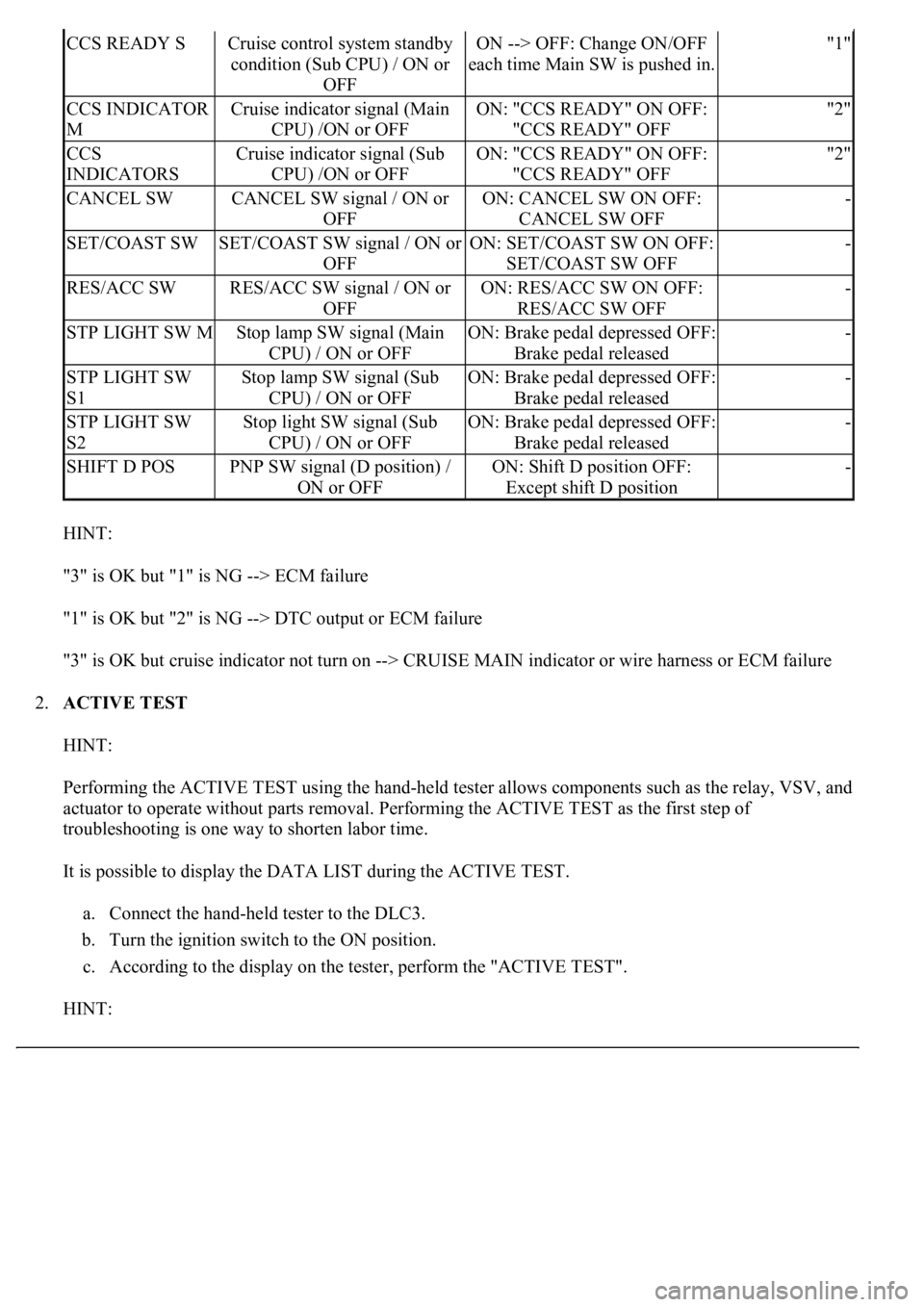
HINT:
"3" is OK but "1" is NG --> ECM failure
"1" is OK but "2" is NG --> DTC output or ECM failure
"3" is OK but cruise indicator not turn on --> CRUISE MAIN indicator or wire harness or ECM failure
2.ACTIVE TEST
HINT:
Performing the ACTIVE TEST using the hand-held tester allows components such as the relay, VSV, and
actuator to operate without parts removal. Performing the ACTIVE TEST as the first step of
troubleshooting is one way to shorten labor time.
It is possible to display the DATA LIST during the ACTIVE TEST.
a. Connect the hand-held tester to the DLC3.
b. Turn the ignition switch to the ON position.
c. According to the display on the tester, perform the "ACTIVE TEST".
HINT:
CCS READY SCruise control system standby
condition (Sub CPU) / ON or
OFFON --> OFF: Change ON/OFF
each time Main SW is pushed in."1"
CCS INDICATOR
MCruise indicator signal (Main
CPU) /ON or OFFON: "CCS READY" ON OFF:
"CCS READY" OFF"2"
CCS
INDICATORSCruise indicator signal (Sub
CPU) /ON or OFFON: "CCS READY" ON OFF:
"CCS READY" OFF"2"
CANCEL SWCANCEL SW signal / ON or
OFFON: CANCEL SW ON OFF:
CANCEL SW OFF-
SET/COAST SWSET/COAST SW signal / ON or
OFFON: SET/COAST SW ON OFF:
SET/COAST SW OFF-
RES/ACC SWRES/ACC SW signal / ON or
OFFON: RES/ACC SW ON OFF:
RES/ACC SW OFF-
STP LIGHT SW MStop lamp SW signal (Main
CPU) / ON or OFFON: Brake pedal depressed OFF:
Brake pedal released-
STP LIGHT SW
S1Stop lamp SW signal (Sub
CPU) / ON or OFFON: Brake pedal depressed OFF:
Brake pedal released-
STP LIGHT SW
S2Stop light SW signal (Sub
CPU) / ON or OFFON: Brake pedal depressed OFF:
Brake pedal released-
SHIFT D POSPNP SW signal (D position) /
ON or OFFON: Shift D position OFF:
Except shift D position-
Page 1992 of 4500

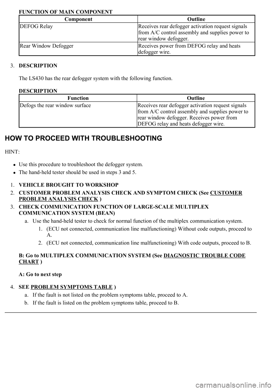
FUNCTION OF MAIN COMPONENT
3.DESCRIPTION
The LS430 has the rear defogger system with the following function.
DESCRIPTION
HINT:
<00380056004800030057004b004c00560003005300550052004600480047005800550048000300570052000300570055005200580045004f00480056004b00520052005700030057004b004800030047004800490052004a004a0048005500030056005c00
56005700480050001100030003[
<0037004b00480003004b0044005100470010004b0048004f0047000300570048005600570048005500030056004b00520058004f0047000300450048000300580056004800470003004c005100030056005700480053005600030016000300440051004700
030018001100030003[
1.VEHICLE BROUGHT TO WORKSHOP
2.CUSTOMER PROBLEM ANALYSIS CHECK AND SYMPTOM CHECK (See CUSTOMER
PROBLEM ANALYSIS CHECK )
3.CHECK COMMUNICATION FUNCTION OF LARGE-SCALE MULTIPLEX
COMMUNICATION SYSTEM (BEAN)
a. Use the hand-held tester to check for normal function of the multiplex communication system.
1. (ECU not connected, communication line malfunctioning) Without code outputs, proceed to
A.
2. (ECU not connected, communication line malfunctioning) With code outputs, proceed to B.
B: Go to MULTIPLEX COMMUNICATION SYSTEM (See DIAGNOSTIC TROUBLE CODE
CHART )
A: Go to next step
4.SEE PROBLEM SYMPTOMS TABLE
)
a. If the fault is not listed on the problem symptoms table, proceed to A.
b. If the fault is listed on the problem symptoms table, proceed to B.
ComponentOutline
DEFOG RelayReceives rear defogger activation request signals
from A/C control assembly and supplies power to
rear window defogger.
Rear Window DefoggerReceives power from DEFOG relay and heats
defogger wire.
FunctionOutline
Defogs the rear window surfaceReceives rear defogger activation request signals
from A/C control assembly and supplies power to
rear window defogger. Receives power from
DEFOG relay and heats defogger wire.
Page 1995 of 4500

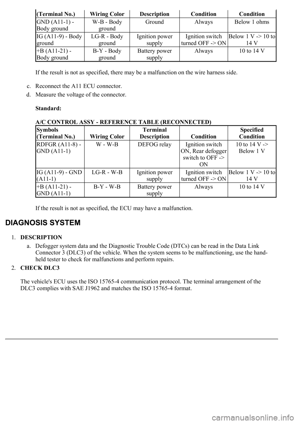
If the result is not as specified, there may be a malfunction on the wire harness side.
c. Reconnect the A11 ECU connector.
d. Measure the voltage of the connector.
Standard:
A/C CONTROL ASSY - REFERENCE TABLE (RECONNECTED)
If the result is not as specified, the ECU may have a malfunction.
1.DESCRIPTION
a. Defogger system data and the Diagnostic Trouble Code (DTCs) can be read in the Data Link
<002600520051005100480046005700520055000300160003000b0027002f00260016000c00030052004900030057004b0048000300590048004b004c0046004f004800110003003a004b0048005100030057004b004800030056005c005600570048005000
03005600480048005000560003005700520003004500480003[malfunctioning, use the hand-
held tester to check for malfunctions and perform repairs.
2.CHECK DLC3
The vehicle's ECU uses the ISO 15765-4 communication protocol. The terminal arrangement of the
DLC3 complies with SAE J1962 and matches the ISO 15765-4 format.
(Terminal No.)Wiring ColorDescriptionConditionCondition
GND (A11-1) -
Body groundW-B - Body
groundGroundAlwaysBelow 1 ohms
IG (A11-9) - Body
groundLG-R - Body
groundIgnition power
supplyIgnition switch
turned OFF -> ONBelow 1 V -> 10 to
14 V
+B (A11-21) -
Body groundB-Y - Body
groundBattery power
supplyAlways10 to 14 V
Symbols
(Terminal No.)
Wiring Color
Terminal
Description
Condition
Specified
Condition
RDFGR (A11-8) -
GND (A11-1)W - W-BDEFOG relayIgnition switch
ON, Rear defogger
switch to OFF ->
ON10 to 14 V ->
Below 1 V
IG (A11-9) - GND
(A11-1)LG-R - W-BIgnition power
supplyIgnition switch
turned OFF -> ONBelow 1 V -> 10 to
14 V
+B (A11-21) -
GND (A11-1)B-Y - W-BBattery power
supplyAlways10 to 14 V