Page 97 of 4500
Fig. 69: Identifying Skid Control ECU Connector Terminals
Courtesy of TOYOTA MOTOR SALES, U.S.A., INC.
NG: REPAIR OR REPLACE HARNESS OR CONNECTOR
OK: REPLACE ABS & TRACTION ACTUATOR ASSY (SEE REPLACEMENT
)
CIRCUIT DESCRIPTION
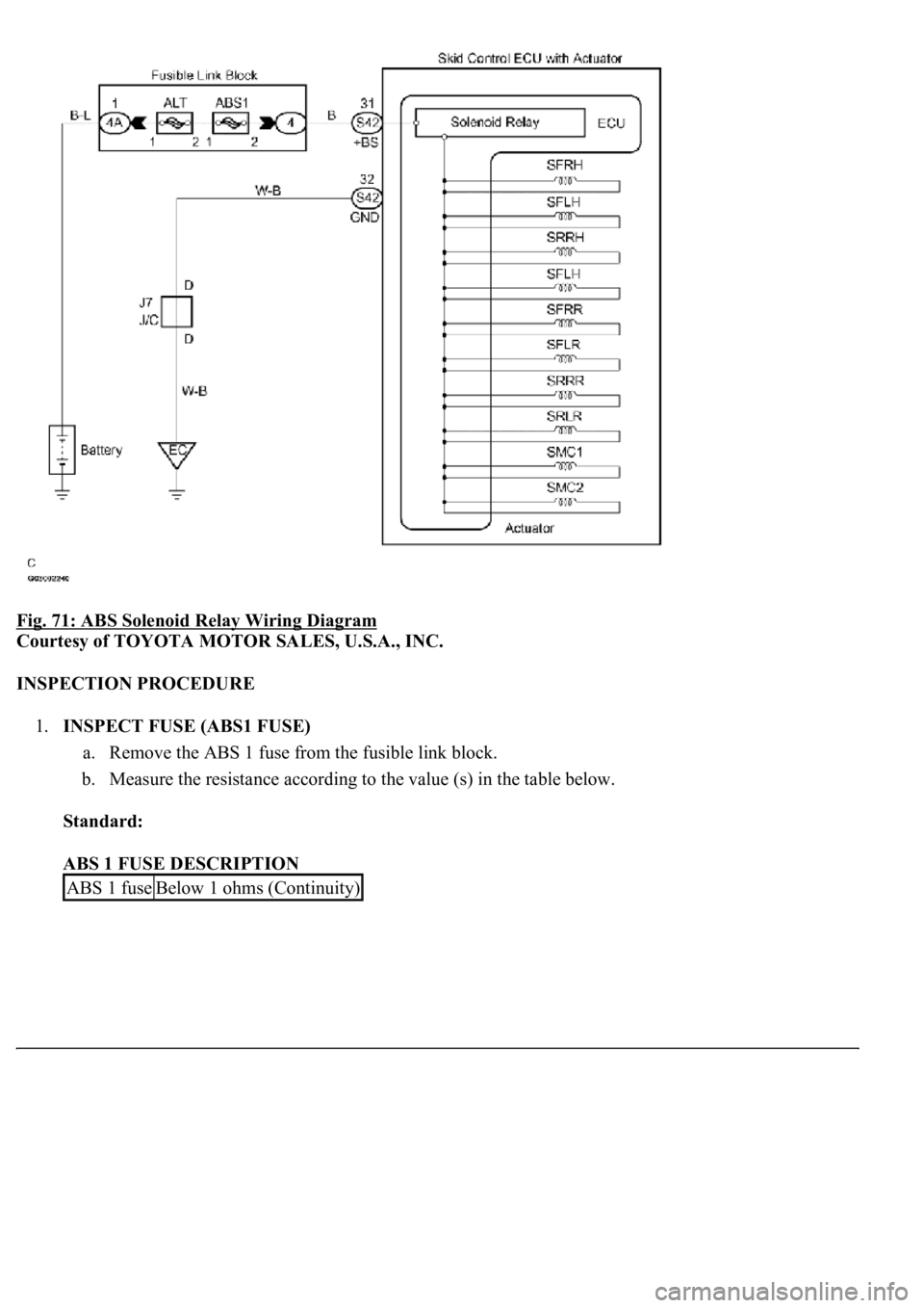
The ABS solenoid relay is built in the ABS & TRACTION Actuator assy. This relay supplies power to each
ABS solenoid. If the initial check is OK, after the ignition switch is turned to the ON position, the relay stays
on.
Fig. 70: DTC C0278/11 And DTC C0279/12 Detecting Condition And Trouble Area
Courtesy of TOYOTA MOTOR SALES, U.S.A., INC.
WIRING DIAGRAM
Page 98 of 4500
Fig. 71: ABS Solenoid Relay Wiring Diagram
Courtesy of TOYOTA MOTOR SALES, U.S.A., INC.
INSPECTION PROCEDURE
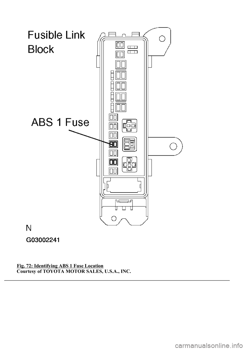
1.INSPECT FUSE (ABS1 FUSE)
a. Remove the ABS 1 fuse from the fusible link block.
b. Measure the resistance according to the value (s) in the table below.
Standard:
ABS 1 FUSE DESCRIPTION
ABS 1 fuseBelow 1 ohms (Continuity)
Page 99 of 4500
Fig. 72: Identifying ABS 1 Fuse Location
Courtesy of TOYOTA MOTOR SALES, U.S.A., INC.
Page 101 of 4500
Fig. 73: Identifying SKID Control ECU Connector Terminals
Courtesy of TOYOTA MOTOR SALES, U.S.A., INC.
3.RECONFIRM DTC
HINT:
This code is detected when a problem is determined in the brake actuator assy. The ABS solenoid circuit
is in the brake actuator assy. Therefore, solenoid circuit inspection relay unit inspection cannot be
performed. Be sure to check if the DTC code is output before replacing the brake actuator assy.
a. Clear the DTC (see DTC CHECK/CLEAR
).
b. Turn the ignition switch to the ON position.
c. Check that the same DTC is recorded.
OK: Go to next step
The same DTC is recorded.
NG: PROCEED TO NEXT CIRCUIT INSPECTION SHOWN IN PROBLEM SYMPTOMS
TABLE
Page 102 of 4500
HINT:
It is suspect that the DTCs output was caused by the poor connection on the connector terminal.
OK: REPLACE ABS & TRACTION ACTUATOR ASSY (SEE REPLACEMENT
)
CIRCUIT DESCRIPTION
If trouble occurs in the engine control system, the ECM transmits the abnormality to the skid control ECU. The
skid control ECU sets this DTC and the skid control ECU prohibits TRAC and VSC control.
DTC DETECTING CONDITION DESCRIPTION
INSPECTION PROCEDURE
1.CHECK HARNESS AND CONNECTOR (MOMENTARY INTERRUPTION)
a. Using the hand-held tester, check for any momentary interruption in the wire harness and connector
corresponding to a DTC (see CHECK FOR INTERMITTENT PROBLEMS
).
MEASUREMENT ITEM / RANGE (DISPLAY) DESCRIPTION
OK: Go to next step
There are no momentary interruptions.
HINT:
Perform the above inspection before removing the sensor and connector.
NG: REPAIR OR REPLACE HARNESS OR CONNECTOR (ECM - SKID CONTROL ECU)
OK: Go to next step
2.CHECK DTC FOR ENGINE
a. Check if the normal code is recorded for en
gine control system.
DTC No.DTC Detecting ConditionTrouble Area
C1201/51At the engine speed of 500 RPM, a trouble signal in the engine
control system continues for 5 secs, or more.Engine control
system
ItemMeasurement Item / Range (Display)Normal Condition
EFI COMEFI communication open detectionOPEN: Momentary interruption
Page 105 of 4500
HINT:
This DTC is output when the VSC system detects a malfunction in the ABS system.
When DTC C1223/43 is memorized, there is no malfunction in the skid control ECU.
CIRCUIT DESCRIPTION
DTC DETECTING CONDITION DESCRIPTION
INSPECTION PROCEDURE
1.CHECK DTC (FOR ABS SYSTEM)
a. Clear the DTC (see DTC CHECK/CLEAR
).
b. Turn the ignition switch to the ON position.
c. Check that the same DTC is recorded (see DTC CHECK/CLEAR
).
OK: Go to next step
The same DTC is recorded.
NG: PROCEED TO NEXT CIRCUIT INSPECTION SHOWN IN PROBLEM SYMPTOMS
TABLE
HINT:
It is suspect that the DTCs output was caused by the poor connection of the connector terminal.
OK REPAIR CIRCUIT INDICATED BY OUTPUT DTC
CIRCUIT DESCRIPTION
The steering angle sensor signal is sent to the skid control ECU through the CAN communication system. When
there is a malfunction in the communication, it will be detected by the diagnosis function.
DTC No.DTC Detecting ConditionTrouble Area
C1223/43Malfunction in ABS control systemABS control system
Page 109 of 4500
NG: Go to step 3
OK: REPLACE ABS & TRACTION ACTUATOR ASSY (SEE REPLACEMENT
)
3.CHECK TERMINAL VOLTAGE (STEERING ANGLE SENSOR CONNECTOR)
a. Remove the steering wheel and the column lower cover.
b. Disconnect the steering angle sensor connector.
c. Turn the ignition switch to the ON position.
d. Measure the voltage according to the value (s) in the table below.
Standard:
TESTER CONNECTION SPECIFIED CONDITION
e. Measure the voltage according to the value (s) in the table below.
Standard:
TESTER CONNECTION SPECIFIED CONDITION
Tester ConnectionSpecified Condition
S16-1 (IG1) - S16-2 (ESS)10 to 14V
Tester ConnectionSpecified Condition
S16-3 (BAT) -S16-2 (ESS)10 to 14V
Page 115 of 4500
TESTER CONNECTION SPECIFIED CONDITION
NG: REPAIR OR REPLACE HARNESS OR CONNECTOR
Fig. 82: Identifying Yaw Rate And Deceleration Sensor Connector Terminals (2 Of 2)
Courtesy of TOYOTA MOTOR SALES, U.S.A., INC.
OK: REPLACE ABS & TRACTION ACTUATOR ASSY (SEE REPLACEMENT
)
Tester ConnectionSpecified Condition
Y1-1 (GND) - Body groundBelow 1 ohms