Page 116 of 4500
CIRCUIT DESCRIPTION
The speed sensor detects wheel speed and sends the appropriate signals to the ECU. These signals are used to
control the ABS control system. The front and rear rotors have 48 serrations each.
When the rotors rotate, the magnetic field emitted by the permanent magnet in the speed sensor generates an
AC voltage. Since the frequency of this AC voltage changes in direct proportion to the speed of the rotor, the
frequenc
y is used by the ECU to detect the speed of each wheel.
Page 120 of 4500
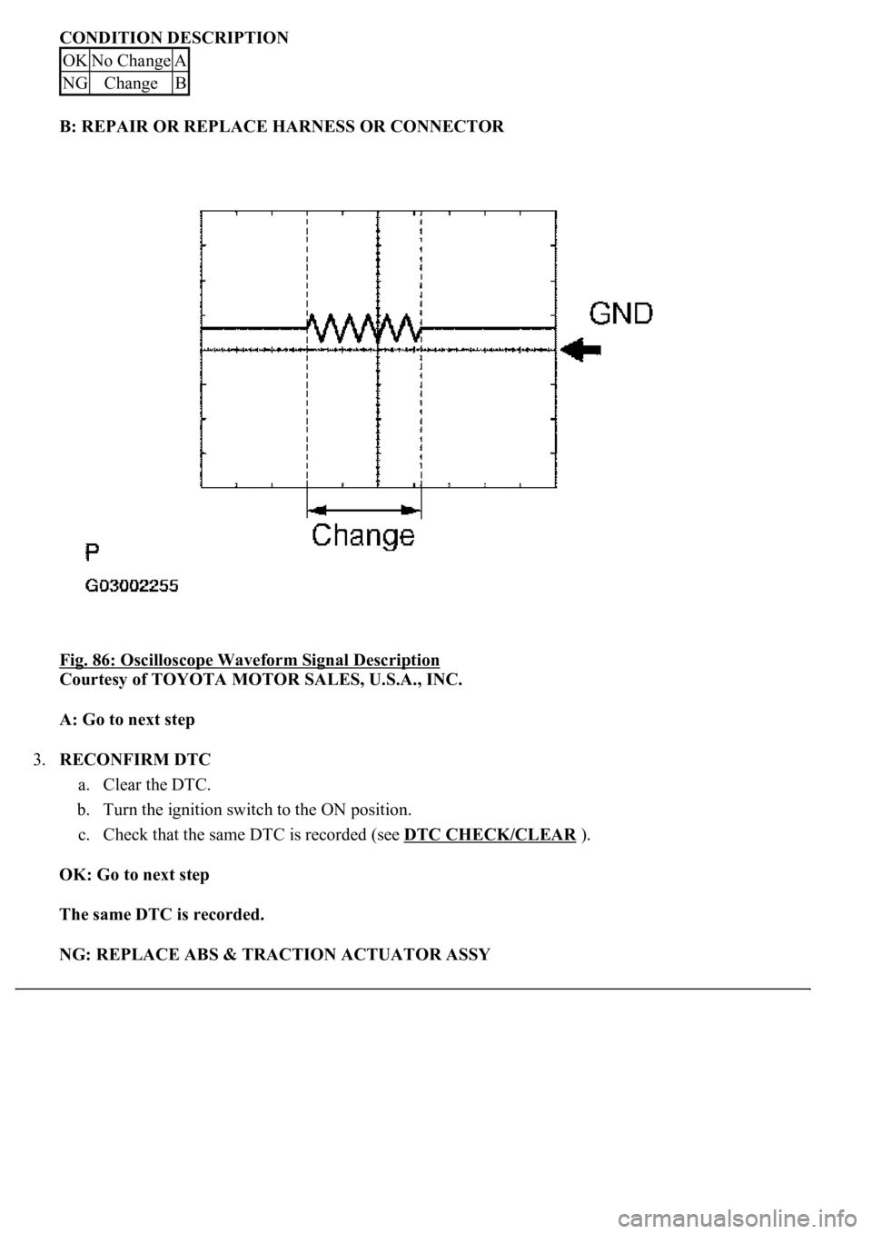
CONDITION DESCRIPTION
B: REPAIR OR REPLACE HARNESS OR CONNECTOR
Fig. 86: Oscilloscope Waveform Signal Description
Courtesy of TOYOTA MOTOR SALES, U.S.A., INC.
A: Go to next step
3.RECONFIRM DTC
a. Clear the DTC.
b. Turn the ignition switch to the ON position.
c. Check that the same DTC is recorded (see DTC CHECK/CLEAR
).
OK: Go to next step
The same DTC is recorded.
NG: REPLACE ABS & TRACTION ACTUATOR ASSY
OKNo ChangeA
NGChangeB
Page 123 of 4500
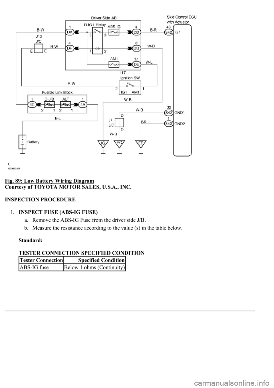
Fig. 89: Low Battery Wiring Diagram
Courtesy of TOYOTA MOTOR SALES, U.S.A., INC.
INSPECTION PROCEDURE
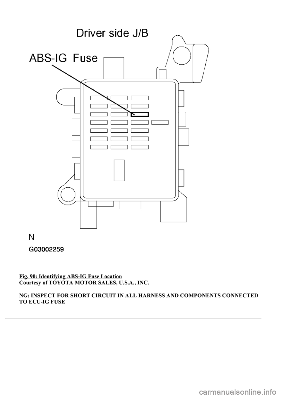
1.INSPECT FUSE (ABS-IG FUSE)
a. Remove the ABS-IG Fuse from the driver side J/B.
b. Measure the resistance according to the value (s) in the table below.
Standard:
TESTER CONNECTION SPECIFIED CONDITION
Tester ConnectionSpecified Condition
ABS-IG fuseBelow 1 ohms (Continuity)
Page 124 of 4500
Fig. 90: Identifying ABS-IG Fuse Location
Courtesy of TOYOTA MOTOR SALES, U.S.A., INC.
NG: INSPECT FOR SHORT CIRCUIT IN ALL HARNESS AND COMPONENTS CONNECTED
TO ECU-IG FUSE
Page 125 of 4500
OK: Go to next step
2.INSPECT BATTERY
a. Check the battery voltage.
Standard:
Voltage: 10 to 14 V
NG: INSPECT CHARGING SYSTEM (SEE ON
-VEHICLE INSPECTION )
OK: Go to next step
3.INSPECT SKID CONTROL ECU TERMINAL VOLTAGE (IG1 TERMINAL)
a. Connect the hand-held tester to the DLC3.
b. Start the engine.
c. Select the DATA LIST mode on the hand-held tester.
Fig. 91: DATA LIST Mode Description
Courtesy of TOYOTA MOTOR SALES, U.S.A., INC.
d. Read the voltage condition output from the ECU displayed on the hand-held tester.
Standard:
"Normal" is displayed.
NG: Go to step 4
OK: REPLACE ABS & TRACTION ACTUATOR ASSY (SEE REPLACEMENT
)
4.INSPECT SKID CONTROL ECU CONNECTOR (GND TERMINAL CONTINUITY)
a. Disconnect the skid control ECU connector.
b. Measure the resistance according to the value (s) in the table below.
Standard:
Page 128 of 4500

c. Select the DATA LIST mode on the hand-held tester.
MEASUREMENT ITEM / RANGE (DISPLAY) DESCRIPTION
d. Check that the brake fluid pressure value of the master cylinder pressure sensor observed in the
hand held tester changes when the brake pedal is depressed.
OK: Go to next step
When the pedal is depressed, displayed voltage on the hand-held tester increases.
NG: Go to step 2
OK: REPLACE ABS & TRACTION ACTUATOR ASSY (SEE REPLACEMENT
)
2.INSPECT SKID CONTROL ECU TERMINAL VOLTAGE (STP TERMINAL)
a. Disconnect the skid control ECU connector.
b. Measure the voltage according to the value (s) in the table below.
Standard:
TESTER CONNECTION SPECIFIED CONDITION
NG: CHECK AND REPLACE STOP LIGHT SWITCH CIRCUIT
OK: REPLACE ABS & TRACTION ACTUATOR ASSY (SEE REPLACEMENT
)
ItemMeasurement Item / Range (Display)Normal Condition
MAS CYL PRS
1Master cylinder pressure sensor 1 reading /
min.: 0 V, max.: 5 VWhen brake pedal is released:
0.3 to 0.9V
Tester ConnectionSwitch ConditionSpecified Condition
S42-27 (STP) - Body groundBrake pedal depressed8 to 14V
S42-27 (STP) - Body groundBrake pedal releasedBelow 1 V
Page 135 of 4500
OK: Go to next step
5.RECONFIRM DTC
a. Clear the DTC (see DTC CHECK/CLEAR
).
b. Turn the ignition switch to the ON position.
c. Check that the same DTC is recorded (see DTC CHECK/CLEAR
).
OK:
The same DTC is recorded.
NG: PROCEED TO NEXT CIRCUIT INSPECTION SHOWN IN PROBLEM SYMPTOMS
TABLE
OK: REPLACE ABS & TRACTION ACTUATOR ASSY (SEE REPLACEMENT
)
6.INSPECT STOP LAMP SWITCH ASSY
a. Disconnect the stop lamp switch assy connector.
b. Measure the resistance according to the value (s) in the table below.
Standard:
TESTER CONNECTION SPECIFIED CONDITION
Switch ConditionTester ConnectionSpecified Condition
Switch pin free1 - 2Below 1 ohms
Switch pin pushed in1 - 21 Mohms or higher
Page 140 of 4500
OK: Go to next step
9.RECONFIRM DTC
a. Clear the DTC (see DTC CHECK/CLEAR
).
b. Turn the ignition switch to the ON position.
c. Check that the same DTC is recorded (see DTC CHECK/CLEAR
).
OK:
The same DTC is recorded.
NG: PROCEED TO NEXT CIRCUIT INSPECTION SHOWN IN PROBLEM SYMPTOMS
TABLE
OK: REPLACE ABS & TRACTION ACTUATOR ASSY (SEE REPLACEMENT
)
CIRCUIT DESCRIPTION
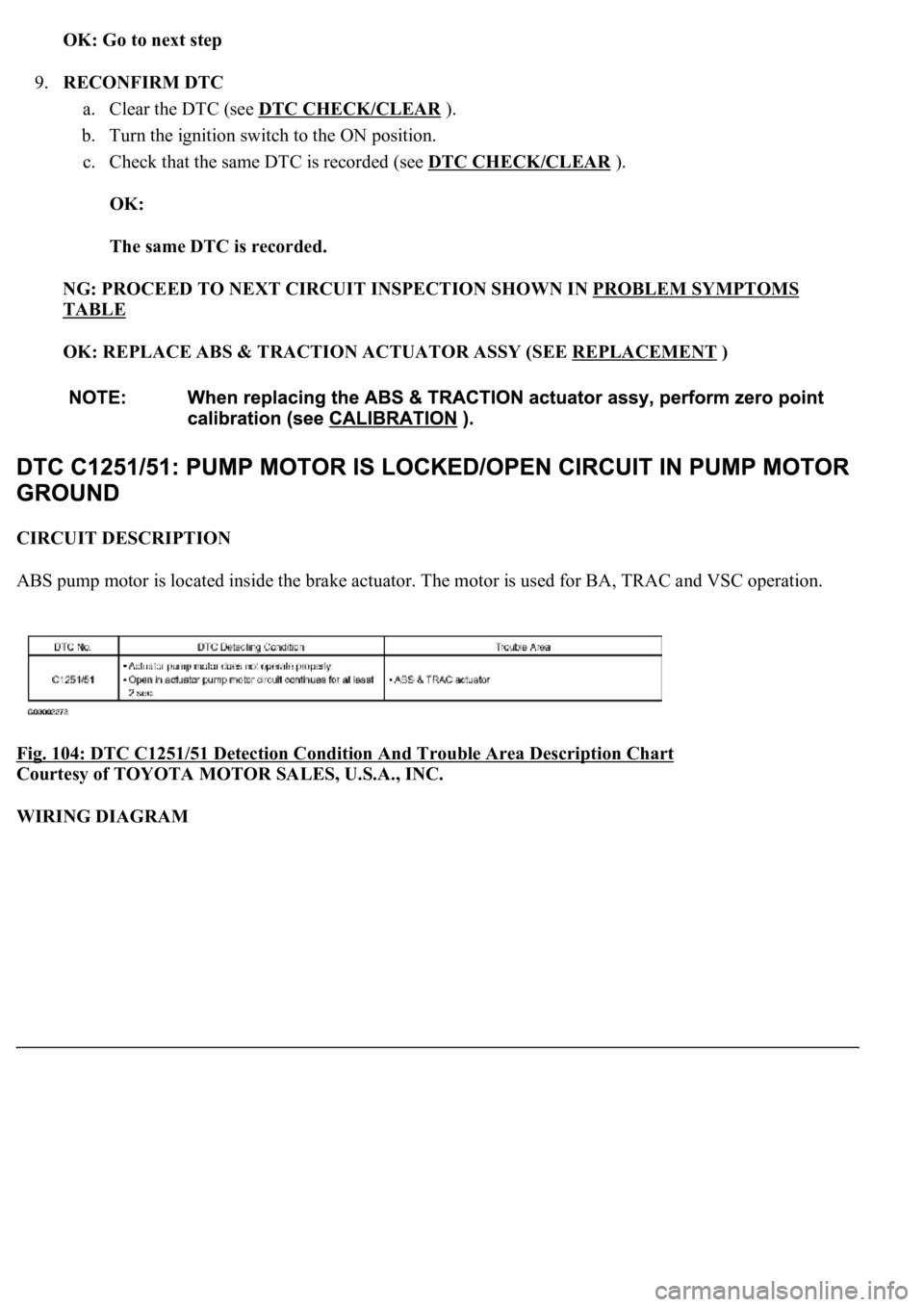
ABS pump motor is located inside the brake actuator. The motor is used for BA, TRAC and VSC operation.
Fig. 104: DTC C1251/51 Detection Condition And Trouble Area Description Chart
Courtesy of TOYOTA MOTOR SALES, U.S.A., INC.
WIRING DIAGRAM