Page 1549 of 4500
Fig. 38: Identifying Clearance Warning ECU Assy Terminals
Courtesy of TOYOTA MOTOR SALES, U.S.A., INC.
NG: REPAIR OR REPLACE HARNESS OR CONNECTOR
OK: REPLACE CLEARANCE WARNING ECU ASSY (SEE REPLACEMENT
)
CIRCUIT DESCRIPTION
Ultrasonic sensor consists of a sensor portion that transmits and receives ultrasonic waves and a pre-amplifier
that amplifies them. The ultrasonic sensor outputs the ultrasonic transmission and reception signals to the
clearance warning ECU assy.
Fig. 39: DTC B2236 Detection Condition And Trouble Area Description Chart
Courtesy of TOYOTA MOTOR SALES, U.S.A., INC.
WIRING DIAGRAM
Page 1553 of 4500
Fig. 42: Identifying Clearance Warning ECU Assy Terminals
Courtesy of TOYOTA MOTOR SALES, U.S.A., INC.
NG: REPAIR OR REPLACE HARNESS OR CONNECTOR
OK: REPLACE CLEARANCE WARNING ECU ASSY (SEE REPLACEMENT
)
CIRCUIT DESCRIPTION
Ultrasonic sensor consists of a sensor portion that transmits and receives ultrasonic waves and a pre-amplifier
that amplifies them. The ultrasonic sensor outputs the ultrasonic transmission and reception signals to the
clearance warning ECU assy.
Fig. 43: DTC B2237 Detection Condition And Trouble Area Description Chart
Courtesy of TOYOTA MOTOR SALES, U.S.A., INC.
WIRING DIAGRAM
Page 1557 of 4500
Fig. 46: Identifying Clearance Warning ECU Assy Terminals
Courtesy of TOYOTA MOTOR SALES, U.S.A., INC.
NG: REPAIR OR REPLACE HARNESS OR CONNECTOR
OK: REPLACE CLEARANCE WARNING ECU ASSY (SEE REPLACEMENT
)
CIRCUIT DESCRIPTION
Ultrasonic sensor consists of a sensor portion that transmits and receives ultrasonic waves and a pre-amplifier
that amplifies them. The ultrasonic sensor outputs the ultrasonic transmission and reception signals to the
clearance warning ECU assy.
Fig. 47: DTC B2238 Detection Condition And Trouble Area Description Chart
Courtesy of TOYOTA MOTOR SALES, U.S.A., INC.
WIRING DIAGRAM
Page 1561 of 4500
Fig. 50: Identifying Clearance Warning ECU Assy Terminals
Courtesy of TOYOTA MOTOR SALES, U.S.A., INC.
NG: REPAIR OR REPLACE HARNESS OR CONNECTOR
OK: REPLACE CLEARANCE WARNING ECU ASSY (SEE REPLACEMENT
)
CIRCUIT DESCRIPTION
Ultrasonic sensor consists of a sensor portion that transmits and receives ultrasonic waves and a pre-amplifier
that amplifies them. The ultrasonic sensor outputs the ultrasonic transmission and reception signals to the
clearance warning ECU assy.
Fig. 51: DTC B2239 Detection Condition And Trouble Area Description Chart
Courtesy of TOYOTA MOTOR SALES, U.S.A., INC.
WIRING DIAGRAM
Page 1565 of 4500
Fig. 54: Identifying Clearance Warning ECU Assy Terminals
Courtesy of TOYOTA MOTOR SALES, U.S.A., INC.
NG: REPAIR OR REPLACE HARNESS OR CONNECTOR
OK: REPLACE CLEARANCE WARNING ECU ASSY (SEE REPLACEMENT
)
CIRCUIT DESCRIPTION
Ultrasonic sensor consists of a sensor portion that transmits and receives ultrasonic waves and a pre-amplifier
that amplifies them. The ultrasonic sensor outputs the ultrasonic transmission and reception signals to the
clearance warning ECU assy.
Fig. 55: DTC B2241 Detection Condition And Trouble Area Description Chart
Courtesy of TOYOTA MOTOR SALES, U.S.A., INC.
WIRING DIAGRAM
Page 3166 of 4500

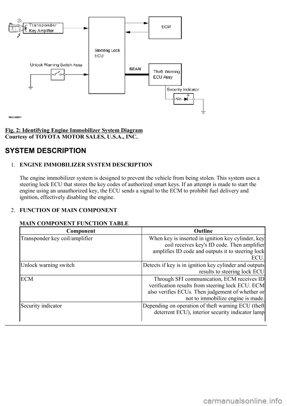
Fig. 2: Identifying Engine Immobilizer System Diagram
Courtesy of TOYOTA MOTOR SALES, U.S.A., INC.
1.ENGINE IMMOBILIZER SYSTEM DESCRIPTION
The engine immobilizer system is designed to prevent the vehicle from being stolen. This system uses a
steering lock ECU that stores the key codes of authorized smart keys. If an attempt is made to start the
engine using an unauthorized key, the ECU sends a signal to the ECM to prohibit fuel delivery and
ignition, effectively disabling the engine.
2.FUNCTION OF MAIN COMPONENT
MAIN COMPONENT FUNCTION TABLE
ComponentOutline
Transponder key coil/amplifierWhen key is inserted in ignition key cylinder, key
coil receives key's ID code. Then amplifier
amplifies ID code and outputs it to steering lock
ECU.
Unlock warning switchDetects if key is in ignition key cylinder and outputs
results to steering lock ECU
ECMThrough SFI communication, ECM receives ID
verification results from steering lock ECU. ECM
also verifies ECUs. Then judgement of whether or
not to immobilize engine is made.
Security indicatorDepending on operation of theft warning ECU (theft
deterrent ECU), interior security indicator lamp
Page 3212 of 4500
Fig. 36: Checking Wire Harness (Steering Lock ECU -Transponder Key Amplifier)
Courtesy of TOYOTA MOTOR SALES, U.S.A., INC.
NG: REPAIR OR REPLACE HARNESS AND CONNECTOR
OK: Go to next step
4.REPLACE TRANSPONDER KEY AMPLIFIER
a. After replacing the transponder key amplifier with a normally functioning amplifier, check that the
engine starts.
OK: Engine starts.
NG: REPLACE STEERING LOCK ECU
OK: END
CIRCUIT DESCRIPTION
This DTC is output when a communication error occurs between the transponder key amplifier and steering
lock ECU. Some possible reasons for the communication error are: 1) 2 or more smart keys are positioned too
close together, or 2) noise is occurring in the communication line. Follow the inspection procedure below.
Fig. 37: Communication Malfunction No. 1 Circuit Description
Courtesy of TOYOTA MOTOR SALES, U.S.A., INC.
WIRING DIAGRAM
Page 3218 of 4500

Fig. 41: Checking Wire Harness (Steering Lock ECU -Transponder Key Amplifier)
Courtesy of TOYOTA MOTOR SALES, U.S.A., INC.
NG: REPAIR OR REPLACE HARNESS AND CONNECTOR
OK: Go to next step
5.CHECK OPERATION OF TRANSPONDER KEY AMPLIFIER
a. After replacing the transponder key amplifier with a normally functioning amplifier, check that the
engine starts.
OK: Engine starts.
NG: REPLACE STEERING LOCK ECU
OK: END
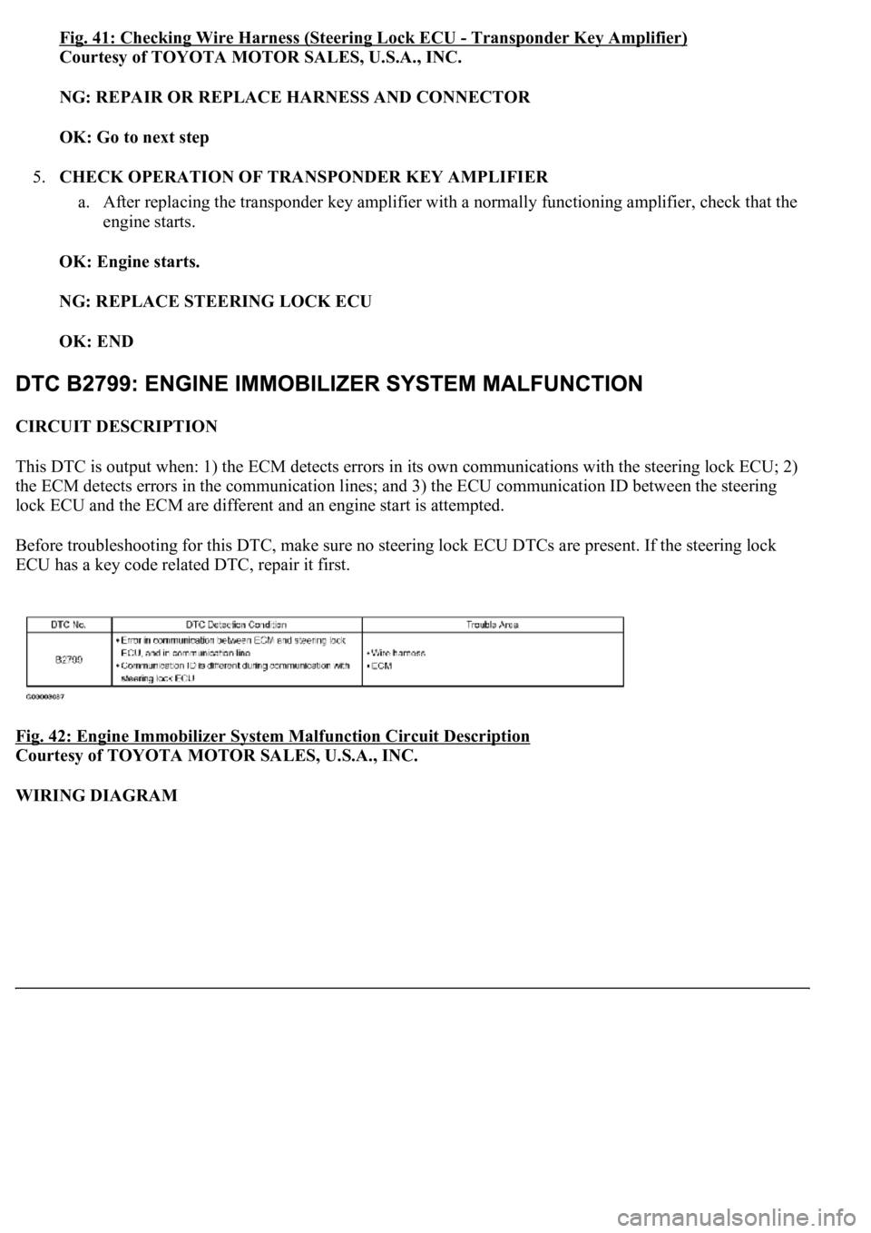
CIRCUIT DESCRIPTION
This DTC is output when: 1) the ECM detects errors in its own communications with the steering lock ECU; 2)
the ECM detects errors in the communication lines; and 3) the ECU communication ID between the steering
lock ECU and the ECM are different and an engine start is attempted.
Before troubleshooting for this DTC, make sure no steering lock ECU DTCs are present. If the steering lock
ECU has a key code related DTC, repair it first.
Fig. 42: Engine Immobilizer System Malfunction Circuit Description
Courtesy of TOYOTA MOTOR SALES, U.S.A., INC.
WIRING DIAGRAM