Page 4182 of 4500

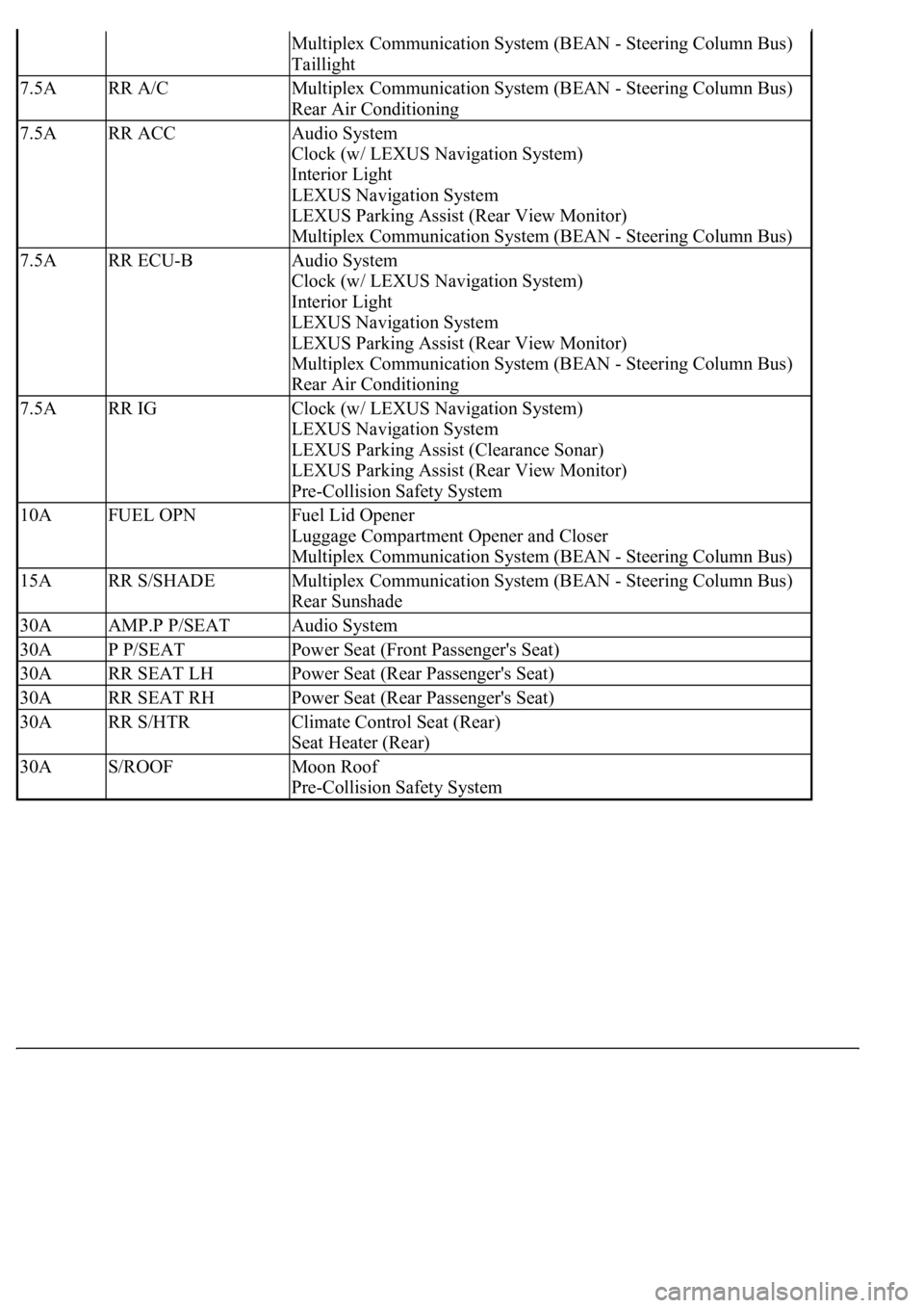
Multiplex Communication System (BEAN - Steering Column Bus)
Taillight
7.5ARR A/CMultiplex Communication System (BEAN - Steering Column Bus)
Rear Air Conditioning
7.5ARR ACCAudio System
Clock (w/ LEXUS Navigation System)
Interior Light
LEXUS Navigation System
LEXUS Parking Assist (Rear View Monitor)
Multiplex Communication System (BEAN - Steering Column Bus)
7.5ARR ECU-BAudio System
Clock (w/ LEXUS Navigation System)
Interior Light
LEXUS Navigation System
LEXUS Parking Assist (Rear View Monitor)
Multiplex Communication System (BEAN - Steering Column Bus)
Rear Air Conditioning
7.5ARR IGClock (w/ LEXUS Navigation System)
LEXUS Navigation System
LEXUS Parking Assist (Clearance Sonar)
LEXUS Parking Assist (Rear View Monitor)
Pre-Collision Safety System
10AFUEL OPNFuel Lid Opener
Luggage Compartment Opener and Closer
Multiplex Communication System (BEAN - Steering Column Bus)
15ARR S/SHADEMultiplex Communication System (BEAN - Steering Column Bus)
Rear Sunshade
30AAMP.P P/SEATAudio System
30AP P/SEATPower Seat (Front Passenger's Seat)
30ARR SEAT LHPower Seat (Rear Passenger's Seat)
30ARR SEAT RHPower Seat (Rear Passenger's Seat)
30ARR S/HTRClimate Control Seat (Rear)
Seat Heater (Rear)
30AS/ROOFMoon Roof
Pre-Collision Safety System
Page 4409 of 4500
Fig. 9: Disconnecting Fuel Pipe Sub-Assy No. 2
Courtesy of TOYOTA MOTOR SALES, U.S.A., INC.
13.REMOVE INTAKE MANIFOLD
a. Remove the bolt and the water by-pass pipe No. 1 and No. 2.
b. Disconnect the vacuum hose for the brake booster.
c. Disconnect the air hose for the power steering.
d. Disconnect the ventilation hose.
e. Disconnect the injector connector.
f. Remove the 6 bolts, 4 nuts and intake manifold.
14.REMOVE INTAKE MANIFOLD TO HEAD GASKET NO. 1
15.INSTALL INTAKE MANIFOLD TO HEAD GASKET NO. 1
a. Install 2 new gaskets to the cylinder head.
HINT:
The white-painted area on each gasket should face up as shown in the illustration.
Page 4410 of 4500
Fig. 10: Installing Intake Manifold To Head Gasket No. 1
Courtesy of TOYOTA MOTOR SALES, U.S.A., INC.
16.INSTALL INTAKE MANIFOLD
a. Install the intake manifold with the 6 bolts and 4 nuts.
Torque: 18 N.m (184 kgf.cm, 13 ft.lbf)
b. Connect the injector connector.
c. Connect the ventilation hose.
d. Connect the air hose for the power steering.
e. Connect the vacuum hose for the brake booster.
f. Install the water by-pass pipe No. 1 and No. 2 with the bolt.
17.CONNECT FUEL PIPE SUB-ASSY NO. 2
a. Using SST, install the fuel main hose.
SST 09023-38401
Page 4423 of 4500
Fig. 8: Identifying Terminals Of Steering Lock ECU
Courtesy of TOYOTA MOTOR SALES, U.S.A., INC.
a. Disconnect the S46 ECU connector.
b. Measure the voltage and resistance of the wire harness side connector.
Standard:
SPECIFIED CONDITION
Symbols
(Terminal No.)Wiring
ColorTerminal
DescriptionConditionSpecified Condition
CPUB (S46-1) -
Body groundV-Y - Body
ground+B (CPUB)
Power supplyAlways10 to 14V
+B (S46-10)-
Body groundR-L - Body
ground+B Power supplyAlways10 to 14V
LG-B -1: No key in starter