2003 LEXUS LS430 power steering
[x] Cancel search: power steeringPage 2629 of 4500
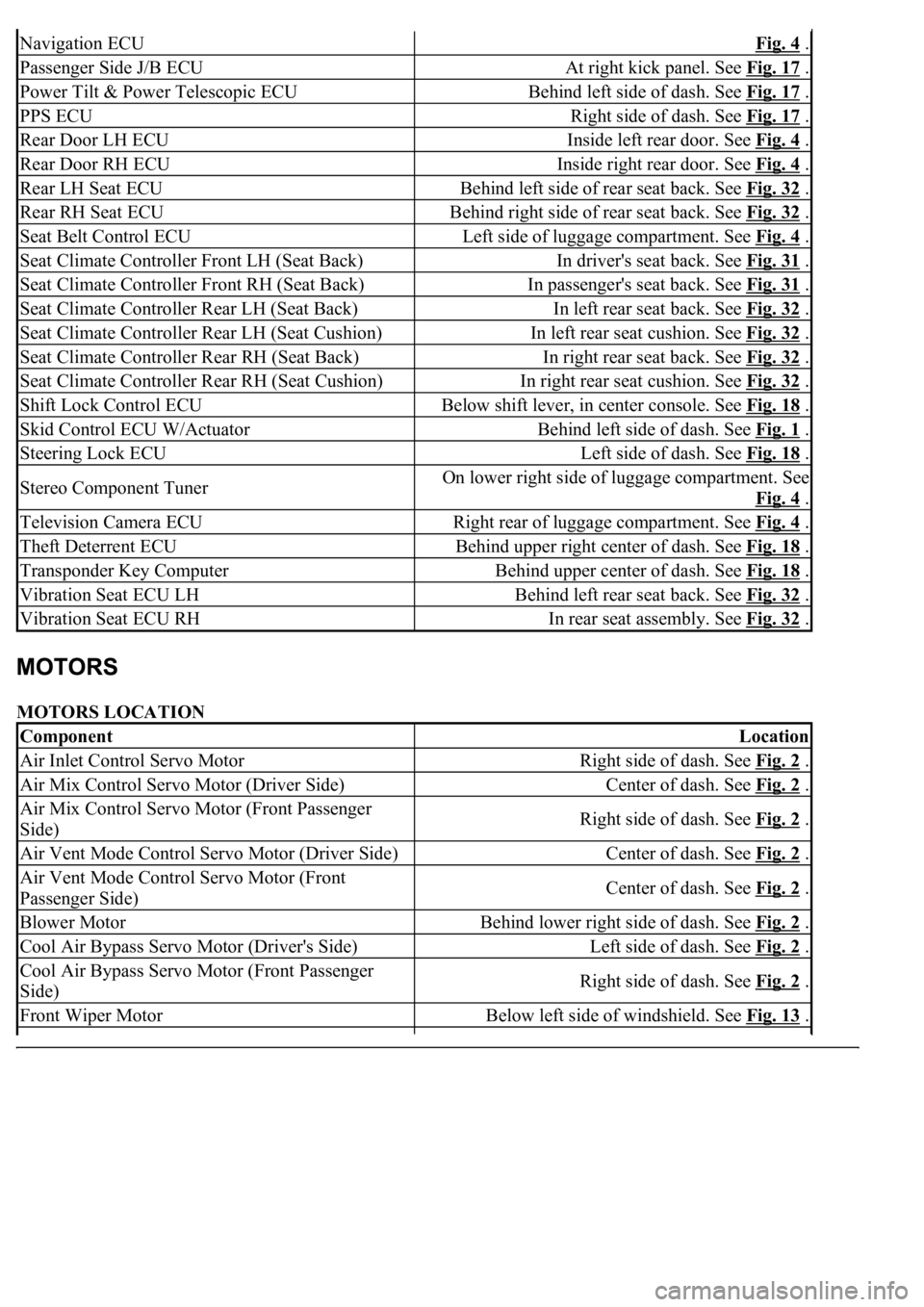
MOTORS LOCATION
Navigation ECUFig. 4 .
Passenger Side J/B ECUAt right kick panel. See Fig. 17 .
Power Tilt & Power Telescopic ECUBehind left side of dash. See Fig. 17 .
PPS ECURight side of dash. See Fig. 17 .
Rear Door LH ECUInside left rear door. See Fig. 4 .
Rear Door RH ECUInside right rear door. See Fig. 4 .
Rear LH Seat ECUBehind left side of rear seat back. See Fig. 32 .
Rear RH Seat ECUBehind right side of rear seat back. See Fig. 32 .
Seat Belt Control ECULeft side of luggage compartment. See Fig. 4 .
Seat Climate Controller Front LH (Seat Back)In driver's seat back. See Fig. 31 .
Seat Climate Controller Front RH (Seat Back)In passenger's seat back. See Fig. 31 .
Seat Climate Controller Rear LH (Seat Back)In left rear seat back. See Fig. 32 .
Seat Climate Controller Rear LH (Seat Cushion)In left rear seat cushion. See Fig. 32 .
Seat Climate Controller Rear RH (Seat Back)In right rear seat back. See Fig. 32 .
Seat Climate Controller Rear RH (Seat Cushion)In right rear seat cushion. See Fig. 32 .
Shift Lock Control ECUBelow shift lever, in center console. See Fig. 18 .
Skid Control ECU W/ActuatorBehind left side of dash. See Fig. 1 .
Steering Lock ECULeft side of dash. See Fig. 18 .
Stereo Component TunerOn lower right side of luggage compartment. See
Fig. 4
.
Television Camera ECURight rear of luggage compartment. See Fig. 4 .
Theft Deterrent ECUBehind upper right center of dash. See Fig. 18 .
Transponder Key ComputerBehind upper center of dash. See Fig. 18 .
Vibration Seat ECU LHBehind left rear seat back. See Fig. 32 .
Vibration Seat ECU RHIn rear seat assembly. See Fig. 32 .
ComponentLocation
Air Inlet Control Servo MotorRight side of dash. See Fig. 2 .
Air Mix Control Servo Motor (Driver Side)Center of dash. See Fig. 2 .
Air Mix Control Servo Motor (Front Passenger
Side)Right side of dash. See Fig. 2 .
Air Vent Mode Control Servo Motor (Driver Side)Center of dash. See Fig. 2 .
Air Vent Mode Control Servo Motor (Front
Passenger Side)Center of dash. See Fig. 2 .
Blower MotorBehind lower right side of dash. See Fig. 2 .
Cool Air Bypass Servo Motor (Driver's Side)Left side of dash. See Fig. 2 .
Cool Air Bypass Servo Motor (Front Passenger
Side)Right side of dash. See Fig. 2 .
Front Wiper MotorBelow left side of windshield. See Fig. 13 .
Page 2633 of 4500
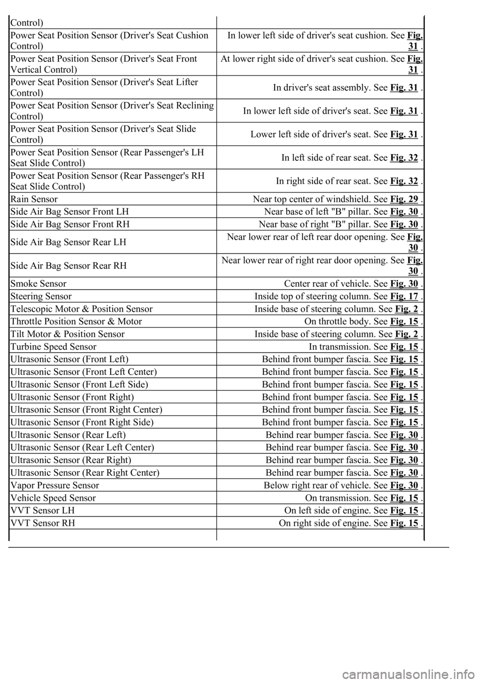
Control)
Power Seat Position Sensor (Driver's Seat Cushion
Control)In lower left side of driver's seat cushion. See Fig.
31 .
Power Seat Position Sensor (Driver's Seat Front
Vertical Control)At lower right side of driver's seat cushion. See Fig.
31 .
Power Seat Position Sensor (Driver's Seat Lifter
Control)In driver's seat assembly. See Fig. 31 .
Power Seat Position Sensor (Driver's Seat Reclining
Control)In lower left side of driver's seat. See Fig. 31 .
Power Seat Position Sensor (Driver's Seat Slide
Control)Lower left side of driver's seat. See Fig. 31 .
Power Seat Position Sensor (Rear Passenger's LH
Seat Slide Control)In left side of rear seat. See Fig. 32 .
Power Seat Position Sensor (Rear Passenger's RH
Seat Slide Control)In right side of rear seat. See Fig. 32 .
Rain SensorNear top center of windshield. See Fig. 29 .
Side Air Bag Sensor Front LHNear base of left "B" pillar. See Fig. 30 .
Side Air Bag Sensor Front RHNear base of right "B" pillar. See Fig. 30 .
Side Air Bag Sensor Rear LHNear lower rear of left rear door opening. See Fig.
30 .
Side Air Bag Sensor Rear RHNear lower rear of right rear door opening. See Fig.
30 .
Smoke SensorCenter rear of vehicle. See Fig. 30 .
Steering SensorInside top of steering column. See Fig. 17 .
Telescopic Motor & Position SensorInside base of steering column. See Fig. 2 .
Throttle Position Sensor & MotorOn throttle body. See Fig. 15 .
Tilt Motor & Position SensorInside base of steering column. See Fig. 2 .
Turbine Speed SensorIn transmission. See Fig. 15 .
Ultrasonic Sensor (Front Left)Behind front bumper fascia. See Fig. 15 .
Ultrasonic Sensor (Front Left Center)Behind front bumper fascia. See Fig. 15 .
Ultrasonic Sensor (Front Left Side)Behind front bumper fascia. See Fig. 15 .
Ultrasonic Sensor (Front Right)Behind front bumper fascia. See Fig. 15 .
Ultrasonic Sensor (Front Right Center)Behind front bumper fascia. See Fig. 15 .
Ultrasonic Sensor (Front Right Side)Behind front bumper fascia. See Fig. 15 .
Ultrasonic Sensor (Rear Left)Behind rear bumper fascia. See Fig. 30 .
Ultrasonic Sensor (Rear Left Center)Behind rear bumper fascia. See Fig. 30 .
Ultrasonic Sensor (Rear Right)Behind rear bumper fascia. See Fig. 30 .
Ultrasonic Sensor (Rear Right Center)Behind rear bumper fascia. See Fig. 30 .
Vapor Pressure SensorBelow right rear of vehicle. See Fig. 30 .
Vehicle Speed SensorOn transmission. See Fig. 15 .
VVT Sensor LHOn left side of engine. See Fig. 15 .
VVT Sensor RHOn right side of engine. See Fig. 15 .
Page 2635 of 4500
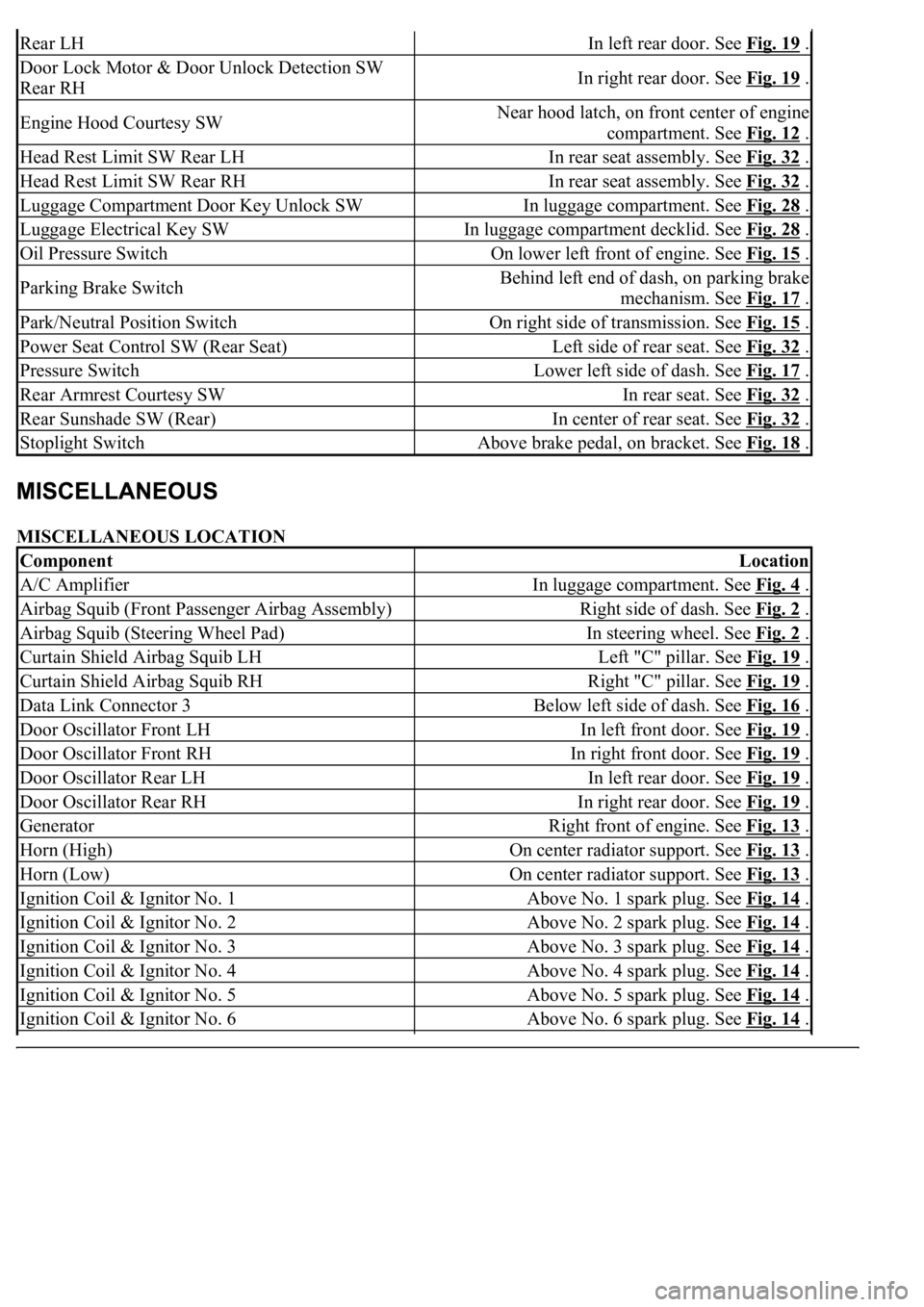
MISCELLANEOUS LOCATION
Rear LHIn left rear door. See Fig. 19 .
Door Lock Motor & Door Unlock Detection SW
Rear RHIn right rear door. See Fig. 19 .
Engine Hood Courtesy SWNear hood latch, on front center of engine
compartment. See Fig. 12
.
Head Rest Limit SW Rear LHIn rear seat assembly. See Fig. 32 .
Head Rest Limit SW Rear RHIn rear seat assembly. See Fig. 32 .
Luggage Compartment Door Key Unlock SWIn luggage compartment. See Fig. 28 .
Luggage Electrical Key SWIn luggage compartment decklid. See Fig. 28 .
Oil Pressure SwitchOn lower left front of engine. See Fig. 15 .
Parking Brake SwitchBehind left end of dash, on parking brake
mechanism. See Fig. 17
.
Park/Neutral Position SwitchOn right side of transmission. See Fig. 15 .
Power Seat Control SW (Rear Seat)Left side of rear seat. See Fig. 32 .
Pressure SwitchLower left side of dash. See Fig. 17 .
Rear Armrest Courtesy SWIn rear seat. See Fig. 32 .
Rear Sunshade SW (Rear)In center of rear seat. See Fig. 32 .
Stoplight SwitchAbove brake pedal, on bracket. See Fig. 18 .
ComponentLocation
A/C AmplifierIn luggage compartment. See Fig. 4 .
Airbag Squib (Front Passenger Airbag Assembly)Right side of dash. See Fig. 2 .
Airbag Squib (Steering Wheel Pad)In steering wheel. See Fig. 2 .
Curtain Shield Airbag Squib LHLeft "C" pillar. See Fig. 19 .
Curtain Shield Airbag Squib RHRight "C" pillar. See Fig. 19 .
Data Link Connector 3Below left side of dash. See Fig. 16 .
Door Oscillator Front LHIn left front door. See Fig. 19 .
Door Oscillator Front RHIn right front door. See Fig. 19 .
Door Oscillator Rear LHIn left rear door. See Fig. 19 .
Door Oscillator Rear RHIn right rear door. See Fig. 19 .
GeneratorRight front of engine. See Fig. 13 .
Horn (High)On center radiator support. See Fig. 13 .
Horn (Low)On center radiator support. See Fig. 13 .
Ignition Coil & Ignitor No. 1Above No. 1 spark plug. See Fig. 14 .
Ignition Coil & Ignitor No. 2Above No. 2 spark plug. See Fig. 14 .
Ignition Coil & Ignitor No. 3Above No. 3 spark plug. See Fig. 14 .
Ignition Coil & Ignitor No. 4Above No. 4 spark plug. See Fig. 14 .
Ignition Coil & Ignitor No. 5Above No. 5 spark plug. See Fig. 14 .
Ignition Coil & Ignitor No. 6Above No. 6 spark plug. See Fig. 14 .
Page 2670 of 4500
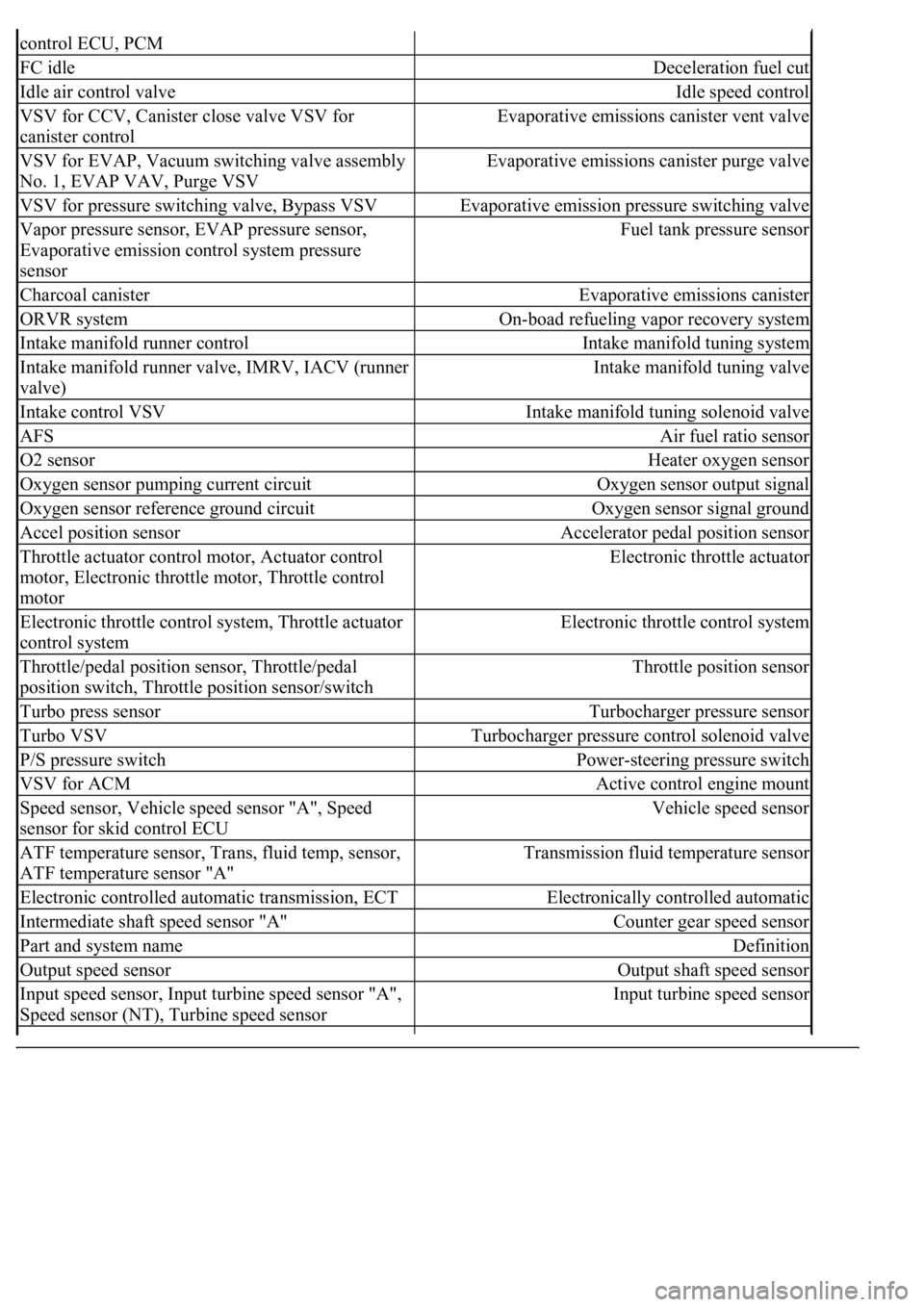
control ECU, PCM
FC idleDeceleration fuel cut
Idle air control valveIdle speed control
VSV for CCV, Canister close valve VSV for
canister controlEvaporative emissions canister vent valve
VSV for EVAP, Vacuum switching valve assembly
No. 1, EVAP VAV, Purge VSVEvaporative emissions canister purge valve
VSV for pressure switching valve, Bypass VSVEvaporative emission pressure switching valve
Vapor pressure sensor, EVAP pressure sensor,
Evaporative emission control system pressure
sensorFuel tank pressure sensor
Charcoal canisterEvaporative emissions canister
ORVR systemOn-boad refueling vapor recovery system
Intake manifold runner controlIntake manifold tuning system
Intake manifold runner valve, IMRV, IACV (runner
valve)Intake manifold tuning valve
Intake control VSVIntake manifold tuning solenoid valve
AFSAir fuel ratio sensor
O2 sensorHeater oxygen sensor
Oxygen sensor pumping current circuitOxygen sensor output signal
Oxygen sensor reference ground circuitOxygen sensor signal ground
Accel position sensorAccelerator pedal position sensor
Throttle actuator control motor, Actuator control
motor, Electronic throttle motor, Throttle control
motorElectronic throttle actuator
Electronic throttle control system, Throttle actuator
control systemElectronic throttle control system
Throttle/pedal position sensor, Throttle/pedal
position switch, Throttle position sensor/switchThrottle position sensor
Turbo press sensorTurbocharger pressure sensor
Turbo VSVTurbocharger pressure control solenoid valve
P/S pressure switchPower-steering pressure switch
VSV for ACMActive control engine mount
Speed sensor, Vehicle speed sensor "A", Speed
sensor for skid control ECUVehicle speed sensor
ATF temperature sensor, Trans, fluid temp, sensor,
ATF temperature sensor "A"Transmission fluid temperature sensor
Electronic controlled automatic transmission, ECTElectronically controlled automatic
Intermediate shaft speed sensor "A"Counter gear speed sensor
Part and system nameDefinition
Output speed sensorOutput shaft speed sensor
<002c00510053005800570003005600530048004800470003005600480051005600520055000f0003002c005100530058005700030057005800550045004c005100480003005600530048004800470003005600480051005600520055000300050024000500
0f0003[
Speed sensor (NT), Turbine speed sensorInput turbine speed sensor
Page 3186 of 4500
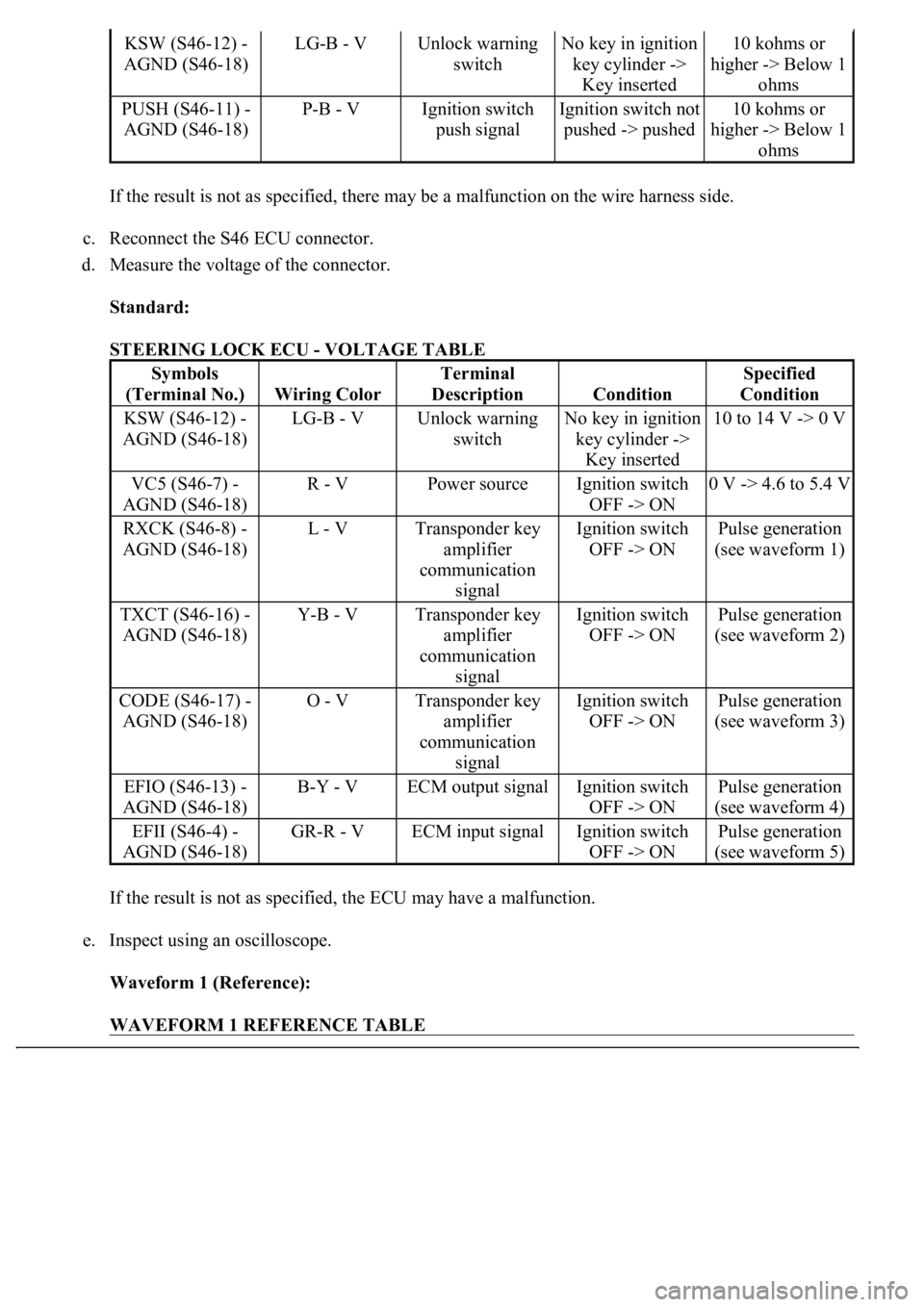
If the result is not as specified, there may be a malfunction on the wire harness side.
c. Reconnect the S46 ECU connector.
d. Measure the voltage of the connector.
Standard:
STEERING LOCK ECU - VOLTAGE TABLE
If the result is not as specified, the ECU may have a malfunction.
e. Inspect using an oscilloscope.
Waveform 1 (Reference):
WAVEFORM 1 REFERENCE TABLE
KSW (S46-12) -
AGND (S46-18)LG-B - VUnlock warning
switchNo key in ignition
key cylinder ->
Key inserted10 kohms or
higher -> Below 1
ohms
PUSH (S46-11) -
AGND (S46-18)P-B - VIgnition switch
push signalIgnition switch not
pushed -> pushed10 kohms or
higher -> Below 1
ohms
Symbols
(Terminal No.)
Wiring Color
Terminal
Description
Condition
Specified
Condition
KSW (S46-12) -
AGND (S46-18)LG-B - VUnlock warning
switchNo key in ignition
key cylinder ->
Key inserted10 to 14 V -> 0 V
VC5 (S46-7) -
AGND (S46-18)R - VPower sourceIgnition switch
OFF -> ON0 V -> 4.6 to 5.4 V
RXCK (S46-8) -
AGND (S46-18)L - VTransponder key
amplifier
communication
signalIgnition switch
OFF -> ONPulse generation
(see waveform 1)
TXCT (S46-16) -
AGND (S46-18)Y-B - VTransponder key
amplifier
communication
signalIgnition switch
OFF -> ONPulse generation
(see waveform 2)
CODE (S46-17) -
AGND (S46-18)O - VTransponder key
amplifier
communication
signalIgnition switch
OFF -> ONPulse generation
(see waveform 3)
EFIO (S46-13) -
AGND (S46-18)B-Y - VECM output signalIgnition switch
OFF -> ONPulse generation
(see waveform 4)
EFII (S46-4) -
AGND (S46-18)GR-R - VECM input signalIgnition switch
OFF -> ONPulse generation
(see waveform 5)
Page 3221 of 4500
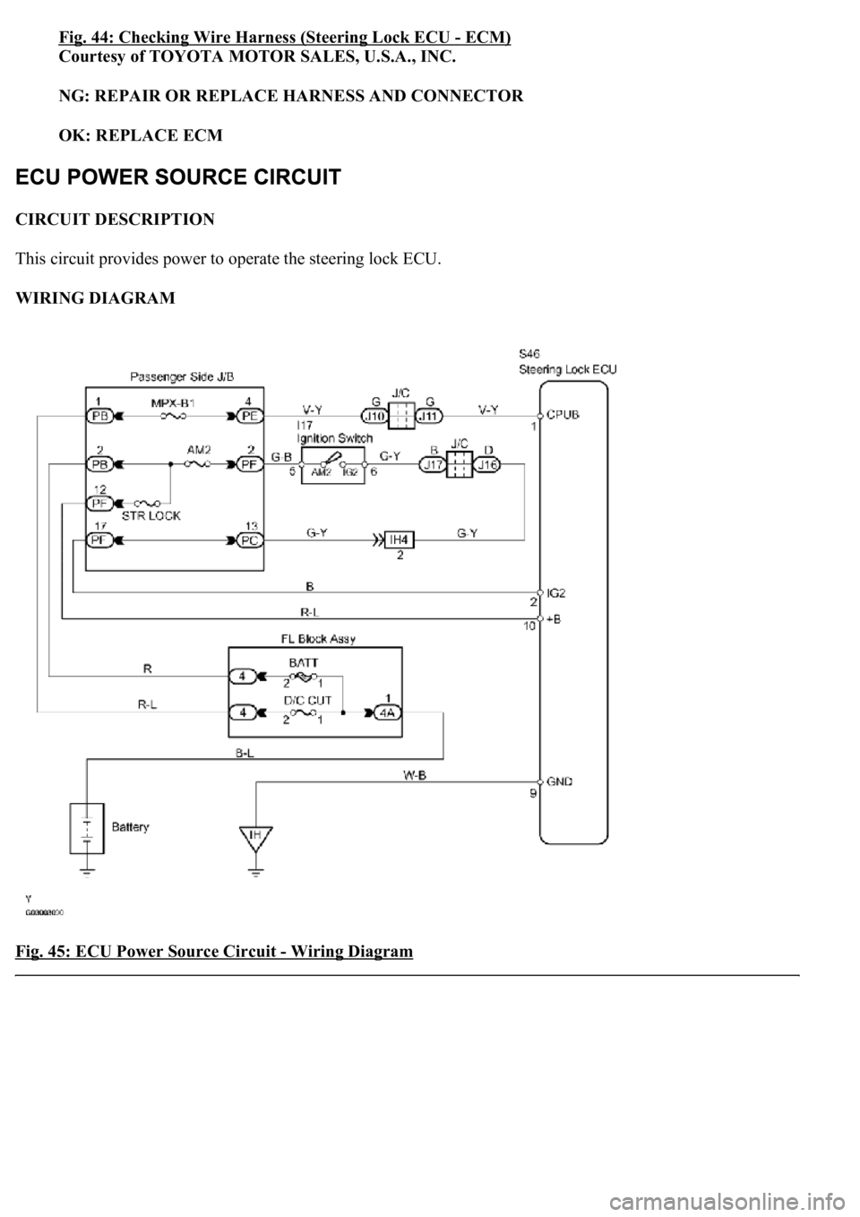
Fig. 44: Checking Wire Harness (Steering Lock ECU -ECM)
Courtesy of TOYOTA MOTOR SALES, U.S.A., INC.
NG: REPAIR OR REPLACE HARNESS AND CONNECTOR
OK: REPLACE ECM
CIRCUIT DESCRIPTION
This circuit provides power to operate the steering lock ECU.
WIRING DIAGRAM
Fig. 45: ECU Power Source Circuit
- Wiring Diagram
Page 3314 of 4500
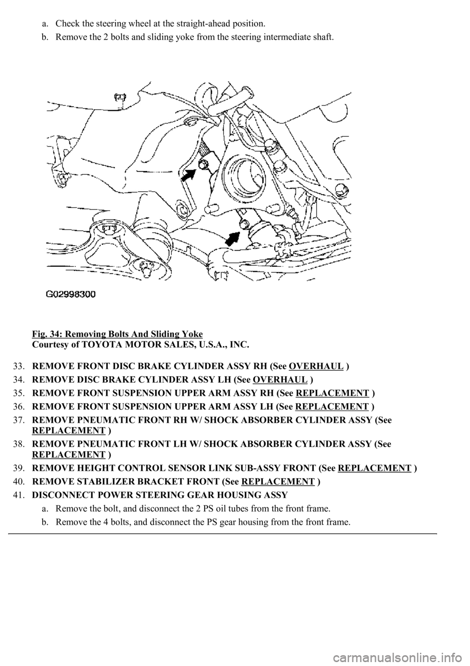
a. Check the steering wheel at the straight-ahead position.
b. Remove the 2 bolts and sliding yoke from the steering intermediate shaft.
Fig. 34: Removing Bolts And Sliding Yoke
Courtesy of TOYOTA MOTOR SALES, U.S.A., INC.
33.REMOVE FRONT DISC BRAKE CYLINDER ASSY RH (See OVERHAUL
)
34.REMOVE DISC BRAKE CYLINDER ASSY LH (See OVERHAUL
)
35.REMOVE FRONT SUSPENSION UPPER ARM ASSY RH (See REPLACEMENT
)
36.REMOVE FRONT SUSPENSION UPPER ARM ASSY LH (See REPLACEMENT
)
37.REMOVE PNEUMATIC FRONT RH W/ SHOCK ABSORBER CYLINDER ASSY (See
REPLACEMENT
)
38.REMOVE PNEUMATIC FRONT LH W/ SHOCK ABSORBER CYLINDER ASSY (See
REPLACEMENT
)
39.REMOVE HEIGHT CONTROL SENSOR LINK SUB-ASSY FRONT (See REPLACEMENT
)
40.REMOVE STABILIZER BRACKET FRONT (See REPLACEMENT
)
41.DISCONNECT POWER STEERING GEAR HOUSING ASSY
a. Remove the bolt, and disconnect the 2 PS oil tubes from the front frame.
b. Remove the 4 bolts, and disconnect the PS gear housing from the front frame.
Page 3356 of 4500
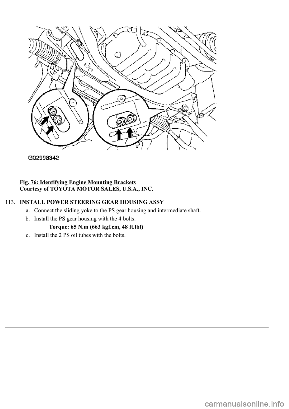
Fig. 76: Identifying Engine Mounting Brackets
Courtesy of TOYOTA MOTOR SALES, U.S.A., INC.
113.INSTALL POWER STEERING GEAR HOUSING ASSY
a. Connect the sliding yoke to the PS gear housing and intermediate shaft.
b. Install the PS gear housing with the 4 bolts.
Torque: 65 N.m (663 kgf.cm, 48 ft.lbf)
c. Install the 2 PS oil tubes with the bolts.