Page 2744 of 4500
Fig. 60: DTCs P0710, P0712, P0713 - Wiring Diagram
Courtesy of TOYOTA MOTOR SALES, U.S.A., INC.
INSPECTION PROCEDURE
HINT:
According to the DATA LIST displayed by the hand-held tester, you can read the value of the switch, sensor
actuator and so on without parts removal. Reading the DATA LIST as the first step of troubleshooting is one
method to shorten labor time.
a. Warm up the engine.
b. Turn the ignition switch off.
c. Connect the hand-held tester together with the CAN VIM (controller area network vehicle interface
module) to the DLC3.
d. Turn the ignition switch to the ON position.
e. Push the "ON" button of the hand-held tester.
f. Select the item "DIAGNOSIS/ENHANCED OBD II/DATA LIST".
g. According to the display on tester, read the "DATA LIST".
Page 2749 of 4500

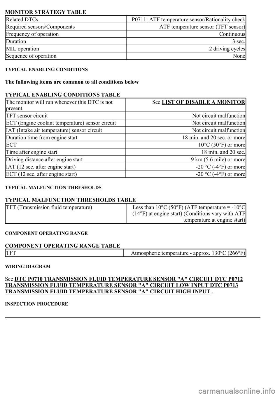
MONITOR STRATEGY TABLE
TYPICAL ENABLING CONDITIONS
The following items are common to all conditions below
TYPICAL ENABLING CONDITIONS TABLE
TYPICAL MALFUNCTION THRESHOLDS
TYPICAL MALFUNCTION THRESHOLDS TABLE
COMPONENT OPERATING RANGE
COMPONENT OPERATING RANGE TABLE
WIRING DIAGRAM
See DTC P0710 TRANSMISSION FLUID TEMPERATURE SENSOR "A" CIRCUIT DTC P0712
TRANSMISSION FLUID TEMPERATURE SENSOR "A" CIRCUIT LOW INPUT DTC P0713
TRANSMISSION FLUID TEMPERATURE SENSOR "A" CIRCUIT HIGH INPUT .
INSPECTION PROCEDURE
Related DTCsP0711: ATF temperature sensor/Rationality check
Required sensors/ComponentsATF temperature sensor (TFT sensor)
Frequency of operationContinuous
Duration3 sec.
MIL operation2 driving cycles
Sequence of operationNone
The monitor will run whenever this DTC is not
present.See LIST OF DISABLE A MONITOR
TFT sensor circuitNot circuit malfunction
ECT (Engine coolant temperature) sensor circuitNot circuit malfunction
IAT (Intake air temperature) sensor circuitNot circuit malfunction
Duration time from engine start18 min. and 20 sec. or more
ECT10°C (50°F) or more
Time after engine start18 min. and 20 sec.
Driving distance after engine start9 km (5.6 mile) or more
IAT (12 sec. after engine start)-20 °C (-4°F) or more
ECT (12 sec. after engine start)-20 °C (-4°F) or more
TFT (Transmission fluid temperature)Less than 10°C (50°F) (ATF temperature = -10°C
(14°F) at engine start) (Conditions vary with ATF
temperature at engine start)
TFTAtmospheric temperature - approx. 130°C (266°F)
Page 2754 of 4500
MONITOR STRATEGY
MONITOR STRATEGY TABLE
TYPICAL ENABLING CONDITIONS
TYPICAL ENABLING CONDITIONS TABLE
TYPICAL MALFUNCTION THRESHOLDS
TYPICAL MALFUNCTION THRESHOLDS TABLE
COMPONENT OPERATING RANGE
COMPONENT OPERATING RANGE TABLE
WIRING DIAGRAM
Related DTCsP0717: Speed sensor (NT)/Verify pulse input
Required sensors/ComponentsSpeed sensor (NT)
Frequency of operationContinuous
Duration5 sec.
MIL operationImmediate
Sequence of operationNone
The monitor will run whenever this DTC is not
present.See LIST OF DISABLE A MONITOR
Shift changeShift change is completed and before starting next
shift change operation
ECM selected gear4th, 5th or 6th
Output shaft rpm1,000 rpm or more
NSW switchOFF
R switchOFF
EngineRunning
Sensor signal rpmLess than 300 rpm
Speed sensor (NT)Input speed is equal to engine speed when lock-up
ON.
Page 2755 of 4500
Fig. 71: DTC P0717 - Wiring Diagram
Courtesy of TOYOTA MOTOR SALES, U.S.A., INC.
INSPECTION PROCEDURE
HINT:
According to the DATA LIST displayed by the hand-held tester, you can read the value of the switch, sensor,
actuator and so on without parts removal. Reading the DATA LIST as the first step of troubleshooting is one
method to shorten labor time.
a. Warm up the engine.
b. Turn the ignition switch off.
c. Connect the hand-held tester together with the CAN VIM (controller area network vehicle interface
module) to the DLC3.
d. Turn the ignition switch to the ON position.
e. Push the "ON" button of the hand-held tester.
f. Select the item "DIAGNOSIS/ENHANCED OBD II/DATA LIST".
g. According to the display on tester, read the "DATA LIST".
Fig. 72: Test Item Reference Chart
Courtesy of TOYOTA MOTOR SALES, U.S.A., INC.
HINT:
Page 2760 of 4500

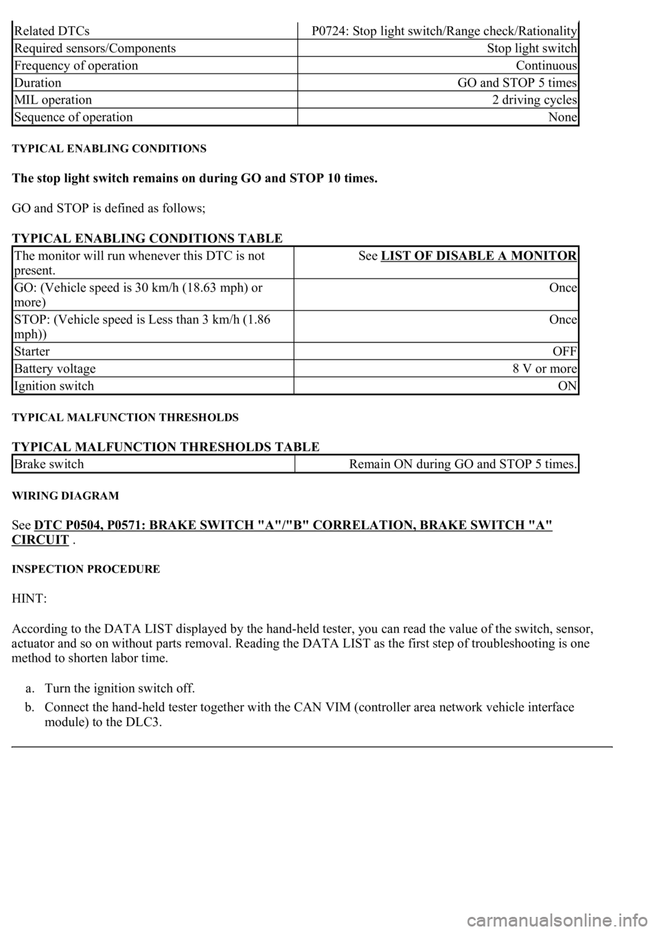
TYPICAL ENABLING CONDITIONS
The stop light switch remains on during GO and STOP 10 times.
GO and STOP is defined as follows;
TYPICAL ENABLING CONDITIONS TABLE
TYPICAL MALFUNCTION THRESHOLDS
TYPICAL MALFUNCTION THRESHOLDS TABLE
WIRING DIAGRAM
See DTC P0504, P0571: BRAKE SWITCH "A"/"B" CORRELATION, BRAKE SWITCH "A"
CIRCUIT .
INSPECTION PROCEDURE
HINT:
According to the DATA LIST displayed by the hand-held tester, you can read the value of the switch, sensor,
actuator and so on without parts removal. Reading the DATA LIST as the first step of troubleshooting is one
method to shorten labor time.
a. Turn the ignition switch off.
b. Connect the hand-held tester together with the CAN VIM (controller area network vehicle interface
module) to the DLC3.
Related DTCsP0724: Stop light switch/Range check/Rationality
Required sensors/ComponentsStop light switch
Frequency of operationContinuous
DurationGO and STOP 5 times
MIL operation2 driving cycles
Sequence of operationNone
The monitor will run whenever this DTC is not
present.See LIST OF DISABLE A MONITOR
GO: (Vehicle speed is 30 km/h (18.63 mph) or
more)Once
STOP: (Vehicle speed is Less than 3 km/h (1.86
mph))Once
StarterOFF
Battery voltage8 V or more
Ignition switchON
Brake switchRemain ON during GO and STOP 5 times.
Page 2771 of 4500
TYPICAL MALFUNCTION THRESHOLDS TABLE
COMPONENT OPERATING RANGE
COMPONENT OPERATING RANGE TABLE
WIRING DIAGRAM
Fig. 89: DTC P0748 - Wiring Diagram
Courtesy of TOYOTA MOTOR SALES, U.S.A., INC.
INSPECTION PROCEDURE
HINT:
The shift solenoid valve SL1 is turned on/off normally when the shift lever is in the D position:
GEARSHIFT SPECIFICATION TABLE
1.INSPECT TRANSMISSION WIRE (SL1)
a. Disconnect the transmission wire connector from the transmission.
b. Measure the resistance according to the value(s) in the table below.
Standard:
Output signal duty100%
Output signal dutyLess than 100%
ECM
command
gearshift
1st2nd3rd4th5th6th
Shift solenoid
valve SL1OFFOFFOFFOFFONON
Page 2813 of 4500
COMPONENT OPERATING RANGE
COMPONENT OPERATING RANGE TABLE
WIRING DIAGRAM
Fig. 120: DTC P0778 - Wiring Diagram
Courtesy of TOYOTA MOTOR SALES, U.S.A., INC.
INSPECTION PROCEDURE
HINT:
The shift solenoid valve SL2 is turned on/off normally when the shift lever is in the D position:
GEARSHIFT SPECIFICATION TABLE
1.INSPECT TRANSMISSION WIRE (SL2)
a. Disconnect the transmission wire connector from the transmission.
b. Measure the resistance according to the value(s) in the table below.
Output signal duty100%
Output signal dutyLess than 100%
ECM
command
gearshift
1st2nd3rd4th5th6th
Shift solenoid
valve SL2ONONONONOFFOFF
Page 2828 of 4500
P0974: Range check (High resistance)
TYPICAL ENABLING CONDITIONS TABLE - P0974
TYPICAL MALFUNCTION THRESHOLDS
P0973: Range check (Low resistance)
TYPICAL MALFUNCTION THRESHOLDS - P0973
P0974: Range check (High resistance)
TYPICAL MALFUNCTION THRESHOLDS TABLE - P0974
COMPONENT OPERATING RANGE
COMPONENT OPERATING RANGE TABLE
WIRING DIAGRAM
Fig. 134: DTC P0973, P0974 - Wiring Diagram
Courtesy of TOYOTA MOTOR SALES, U.S.A., INC.
INSPECTION PROCEDURE
Shift solenoid valve S1ON
The monitor will run whenever this DTC is not
present.See LIST OF DISABLE A MONITOR
Shift solenoid valve S1OFF
Shift solenoid valve S1 resistance8 ohms or less
Shift solenoid valve S1 resistance100 kohms or more
Shift solenoid valve S1Resistance: 11 to 15 ohms at 20°C (68°F)