2003 LEXUS LS430 rear seat back
[x] Cancel search: rear seat backPage 1596 of 4500
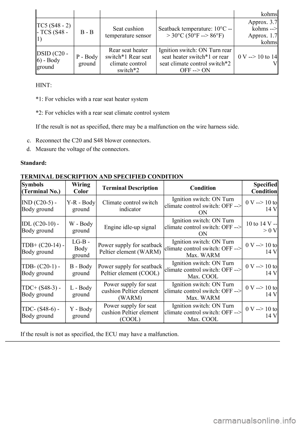
HINT:
*1: For vehicles with a rear seat heater system
*2: For vehicles with a rear seat climate control system
If the result is not as specified, there may be a malfunction on the wire harness side.
c. Reconnect the C20 and S48 blower connectors.
d. Measure the voltage of the connectors.
Standard:
TERMINAL DESCRIPTION AND SPECIFIED CONDITION
If the result is not as specified, the ECU ma
y have a malfunction.
kohms
TC5 (S48 - 2)
- TCS (S48 -
1)
B - BSeat cushion
temperature sensorSeatback temperature: 10°C --
> 30°C (50°F --> 86°F)
Approx. 3.7
kohms -->
Approx. 1.7
kohms
DSID (C20 -
6) - Body
groundP - Body
ground
Rear seat heater
switch*1 Rear seat
climate control
switch*2Ignition switch: ON Turn rear
seat heater switch*1 or rear
seat climate control switch*2
OFF --> ON
0 V --> 10 to 14
V
Symbols
(Terminal No.)Wiring
ColorTerminal DescriptionConditionSpecified
Condition
IND (C20-5) -
Body groundY-R - Body
groundClimate control switch
indicatorIgnition switch: ON Turn
climate control switch: OFF -->
ON0 V --> 10 to
14 V
IDL (C20-10) -
Body groundW - Body
groundEngine idle-up signal
Ignition switch: ON Turn
climate control switch: OFF -->
ON10 to 14 V --
> 0 V
TDB+ (C20-14) -
Body groundLG-B -
Body
groundPower supply for seatback
Peltier element (WARM)Ignition switch: ON Turn
climate control switch: OFF -->
Max. WARM0 V --> 10 to
14 V
TDB- (C20-1) -
Body groundB - Body
groundPower supply for seatback
Peltier element (COOL)Ignition switch: ON Turn
climate control switch: OFF -->
Max. COOL0 V --> 10 to
14 V
TDC+ (S48-3) -
Body groundL - Body
groundPower supply for seat
cushion Peltier element
(WARM)Ignition switch: ON Turn
climate control switch: OFF -->
Max. WARM0 V --> 10 to
14 V
TDC- (S48-6) -
Body groundY - Body
groundPower supply for seat
cushion Peltier element
(COOL)Ignition switch: ON Turn
climate control switch: OFF -->
Max. COOL0 V --> 10 to
14 V
Page 1598 of 4500
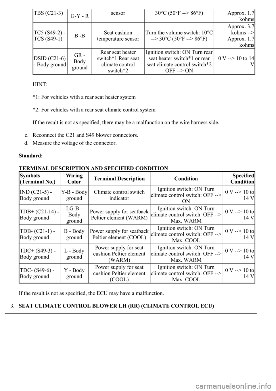
HINT:
*1: For vehicles with a rear seat heater system
*2: For vehicles with a rear seat climate control system
If the result is not as specified, there may be a malfunction on the wire harness side.
c. Reconnect the C21 and S49 blower connectors.
d. Measure the voltage of the connector.
Standard:
TERMINAL DESCRIPTION AND SPECIFIED CONDITION
If the result is not as specified, the ECU may have a malfunction.
3.SEAT CLIMATE CONTROL BLOWER LH (RR) (CLIMATE CONTROL ECU)
TBS (C21-3)G-Y - Rsensor30°C (50°F --> 86°F)Approx. 1.7
kohms
TC5 (S49-2) -
TCS (S49-1)B -BSeat cushion
temperature sensorTurn the volume switch: 10°C
--> 30°C (50°F --> 86°F)
Approx. 3.7
kohms -->
Approx. 1.7
kohms
DSID (C21-6)
- Body groundGR -
Body
groundRear seat heater
switch*1 Rear seat
climate control
switch*2Ignition switch: ON Turn rear
seat heater switch*1 or rear
seat climate control switch*2
OFF --> ON
0 V --> 10 to 14
V
Symbols
(Terminal No.)Wiring
ColorTerminal DescriptionConditionSpecified
Condition
IND (C21-5) -
Body groundY-B - Body
groundClimate control switch
indicatorIgnition switch: ON Turn
climate control switch: OFF -->
ON0 V --> 10 to
14 V
TDB+ (C21-14) -
Body groundLG-B -
Body
groundPower supply for seatback
Peltier element (WARM)Ignition switch: ON Turn
climate control switch: OFF -->
Max. WARM0 V --> 10 to
14 V
TDB- (C21-1) -
Body groundB - Body
groundPower supply for seatback
Peltier element (COOL)Ignition switch: ON Turn
climate control switch: OFF -->
Max. COOL0 V --> 10 to
14 V
TDC+ (S49-3) -
Body groundL - Body
groundPower supply for seat
cushion Peltier element
(WARM)Ignition switch: ON Turn
climate control switch: OFF -->
Max. WARM0 V --> 10 to
14 V
TDC- (S49-6) -
Body groundY - Body
groundPower supply for seat
cushion Peltier element
(COOL)Ignition switch: ON Turn
climate control switch: OFF -->
Max. COOL0 V --> 10 to
14 V
Page 1599 of 4500
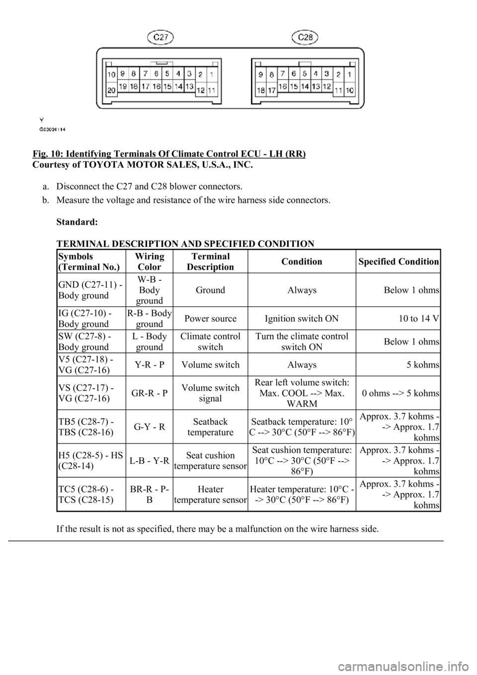
Fig. 10: Identifying Terminals Of Climate Control ECU - LH (RR)
Courtesy of TOYOTA MOTOR SALES, U.S.A., INC.
a. Disconnect the C27 and C28 blower connectors.
b. Measure the voltage and resistance of the wire harness side connectors.
Standard:
TERMINAL DESCRIPTION AND SPECIFIED CONDITION
If the result is not as specified, there ma
y be a malfunction on the wire harness side.
Symbols
(Terminal No.)Wiring
ColorTerminal
DescriptionConditionSpecified Condition
GND (C27-11) -
Body groundW-B -
Body
ground
GroundAlwaysBelow 1 ohms
IG (C27-10) -
Body groundR-B - Body
groundPower sourceIgnition switch ON10 to 14 V
SW (C27-8) -
Body groundL - Body
groundClimate control
switchTurn the climate control
switch ONBelow 1 ohms
V5 (C27-18) -
VG (C27-16)Y-R - PVolume switchAlways5 kohms
VS (C27-17) -
VG (C27-16)GR-R - PVolume switch
signalRear left volume switch:
Max. COOL --> Max.
WARM
0 ohms --> 5 kohms
TB5 (C28-7) -
TBS (C28-16)G-Y - RSeatback
temperatureSeatback temperature: 10°
C --> 30°C (50°F --> 86°F)Approx. 3.7 kohms -
-> Approx. 1.7
kohms
H5 (C28-5) - HS
(C28-14)L-B - Y-RSeat cushion
temperature sensorSeat cushion temperature:
10°C --> 30°C (50°F -->
86°F)Approx. 3.7 kohms -
-> Approx. 1.7
kohms
TC5 (C28-6) -
TCS (C28-15)BR-R - P-
BHeater
temperature sensorHeater temperature: 10°C -
-> 30°C (50°F --> 86°F)Approx. 3.7 kohms -
-> Approx. 1.7
kohms
Page 1600 of 4500
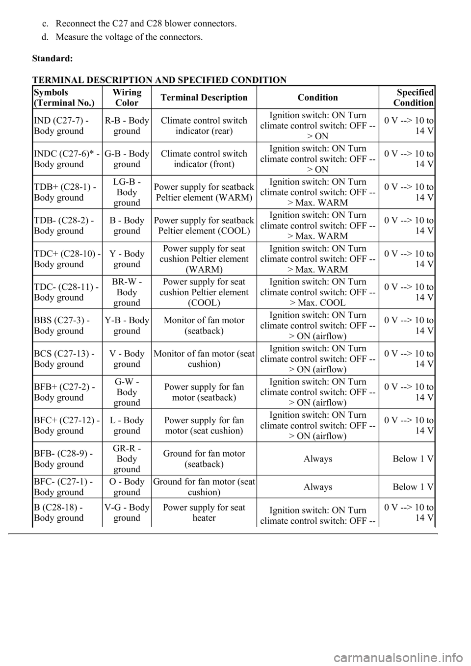
c. Reconnect the C27 and C28 blower connectors.
d. Measure the voltage of the connectors.
Standard:
TERMINAL DESCRIPTION AND SPECIFIED CONDITION
Symbols
(Terminal No.)Wiring
ColorTerminal DescriptionConditionSpecified
Condition
IND (C27-7) -
Body groundR-B - Body
groundClimate control switch
indicator (rear)Ignition switch: ON Turn
climate control switch: OFF --
> ON0 V --> 10 to
14 V
INDC (C27-6)* -
Body groundG-B - Body
groundClimate control switch
indicator (front)Ignition switch: ON Turn
climate control switch: OFF --
> ON0 V --> 10 to
14 V
TDB+ (C28-1) -
Body groundLG-B -
Body
groundPower supply for seatback
Peltier element (WARM)Ignition switch: ON Turn
climate control switch: OFF --
> Max. WARM0 V --> 10 to
14 V
TDB- (C28-2) -
Body groundB - Body
groundPower supply for seatback
Peltier element (COOL)Ignition switch: ON Turn
climate control switch: OFF --
> Max. WARM0 V --> 10 to
14 V
TDC+ (C28-10) -
Body groundY - Body
groundPower supply for seat
cushion Peltier element
(WARM)Ignition switch: ON Turn
climate control switch: OFF --
> Max. WARM0 V --> 10 to
14 V
TDC- (C28-11) -
Body groundBR-W -
Body
groundPower supply for seat
cushion Peltier element
(COOL)Ignition switch: ON Turn
climate control switch: OFF --
> Max. COOL0 V --> 10 to
14 V
BBS (C27-3) -
Body groundY-B - Body
groundMonitor of fan motor
(seatback)Ignition switch: ON Turn
climate control switch: OFF --
> ON (airflow)0 V --> 10 to
14 V
BCS (C27-13) -
Body groundV - Body
groundMonitor of fan motor (seat
cushion)Ignition switch: ON Turn
climate control switch: OFF --
> ON (airflow)0 V --> 10 to
14 V
BFB+ (C27-2) -
Body groundG-W -
Body
groundPower supply for fan
motor (seatback)Ignition switch: ON Turn
climate control switch: OFF --
> ON (airflow)0 V --> 10 to
14 V
BFC+ (C27-12) -
Body groundL - Body
groundPower supply for fan
motor (seat cushion)Ignition switch: ON Turn
climate control switch: OFF --
> ON (airflow)0 V --> 10 to
14 V
BFB- (C28-9) -
Body groundGR-R -
Body
groundGround for fan motor
(seatback)AlwaysBelow 1 V
BFC- (C27-1) -
Body groundO - Body
groundGround for fan motor (seat
cushion)AlwaysBelow 1 V
B (C28-18) -
Body groundV-G - Body
groundPower supply for seat
heaterIgnition switch: ON Turn
climate control switch: OFF --0 V --> 10 to
14 V
Page 1602 of 4500
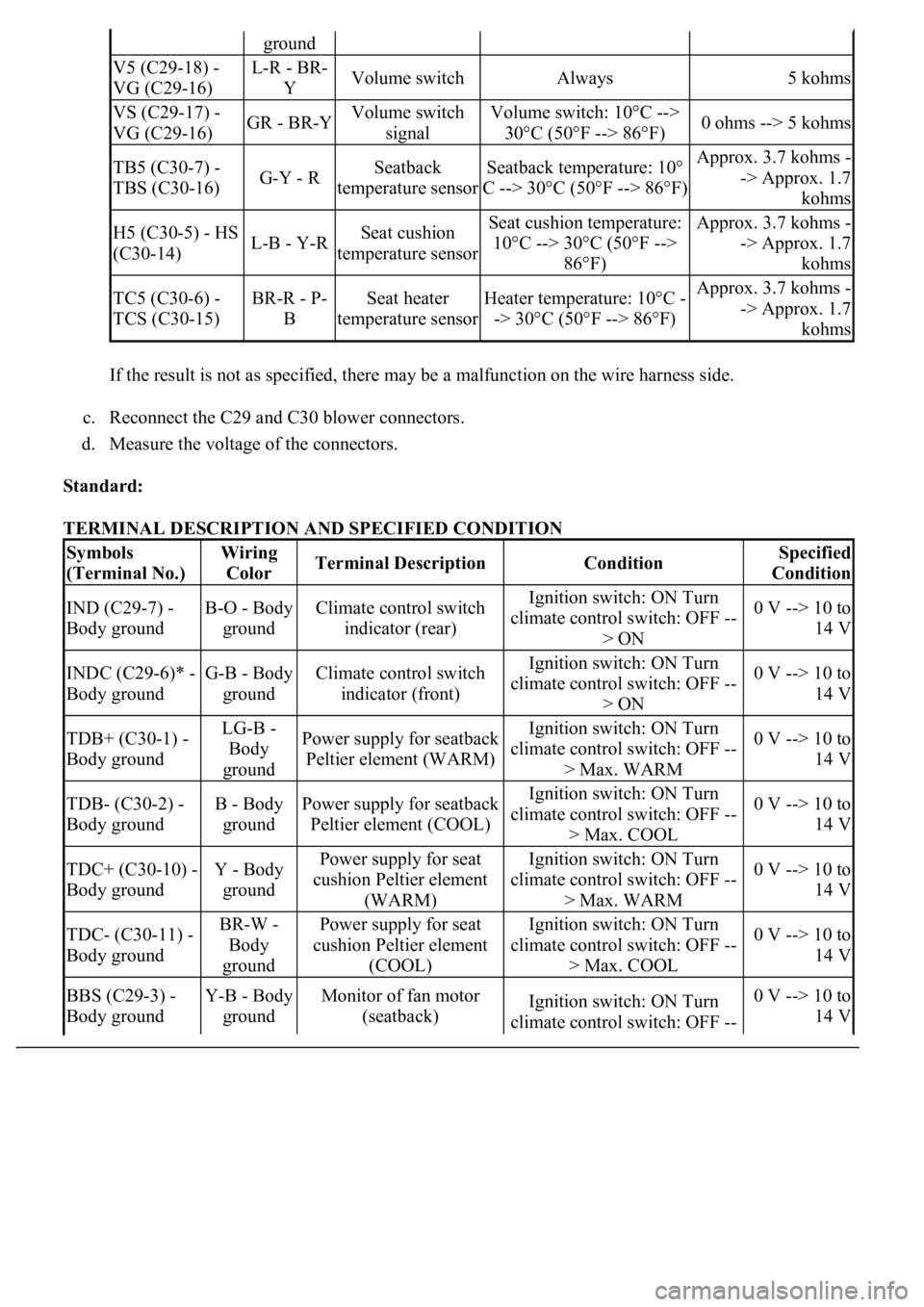
If the result is not as specified, there may be a malfunction on the wire harness side.
c. Reconnect the C29 and C30 blower connectors.
d. Measure the voltage of the connectors.
Standard:
TERMINAL DESCRIPTION AND SPECIFIED CONDITION
ground
V5 (C29-18) -
VG (C29-16)L-R - BR-
YVolume switchAlways5 kohms
VS (C29-17) -
VG (C29-16)GR - BR-YVolume switch
signalVolume switch: 10°C -->
30°C (50°F --> 86°F)0 ohms --> 5 kohms
TB5 (C30-7) -
TBS (C30-16)G-Y - RSeatback
temperature sensorSeatback temperature: 10°
C --> 30°C (50°F --> 86°F)Approx. 3.7 kohms -
-> Approx. 1.7
kohms
H5 (C30-5) - HS
(C30-14)L-B - Y-RSeat cushion
temperature sensorSeat cushion temperature:
10°C --> 30°C (50°F -->
86°F)Approx. 3.7 kohms -
-> Approx. 1.7
kohms
TC5 (C30-6) -
TCS (C30-15)BR-R - P-
BSeat heater
temperature sensorHeater temperature: 10°C -
-> 30°C (50°F --> 86°F)Approx. 3.7 kohms -
-> Approx. 1.7
kohms
Symbols
(Terminal No.)Wiring
ColorTerminal DescriptionConditionSpecified
Condition
IND (C29-7) -
Body groundB-O - Body
groundClimate control switch
indicator (rear)Ignition switch: ON Turn
climate control switch: OFF --
> ON0 V --> 10 to
14 V
INDC (C29-6)* -
Body groundG-B - Body
groundClimate control switch
indicator (front)Ignition switch: ON Turn
climate control switch: OFF --
> ON0 V --> 10 to
14 V
TDB+ (C30-1) -
Body groundLG-B -
Body
groundPower supply for seatback
Peltier element (WARM)Ignition switch: ON Turn
climate control switch: OFF --
> Max. WARM0 V --> 10 to
14 V
TDB- (C30-2) -
Body groundB - Body
groundPower supply for seatback
Peltier element (COOL)Ignition switch: ON Turn
climate control switch: OFF --
> Max. COOL0 V --> 10 to
14 V
TDC+ (C30-10) -
Body groundY - Body
groundPower supply for seat
cushion Peltier element
(WARM)Ignition switch: ON Turn
climate control switch: OFF --
> Max. WARM0 V --> 10 to
14 V
TDC- (C30-11) -
Body groundBR-W -
Body
groundPower supply for seat
cushion Peltier element
(COOL)Ignition switch: ON Turn
climate control switch: OFF --
> Max. COOL0 V --> 10 to
14 V
BBS (C29-3) -
Body groundY-B - Body
groundMonitor of fan motor
(seatback)Ignition switch: ON Turn
climate control switch: OFF --0 V --> 10 to
14 V
Page 1611 of 4500
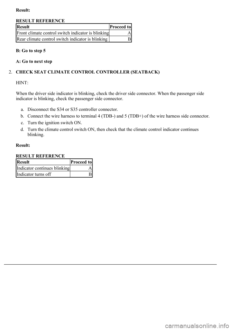
Result:
RESULT REFERENCE
B: Go to step 5
A: Go to next step
2.CHECK SEAT CLIMATE CONTROL CONTROLLER (SEATBACK)
HINT:
When the driver side indicator is blinking, check the driver side connector. When the passenger side
indicator is blinking, check the passenger side connector.
a. Disconnect the S34 or S35 controller connector.
b. Connect the wire harness to terminal 4 (TDB-) and 5 (TDB+) of the wire harness side connector.
c. Turn the ignition switch ON.
d. Turn the climate control switch ON, then check that the climate control indicator continues
blinking.
Result:
RESULT REFERENCE
ResultProceed to
Front climate control switch indicator is blinkingA
Rear climate control switch indicator is blinkingB
ResultProceed to
Indicator continues blinkingA
Indicator turns offB
Page 1616 of 4500
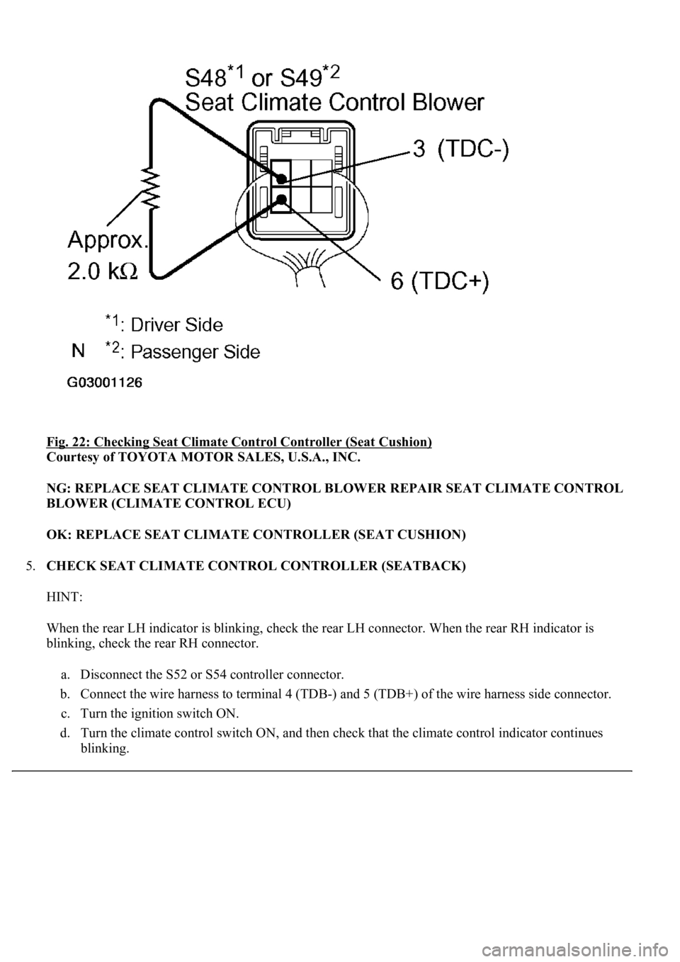
<0029004c004a0011000300150015001d00030026004b00480046004e004c0051004a0003003600480044005700030026004f004c00500044005700480003002600520051005700550052004f0003002600520051005700550052004f004f00480055000300
0b00360048004400570003002600580056004b004c00520051[)
Courtesy of TOYOTA MOTOR SALES, U.S.A., INC.
NG: REPLACE SEAT CLIMATE CONTROL BLOWER REPAIR SEAT CLIMATE CONTROL
BLOWER (CLIMATE CONTROL ECU)
OK: REPLACE SEAT CLIMATE CONTROLLER (SEAT CUSHION)
5.CHECK SEAT CLIMATE CONTROL CONTROLLER (SEATBACK)
HINT:
When the rear LH indicator is blinking, check the rear LH connector. When the rear RH indicator is
blinking, check the rear RH connector.
a. Disconnect the S52 or S54 controller connector.
b. Connect the wire harness to terminal 4 (TDB-) and 5 (TDB+) of the wire harness side connector.
c. Turn the ignition switch ON.
d. Turn the climate control switch ON, and then check that the climate control indicator continues
blinking.
Page 1617 of 4500
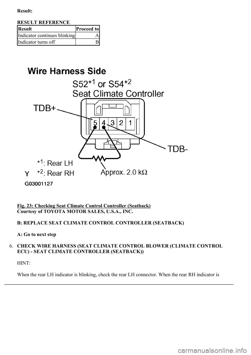
Result:
RESULT REFERENCE
Fig. 23: Checking Seat Climate Control Controller (Seatback)
Courtesy of TOYOTA MOTOR SALES, U.S.A., INC.
B: REPLACE SEAT CLIMATE CONTROL CONTROLLER (SEATBACK)
A: Go to next step
6.CHECK WIRE HARNESS (SEAT CLIMATE CONTROL BLOWER (CLIMATE CONTROL
ECU) - SEAT CLIMATE CONTROLLER (SEATBACK))
HINT:
When the rear LH indicator is blinkin
g, check the rear LH connector. When the rear RH indicator is
ResultProceed to
Indicator continues blinkingA
Indicator turns offB