Page 922 of 4500

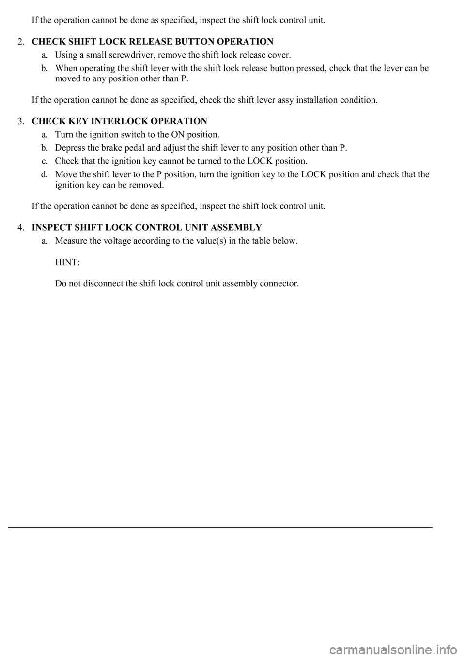
If the operation cannot be done as specified, inspect the shift lock control unit.
2.CHECK SHIFT LOCK RELEASE BUTTON OPERATION
a. Using a small screwdriver, remove the shift lock release cover.
b. When operating the shift lever with the shift lock release button pressed, check that the lever can be
moved to any position other than P.
If the operation cannot be done as specified, check the shift lever assy installation condition.
3.CHECK KEY INTERLOCK OPERATION
a. Turn the ignition switch to the ON position.
b. Depress the brake pedal and adjust the shift lever to any position other than P.
c. Check that the ignition key cannot be turned to the LOCK position.
d. Move the shift lever to the P position, turn the ignition key to the LOCK position and check that the
ignition key can be removed.
If the operation cannot be done as specified, inspect the shift lock control unit.
4.INSPECT SHIFT LOCK CONTROL UNIT ASSEMBLY
a. Measure the voltage according to the value(s) in the table below.
HINT:
Do not disconnect the shift lock control unit assembl
y connector.
Page 929 of 4500

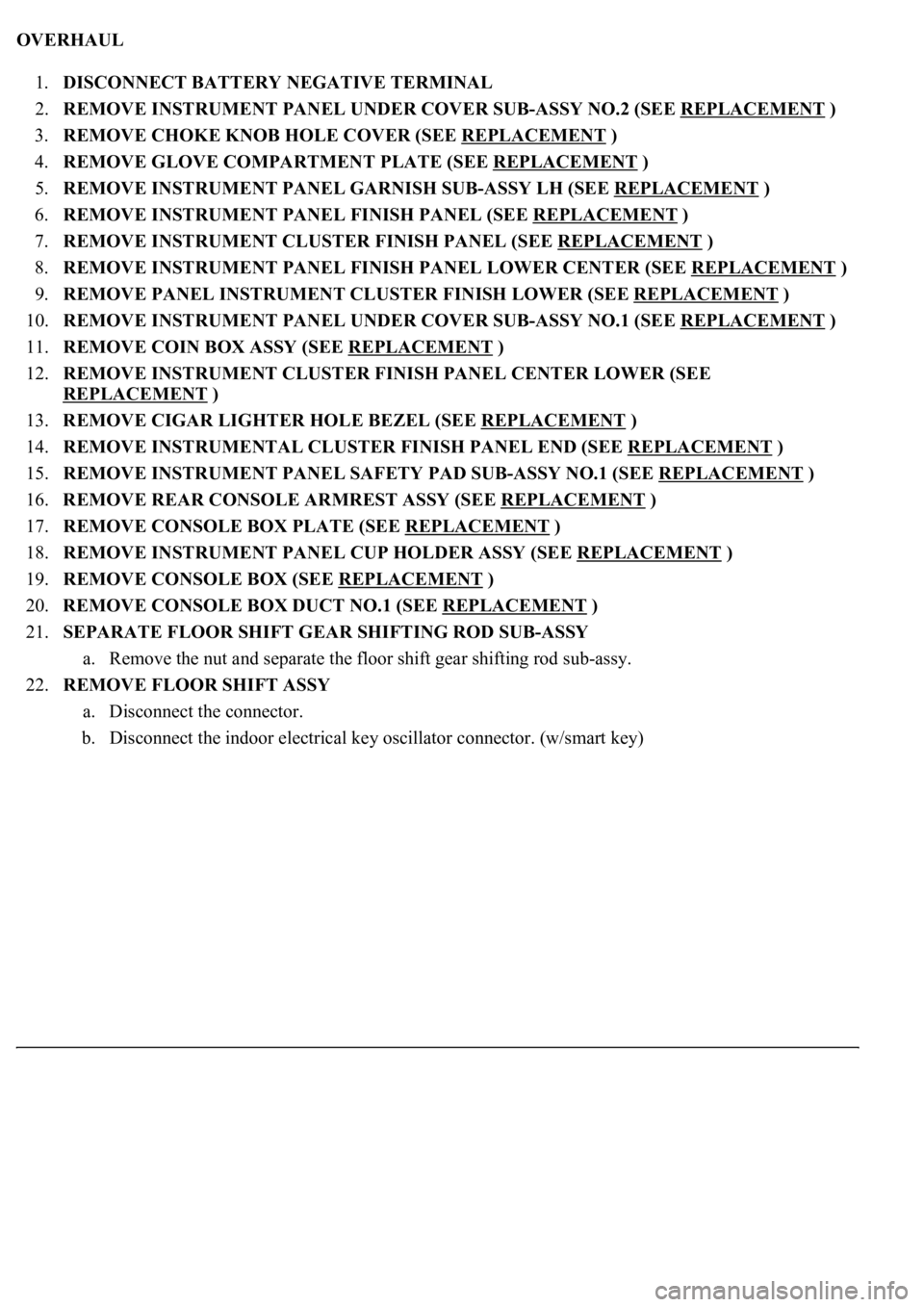
OVERHAUL
1.DISCONNECT BATTERY NEGATIVE TERMINAL
2.REMOVE INSTRUMENT PANEL UNDER COVER SUB-ASSY NO.2 (SEE REPLACEMENT
)
3.REMOVE CHOKE KNOB HOLE COVER (SEE REPLACEMENT
)
4.REMOVE GLOVE COMPARTMENT PLATE (SEE REPLACEMENT
)
5.REMOVE INSTRUMENT PANEL GARNISH SUB-ASSY LH (SEE REPLACEMENT
)
6.REMOVE INSTRUMENT PANEL FINISH PANEL (SEE REPLACEMENT
)
7.REMOVE INSTRUMENT CLUSTER FINISH PANEL (SEE REPLACEMENT
)
8.REMOVE INSTRUMENT PANEL FINISH PANEL LOWER CENTER (SEE REPLACEMENT
)
9.REMOVE PANEL INSTRUMENT CLUSTER FINISH LOWER (SEE REPLACEMENT
)
10.REMOVE INSTRUMENT PANEL UNDER COVER SUB-ASSY NO.1 (SEE REPLACEMENT
)
11.REMOVE COIN BOX ASSY (SEE REPLACEMENT
)
12.REMOVE INSTRUMENT CLUSTER FINISH PANEL CENTER LOWER (SEE
REPLACEMENT
)
13.REMOVE CIGAR LIGHTER HOLE BEZEL (SEE REPLACEMENT
)
14.REMOVE INSTRUMENTAL CLUSTER FINISH PANEL END (SEE REPLACEMENT
)
15.REMOVE INSTRUMENT PANEL SAFETY PAD SUB-ASSY NO.1 (SEE REPLACEMENT
)
16.REMOVE REAR CONSOLE ARMREST ASSY (SEE REPLACEMENT
)
17.REMOVE CONSOLE BOX PLATE (SEE REPLACEMENT
)
18.REMOVE INSTRUMENT PANEL CUP HOLDER ASSY (SEE REPLACEMENT
)
19.REMOVE CONSOLE BOX (SEE REPLACEMENT
)
20.REMOVE CONSOLE BOX DUCT NO.1 (SEE REPLACEMENT
)
21.SEPARATE FLOOR SHIFT GEAR SHIFTING ROD SUB-ASSY
a. Remove the nut and separate the floor shift gear shifting rod sub-assy.
22.REMOVE FLOOR SHIFT ASSY
a. Disconnect the connector.
b. Disconnect the indoor electrical key oscillator connector. (w/smart key)
Page 931 of 4500
Fig. 106: Removing 4 Bolts
Courtesy of TOYOTA MOTOR SALES, U.S.A., INC.
23.REMOVE INDOOR ELECTRICALLY KEY OSCILLATOR (W/SMART KEY)
a. Remove the 2 screws, and then remove the indoor electrical key oscillator from the shift lever plate.
24.REMOVE SHIFT LOCK RELEASE BUTTON COVER
a. Using a small screwdriver, remove the shift lock release button cover.
25.REMOVE SHIFT LEVER KNOB SUB-ASSY
a. Remove the shift lever knob sub-assy.
Page 958 of 4500
Fig. 133: Installing Shift Lever Knob Sub-Assy To Floor Shift Lever Assy
Courtesy of TOYOTA MOTOR SALES, U.S.A., INC.
48.INSTALL INDOOR ELECTRICAL KEY OSCILLATOR (W/ SMART KEY)
a. Install the indoor electrical key oscillator to the shift lever plate with the 2 screws.
49.INSTALL FLOOR SHIFT ASSY
a. Install the floor shift assy with the 4 bolts.
Torque: 8.3 N.m (85 kgf.cm, 74 in.lbf)
b. Connect the connector to the floor shift assy.
Page 1517 of 4500

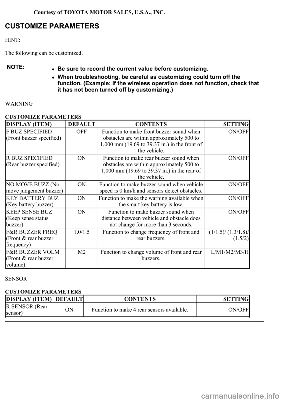
Courtesy of TOYOTA MOTOR SALES, U.S.A., INC.
HINT:
The following can be customized.
WARNING
CUSTOMIZE PARAMETERS
SENSOR
CUSTOMIZE PARAMETERS
DISPLAY (ITEM)DEFAULTCONTENTSSETTING
F BUZ SPECIFIED
(Front buzzer specified)OFFFunction to make front buzzer sound when
obstacles are within approximately 500 to
1,000 mm (19.69 to 39.37 in.) in the front of
the vehicle.ON/OFF
R BUZ SPECIFIED
(Rear buzzer specified)ONFunction to make rear buzzer sound when
obstacles are within approximately 500 to
1,000 mm (19.69 to 39.37 in.) in the rear of
the vehicle.ON/OFF
NO MOVE BUZZ (No
move judgement buzzer)ONFunction to make buzzer sound when vehicle
speed is 0 km/h and sensors detect obstacles.ON/OFF
KEY BATTERY BUZ
(Key battery buzzer)ONFunction to make the warning available when
the smart key battery is low.ON/OFF
KEEP SENSE BUZ
(Keep sense status
buzzer)ONFunction to make buzzer sound when
distance between vehicle and obstacle does
not change for more than 3 seconds.ON/OFF
F&R BUZZER FREQ
(Front & rear buzzer
frequency)1.0/1.5Function to change frequency of front and
rear buzzers.(1/1.5)/ (1.3/1.8)/
(1.5/2)
F&R BUZZER VOLM
(Front & rear buzzer
volume)M2Function to change volume of front and rear
buzzers.L/M1/M2/M3/H
DISPLAY (ITEM)DEFAULTCONTENTSSETTING
R SENSOR (Rear
sensor)ONFunction to make 4 rear sensors available.ON/OFF
Page 1749 of 4500
Courtesy of TOYOTA MOTOR SALES, U.S.A., INC.
Fig. 15: Warning Area Flow Chart (2 Of 2)
Courtesy of TOYOTA MOTOR SALES, U.S.A., INC.
Warning process:
The warning items can be scrolled automatically. (Unable to switch manually)
When any malfunction in the framed items is detected, a warning buzzer (a single sound)
sounds. It sounds only when the malfunction occurs for the first time. The item is displayed
along with the buzzer sounding.
The most current warning item is displayed first.
When two or more warning occur, they are displayed in turn at an interval of 2 seconds.
When a warnings occurs, the item is displayed for 6 seconds only the first time.
Smart Key System:
The buzzer in the smart key system is controlled by a signal from the security ECU.
HINT:
The buzzer sounds continuously if the item "Shift to P range" is displayed.
Oil Maintenance Display:
The items are displayed in accordance with the distance after reset (see ON-VEHICLE
Page 1782 of 4500

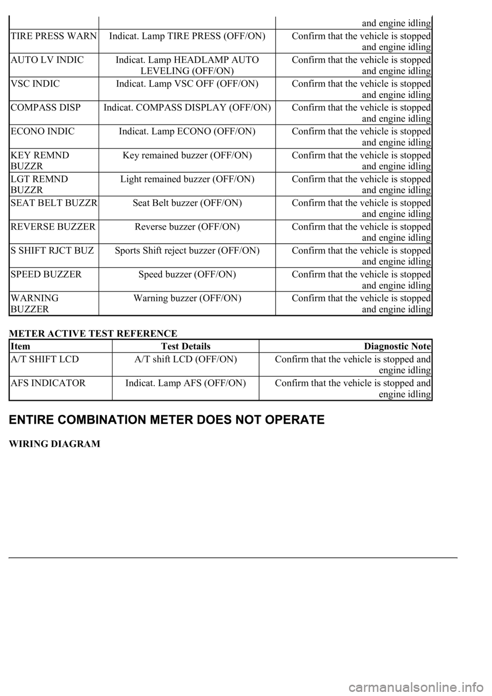
METER ACTIVE TEST REFERENCE
WIRING DIAGRAM
and engine idling
TIRE PRESS WARNIndicat. Lamp TIRE PRESS (OFF/ON)Confirm that the vehicle is stopped
and engine idling
AUTO LV INDICIndicat. Lamp HEADLAMP AUTO
LEVELING (OFF/ON)Confirm that the vehicle is stopped
and engine idling
VSC INDICIndicat. Lamp VSC OFF (OFF/ON)Confirm that the vehicle is stopped
and engine idling
COMPASS DISPIndicat. COMPASS DISPLAY (OFF/ON)Confirm that the vehicle is stopped
and engine idling
ECONO INDICIndicat. Lamp ECONO (OFF/ON)Confirm that the vehicle is stopped
and engine idling
KEY REMND
BUZZRKey remained buzzer (OFF/ON)Confirm that the vehicle is stopped
and engine idling
LGT REMND
BUZZRLight remained buzzer (OFF/ON)Confirm that the vehicle is stopped
and engine idling
SEAT BELT BUZZRSeat Belt buzzer (OFF/ON)Confirm that the vehicle is stopped
and engine idling
REVERSE BUZZERReverse buzzer (OFF/ON)Confirm that the vehicle is stopped
and engine idling
S SHIFT RJCT BUZSports Shift reject buzzer (OFF/ON)Confirm that the vehicle is stopped
and engine idling
SPEED BUZZERSpeed buzzer (OFF/ON)Confirm that the vehicle is stopped
and engine idling
WARNING
BUZZERWarning buzzer (OFF/ON)Confirm that the vehicle is stopped
and engine idling
ItemTest DetailsDiagnostic Note
A/T SHIFT LCDA/T shift LCD (OFF/ON)Confirm that the vehicle is stopped and
engine idling
AFS INDICATORIndicat. Lamp AFS (OFF/ON)Confirm that the vehicle is stopped and
engine idling
Page 1956 of 4500
c. Adjust the laser beam axis
1. Turn the ignition switch to the ON position.
2. Push the cruise control main switch ON-OFF button on.
3. Connect the hand-held tester to the DLC3, and turn the power ON.
Fig. 9: Connecting Hand
-Held Tester To DLC3
Courtesy of TOYOTA MOTOR SALES, U.S.A., INC.
4. Operate by following the screen menu and select "BEAM AXIS ADJUST" of the Laser Cruise
Control, then press the "ENTER" key.
HINT:
Pressing the "ENTER" key will make the ECM transfer to BEAM AXIS ADJUSTMENT
MODE.
When the ECM transfers to BEAM AXIS ADJUSTMENT MODE, the buzzer sounds for 1
second.