Page 268 of 4500
Standard:
A/C EVAPORATOR TEMPERATURE SENSOR RESISTANCE
<0029004c004a0011000300180013001d0003002c005100560053004800460057004c0051004a000300240012002600030028005900440053005200550044005700520055000300370048005000530048005500440057005800550048000300360048005100
5600520055[
Courtesy of TOYOTA MOTOR SALES, U.S.A., INC.
Tester connectionConditionSpecified condition
1 - 2-10°C (14°F)7.40 to 9.20 kohms
1 - 2-5°C (23°F)5.65 to 7.00 kohms
1 - 20°C (32°F)4.35 to 5.40 kohms
1 - 25°C (41°F)3.40 to 4.20 kohms
1 - 210°C (50°F)2.68 to 3.30 kohms
1 - 215°C (59°F)2.10 to 2.60 kohms
1 - 220°C (68°F)1.66 to 2.10 kohms
1 - 225°C (77°F)1.32 to 1.66 kohms
1 - 230°C (86°F)1.05 to 1.35 kohms
Page 269 of 4500
HINT:
As the temperature increases, the resistance decrease (see the graph below).
Fig. 51: Resistance/Temperature Graph
Courtesy of TOYOTA MOTOR SALES, U.S.A., INC.
NG: REPLACE A/C EVAPORATOR TEMPERATURE SENSOR
HINT:
When replacing the evaporator temperature sensor, the attached sub-harness should be replaced along
with the sensor.
OK: Go to next step
4.CHECK HARNESS AND CONNECTOR (AIR CONDITIONING AMPLIFIER - A/C
EVAPORATOR TEMPERATURE SENSOR) (SEE ELECTRONIC CIRCUIT INSPECTION
PROCEDURE )
a. Measure the resistance according to the value (s) in the table below.
Standard:
AIR CONDITIONING AMPLIFIER - A/C EVAPORATOR TEMPERATURE SENSOR
Page 271 of 4500
Fig. 53: Identifying Terminals Of A/C Evaporator Temperature Sensor Connector
Courtesy of TOYOTA MOTOR SALES, U.S.A., INC.
NG: REPAIR OR REPLACE HARNESS OR CONNECTOR
OK: REPLACE AIR CONDITIONING AMPLIFIER (SEE REPLACEMENT
)
CIRCUIT DESCRIPTION
This sensor detects the register temperature and sends the appropriate signals to the A/C amplifier.
Fig. 54: DTC Detection Item Trouble Area Chart
Courtesy of TOYOTA MOTOR SALES, U.S.A., INC.
Page 2421 of 4500

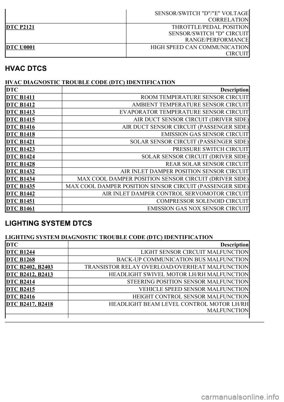
HVAC DIAGNOSTIC TROUBLE CODE (DTC) IDENTIFICATION
LIGHTING SYSTEM DIAGNOSTIC TROUBLE CODE (DTC) IDENTIFICATION
SENSOR/SWITCH "D"/"E" VOLTAGE
CORRELATION
DTC P2121 THROTTLE/PEDAL POSITION
SENSOR/SWITCH "D" CIRCUIT
RANGE/PERFORMANCE
DTC U0001 HIGH SPEED CAN COMMUNICATION
CIRCUIT
DTCDescription
DTC B1411 ROOM TEMPERATURE SENSOR CIRCUIT
DTC B1412 AMBIENT TEMPERATURE SENSOR CIRCUIT
DTC B1413 EVAPORATOR TEMPERATURE SENSOR CIRCUIT
DTC B1415 AIR DUCT SENSOR CIRCUIT (DRIVER SIDE)
DTC B1416 AIR DUCT SENSOR CIRCUIT (PASSENGER SIDE)
DTC B1418 EMISSION GAS SENSOR CIRCUIT
DTC B1421 SOLAR SENSOR CIRCUIT (PASSENGER SIDE)
DTC B1423 PRESSURE SWITCH CIRCUIT
DTC B1424 SOLAR SENSOR CIRCUIT (DRIVER SIDE)
DTC B1428 REAR SOLAR SENSOR CIRCUIT
DTC B1432 AIR INLET DAMPER POSITION SENSOR CIRCUIT
DTC B1434 MAX COOL DAMPER POSITION SENSOR CIRCUIT (DRIVER SIDE)
DTC B1435 MAX COOL DAMPER POSITION SENSOR CIRCUIT (PASSENGER SIDE)
DTC B1442 AIR INLET DAMPER CONTROL SERVOMOTOR CIRCUIT
DTC B1451 COMPRESSOR SOLENOID CIRCUIT
DTC B1461 EMISSION GAS NOX SENSOR CIRCUIT
DTCDescription
DTC B1244 LIGHT SENSOR CIRCUIT MALFUNCTION
DTC B1268 BACK-UP COMMUNICATION BUS MALFUNCTION
DTC B2402, B2403 TRANSISTOR RELAY OVERLOAD/OVERHEAT MALFUNCTION
DTC B2412, B2413 HEADLIGHT SWIVEL MOTOR LH/RH MALFUNCTION
DTC B2414 STEERING POSITION SENSOR MALFUNCTION
DTC B2415 VEHICLE SPEED SENSOR MALFUNCTION
DTC B2416 HEIGHT CONTROL SENSOR MALFUNCTION
DTC B2417, B2418 HEADLIGHT BEAM LEVEL CONTROL MOTOR LH/RH
MALFUNCTION
Page 4211 of 4500

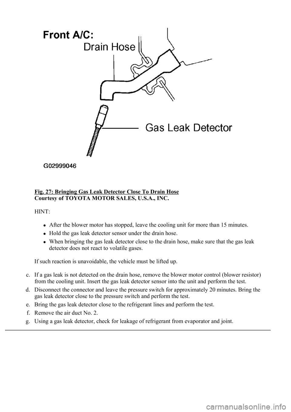
Fig. 27: Bringing Gas Leak Detector Close To Drain Hose
Courtesy of TOYOTA MOTOR SALES, U.S.A., INC.
HINT:
<0024004900570048005500030057004b004800030045004f0052005a004800550003005000520057005200550003004b0044005600030056005700520053005300480047000f0003004f004800440059004800030057004b00480003004600520052004f00
4c0051004a000300580051004c005700030049005200550003[more than 15 minutes.
Hold the gas leak detector sensor under the drain hose.
When bringing the gas leak detector close to the drain hose, make sure that the gas leak
detector does not react to volatile gases.
If such reaction is unavoidable, the vehicle must be lifted up.
c. If a gas leak is not detected on the drain hose, remove the blower motor control (blower resistor)
from the cooling unit. Insert the gas leak detector sensor into the unit and perform the test.
d. Disconnect the connector and leave the pressure switch for approximately 20 minutes. Bring the
gas leak detector close to the pressure switch and perform the test.
e. Bring the gas leak detector close to the refrigerant lines and perform the test.
f. Remove the air duct No. 2.
g.Using a gas leak detector, check for leakage of refrigerant from evaporator and joint.
Page 4212 of 4500
If there is leakage, check the tightening torque at the joints or evaporator.
Fig. 28: Checking For Leakage Of Refrigerant From Evaporator And Joint
Courtesy of TOYOTA MOTOR SALES, U.S.A., INC.
COMPONENTS
Page 4227 of 4500

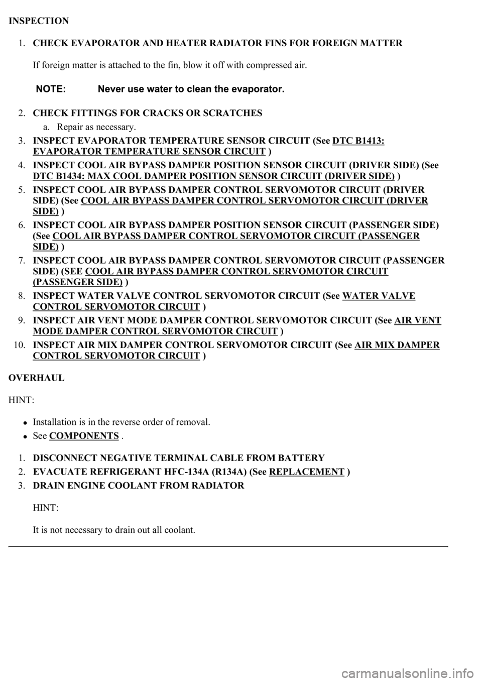
INSPECTION
1.CHECK EVAPORATOR AND HEATER RADIATOR FINS FOR FOREIGN MATTER
If foreign matter is attached to the fin, blow it off with compressed air.
2.CHECK FITTINGS FOR CRACKS OR SCRATCHES
a. Repair as necessary.
3.INSPECT EVAPORATOR TEMPERATURE SENSOR CIRCUIT (See DTC B1413:
EVAPORATOR TEMPERATURE SENSOR CIRCUIT )
4.INSPECT COOL AIR BYPASS DAMPER POSITION SENSOR CIRCUIT (DRIVER SIDE) (See
DTC B1434: MAX COOL DAMPER POSITION SENSOR CIRCUIT (DRIVER SIDE)
)
5.INSPECT COOL AIR BYPASS DAMPER CONTROL SERVOMOTOR CIRCUIT (DRIVER
SIDE) (See COOL AIR BYPASS DAMPER CONTROL SERVOMOTOR CIRCUIT (DRIVER
SIDE) )
6.INSPECT COOL AIR BYPASS DAMPER POSITION SENSOR CIRCUIT (PASSENGER SIDE)
(See COOL AIR BYPASS DAMPER CONTROL SERVOMOTOR CIRCUIT (PASSENGER
SIDE) )
7.INSPECT COOL AIR BYPASS DAMPER CONTROL SERVOMOTOR CIRCUIT (PASSENGER
SIDE) (SEE COOL AIR BYPASS DAMPER CONTROL SERVOMOTOR CIRCUIT
(PASSENGER SIDE) )
8.INSPECT WATER VALVE CONTROL SERVOMOTOR CIRCUIT (See WATER VALVE
CONTROL SERVOMOTOR CIRCUIT )
9.INSPECT AIR VENT MODE DAMPER CONTROL SERVOMOTOR CIRCUIT (See AIR VENT
MODE DAMPER CONTROL SERVOMOTOR CIRCUIT )
10.INSPECT AIR MIX DAMPER CONTROL SERVOMOTOR CIRCUIT (See AIR MIX DAMPER
CONTROL SERVOMOTOR CIRCUIT )
OVERHAUL
HINT:
Installation is in the reverse order of removal.
See COMPONENTS .
1.DISCONNECT NEGATIVE TERMINAL CABLE FROM BATTERY
2.EVACUATE REFRIGERANT HFC-134A (R134A) (See REPLACEMENT
)
3.DRAIN ENGINE COOLANT FROM RADIATOR
HINT:
It is not necessar
y to drain out all coolant.
Page 4237 of 4500
Fig. 51: Removing Hexagon Bolts (2 Of 2)
Courtesy of TOYOTA MOTOR SALES, U.S.A., INC.
19.REMOVE COOLER EVAPORATOR SUB-ASSY NO. 1
a. Remove the 6 screws and evaporator cover.
b. Pull out the evaporator.