2003 HONDA CIVIC Ignition switch
[x] Cancel search: Ignition switchPage 1084 of 1139
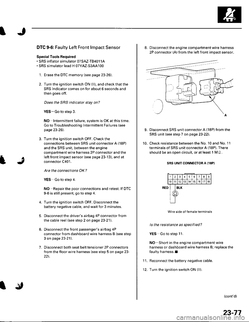
DTC 9-6: Faulty Left Front lmpact Sensor
Special Tools Required. SRS inflator simulator 07SAZ-TB4011A. SRS simulator lead H 07YM-S3AA100
1. Erase the DTC memory (see page 23-26).
2. Turn the ignition switch ON (ll), and check that the
SRS indicator comes on for about 6 seconds and
then goes off.
Does the SRS indicator stay on?
YES-Go to step 3.
NO Intermiftent failure, system is OK at this time.
Go to Troubleshooting Intermittent Failures (see
page 23-26).
3. Turn the ignition switch OFF. Check the
connections between SRS unit connector A (18P)
and the SRS unit. between the engine
compartment wire harness 2P connector and the
left front impact sensor {see page 23-13), and at
connector C401.
Are the connections OK?
YES Go to step 4.
NO-Repair the poor connections and retest. lf DTC
9-6 is still present, go to step 4.
Turn the ignition switch OFF. Disconnect the
battery negative cable. and wait for 3 minutes.
Disconnect the driver's airbag 4P connector from
the cable reel (see step 2 on page 23-21).
Disconnect the front passenger's airbag 4P
connector from dashboard wire harness B {see step
3 on page 23-21).
Disconnect both seat belt tensioner 2P connectors
from the floor wire harness (see step 5 on page 23-
22).
7.
9.
10.
8. Disconnect the engine compartment wire harness
2P connector {A) from the left front impact sensor.
Disconnect SRS unit connector A {18P) from the
SRS unit (see step 7 on page 23-22J.
Check resistance between the No. 10 and No. 11
terminals of SRS unit connector A (18P). There
should be an oDen circuit. or at least 1 M 0 .
SRS UNIT CONNECTOR A (18PI
Wire side of female terminals
ls the resistance as specitied?
YES Go to step 1 1.
NO-Short in the engine companment wire
harness or dashboard wire harness B; replace the
faulty harness.I
Reconnect the battery negative cable.
Turn the ignition switch ON { ll).
{cont'd}
RED
11.
12.
2356789
10tl1Zt315161718
I
T
ILK
23-77
Page 1085 of 1139
sRs
DTC Troubleshooting (cont'dl
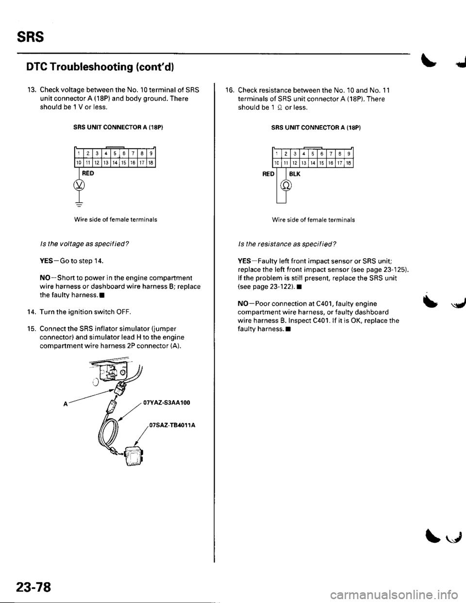
13. Check voltage between the No. 10 terminal of SRS
unit connector A (18P) and body ground. There
shouid be 'l V or less.
SRS UNIT CONNECTOR A {,I8P)
12378I
101112l3t4151611t6
RED
Wire side oI female terminals
ls the voltage as specitied?
YES-Go to step 14.
NO-Short to power in the engine compartment
wire harness or dashboard wire harness B; replace
the faulty harness.l
Turn the ignition switch OFF.
Connect the SRS inflator simulator (jumper
connector) and simulator lead H to the engine
compartment wire harness 2P connector (A).
07YAZ-S3AA100
07SAZ-TB,O11A
14.
t5.
23-78
\."r1
16. Check resistance between the No. 10 and No. 11
terminals of SRS unit connector A (18P). There
should be 1 0 or less.
SRS UNIT CONNECTOR A Il8PI
Wire side of female terminals
ls the rcsistance as specified?
YES Faulty left front impact sensor or SRS unit;
replace the left front impact sensor (see page 23-125).
lf the problem is still present, replace the SRS unit(see page 23-122).1
NO-Poor connection at C401, faulty engine
compartment wire harness, or faulty dashboard
wire harness B. Inspect C401. lf it is OK, replace the
faulty harness.l
= \y,
Page 1086 of 1139
)
t
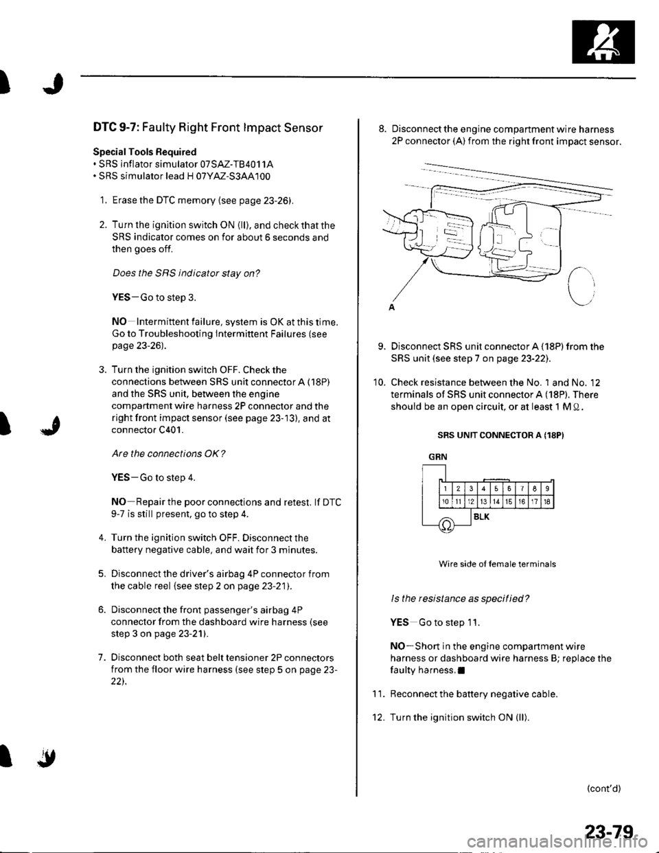
DTC 9-7: Faulty Right Front lmpact Sensor
Special Tools Bequired. SRS inflator simulator 07SAZ-TB4011A. SRS simulator lead H 07YM-S3AA100
1. Erase the DTC memory {see page 23-26).
2. Turn lhe ignition switch ON {ll), and checkthatthe
SRS indicator comes on for about 6 seconds and
then goes off.
Does the SRS indicator stay on?
YES-Go to step 3.
NO Intermittent failure, system is OK at this time.
Go to Troubleshooting Intermittent Failures (see
page 23-26).
3. Turn the ignition switch OFF. Check the
connections between SRS unit connectorA (18P)
and the SRS unit, between the engine
compartment wire harness 2P connector and the
right front impact sensor (see page 23-13), and at
connector C401.
Are the connections OK?
YES-Go to step 4.
NO Repair the poor connections and retest. lf DTC
9-7 is still present, go to step 4.
Turn the ignition switch OFF. Disconnect the
battery negative cable, and wait for 3 minutes.
Disconnect the driver's airbag 4P connector from
the cable reel {see step 2 on page 23-21).
Disconnect the front passenger's airbag 4P
connector from the dashboard wire harness (see
step 3 on page 23-21).
Disconnect both seat belt tensioner 2P connectors
from the floor wire harness (see step 5 on page 23-
22).
4.
5.
7.
I
'10.
Disconnect the engine compartment wire harness
2P connector (A) from the right front impact sensor.
Disconnect SRS unit connector A (18P) from the
SRS unit (see step 7 on page 23-221.
Check resistance between the No. 1 and No. 12
terminals of SRS unit connector A (18P). There
should be an open circuit, or at least 1 M 0.
SRS UNIT CONNECTOR A (18PI
GRN
11.
Wire side ol female terminals
ls the resistance as specified?
YES Go to step 11.
NO-Short in the engine companment wire
harness or dashboard wire harness B; replace the
faulty harness,I
Reconnect the battery negative cable.
Turn the ignition switch ON (ll).
(cont'd)
IF!-t1t2)l
Irolrlr
56I6
13161718
SLK
23-79
Page 1087 of 1139
sRs
DTC Troubleshooting (cont'd)
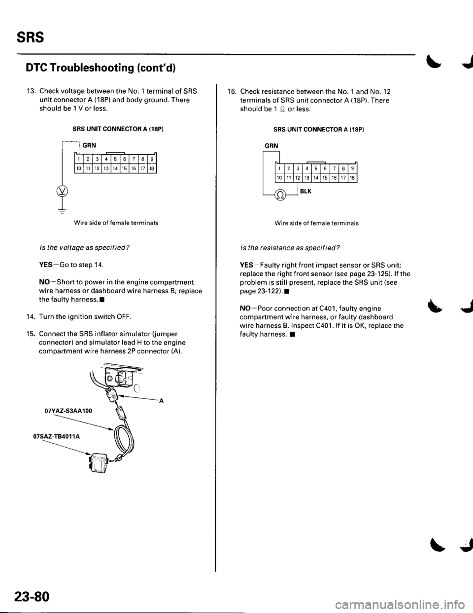
13. Check voltage between the No. 1terminal ofSRS
unit connector A (18P) and body ground. There
should be 1 V or less.
SRS UNIT CONNECTOR A I18P}
Wire side of female terminals
ls the voltage as specified?
YES Go to step 14.
NO-Short to power in the engine compartment
wire harness or dashboard wire harness B; replace
the faulty harness.l
Turn the ignition switch OFF.
Connect the SRS inflator simulator (jumper
connector) and simulator lead H to the engine
compartment wire harness 2P connector (A).
14.
07YAZ-S3AA100
23-80
16. Check resistance between the No. 1 and No. '12
terminals of SRS unit connector A (18P). There
should be 1 O or less.
SRS UNIT CONNECTOR A {18P)
GRN
Wire side of female terminals
ls the resistance as specitied?
YES Faulty right front impact sensor or SRS unit;
replace the rightfront sensor {see page 23-125). lfthe
problem is still present, replace the SRS unit (see
page 23-1221.a
NO- Poor connection at C401, faulty engine
compartment wire harness, or faulty dashboard
wire harness B. lnspect C401. lf it is OK, replace the
faulty harness, I
LJ
J_lr12lr
tE.]I
/A
56789
t311r51611t6
BLK
Page 1088 of 1139
I
)J
DTC 11-1: Open or Increased Resistance in
Driver's Side Airbag Inflator
SpecialTools Required. SRS inflator simulator 07SM-TB4011A. SRS simulator lead E 07XM-S140200
1. Erase the DTC memory (see page 23-26),
2. Tu rn the ignition switch ON (ll), and check that the
SRS indicator comes on for about 6 seconds and
then goes off.
Does the SBS indicatot stay on?
YES Go to step 3.
NO Intermittent failure, system is OK at this time.
Go to Troubleshooting Intermittent Failures (see
page 23-261.
3. Turn the ignition switch OFF. Disconnect the
battery negative cable, and wait for 3 minutes.
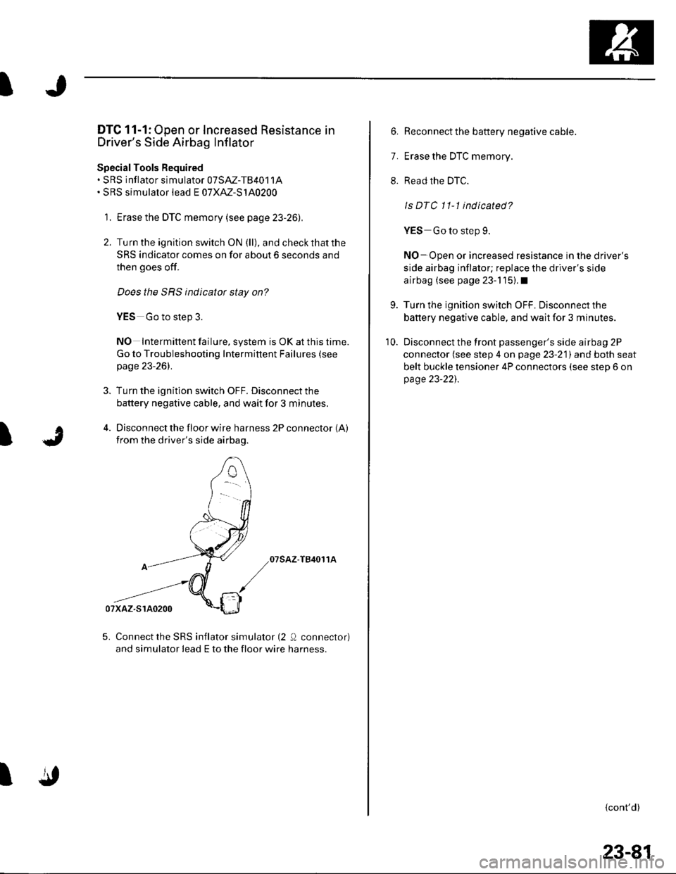
4. Disconnect the floor wire harness 2P connector (A)
from the driver's side airbag.
07sAz-T84011A
5. Connect the SRS inflator simulator (2 Q connector)
and simulator lead E to the floor wire harness.
I
6. Reconnect the battery negative cable.
7. Erase the DTC memory.
8. Read the DTC.
ls DTC 11-1 indicated?
YES Go to step 9.
NO-Open or increased resistance in the driver's
side airbag inflator; replace the driver's side
airbag (see page 23-1'15).1
9. Turn the ignition switch OFF. Disconnect the
battery negative cable, and wait for 3 minutes.
10. Disconnect the front passenger's side airbag 2P
connector (see step 4 on page 23-21) and both seat
belt buckle tensioner 4P connectors (see step 6 on
page 23-221.
{cont'd)
23-81
Page 1089 of 1139
sRs
'I t.
12
DTC Troubleshooting (cont'dl
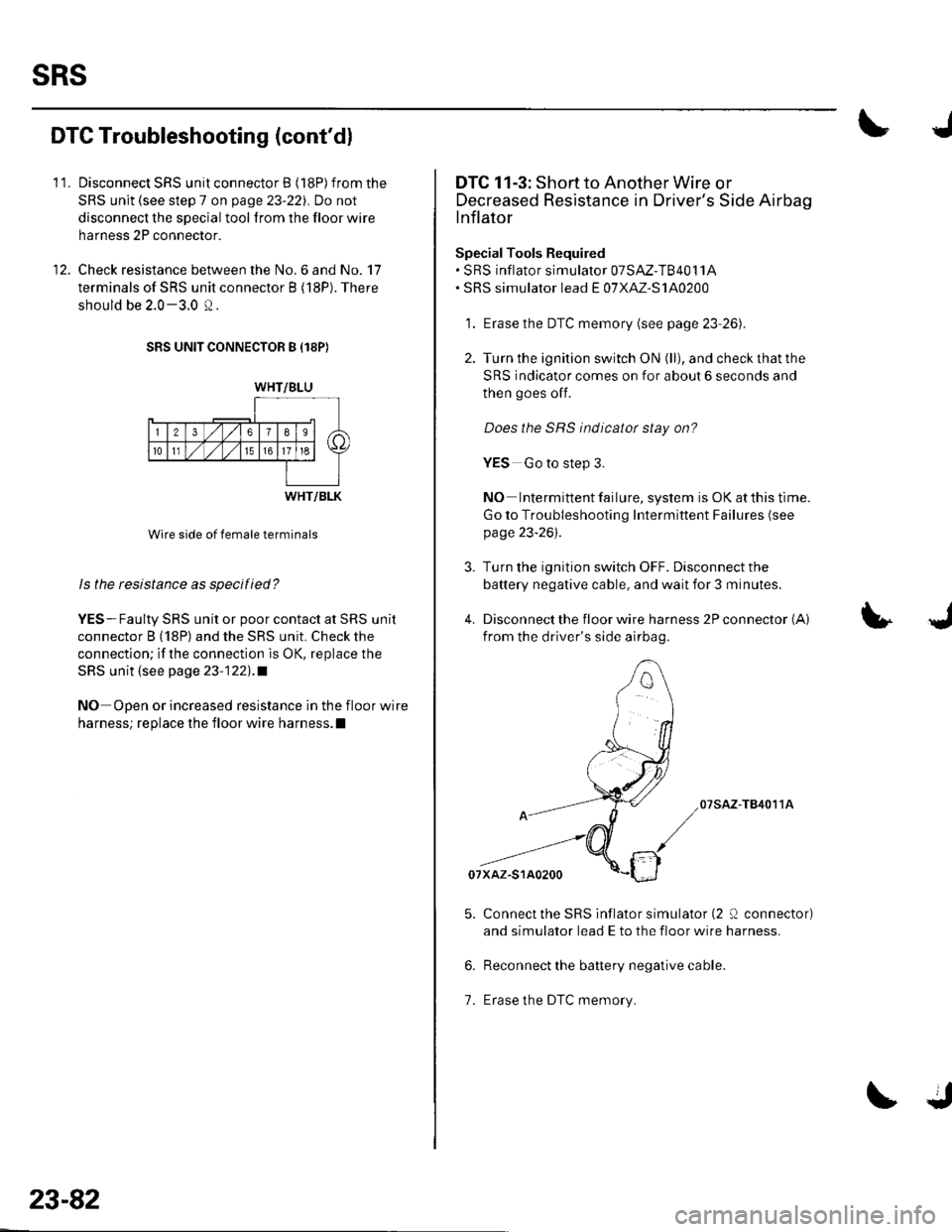
Disconnect SRS unit connector B (18P)from the
SRS unit (see step 7 on page 23-22). Do not
disconnect the special tool from the floor wire
harness 2P connector.
Check resistance between the No.6 and No. 17
terminals of SRS unit connector B (18P). There
should be 2.0 -3.0 Q.
SRS UNIT CONNECTOR B I18PI
WHT/BLU
rr--r-{lTlslsl a
IdFFI \
120
10tl15
WHT/BLK
Wire side of female terminals
ls the resistance as specified?
YES-Faulty SRS unit or poor contact at SRS unit
connector B (18P) and the SRS unit. Check the
connection; if the connection is OK, replace the
SRS unit (see page 23'1221.a
NO Open or increased resistance in the floor wire
harness; replace the floor wire harness.l
23-82
DTC 11-3: Short to Another Wire or
Decreased Resistance in Driver's Side Airbag
lnflator
SpecialTools Required' SRS inflator simulator 07SAZ-T84011A. SRS simulator lead E o7XAZ-S140200
1. Erase the DTC memory (see page 23 26).
2. Turn the ignition switch ON (ll), and check that the
SRS indicator comes on for about 6 seconds and
then goes off.
Does the SRS indicatot stay on?
YES Go to step 3.
NO Intermittent failure, system is OK at this time.
Go to Troubleshooting Intermittent Failures (see
page 23-26).
Turn the ignition switch OFF. Disconnect the
battery negative cable, and wait for 3 minutes.
Disconnect the floor wire harness 2P connector (A)
from the driver's side airbag.
07sAz-T84011A
Connect the SRS inflator simulator (2 0 connector)
and simulator lead E to the floor wire harness.
Reconnect the battery negative cable.
Erase the DTC memory.1.
Page 1090 of 1139
I
I
8. Read the DTC.
ls DTC 11-3 indicated?
YES-Go to step 9.
NO*Shon to another wire in the driver's side
airbag inflator; replace the driver's side airbag (see
page 23-115).I
9. Turn the ignition switch OFF. Disconnect the
battery negative cable. and wait for 3 minutes.
10. Disconnectthe front passenger's side airbag 2P
connector (see step 4 on page 23-21) and both seat
belt buckle tensioner 4P connectors (see step 6 on
page 23-22l,.
11. Disconnect the special tool from the floor wire
harness 2P connector.
12. Disconnect SRS unit connector B {18P)from the
SRS unit {see step 7 on page 23-221.
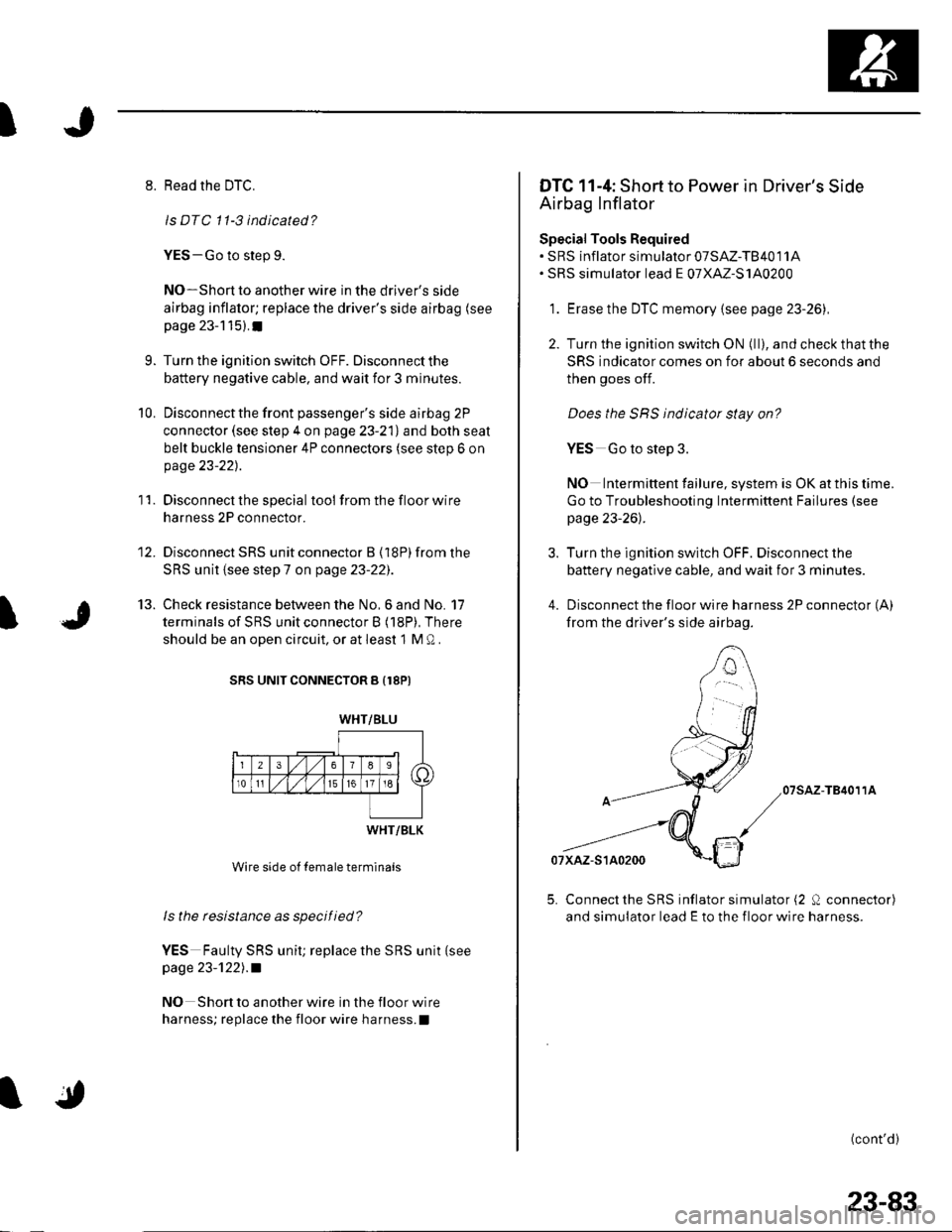
13. Check resistance between the No.6 and No. 17
terminals of SRS unit connector B (18P), There
should be an open circuit, or at least 1 M 0.
SRS UNIT CONNECTOR B {18PI
Wire side of female terminals
ls the resistance as specified?
YES Faulty SRS unit; replace the SRS unit {seepage 23-'t221 .a
NO Shon to another wire in the floor wire
harness; replace the floor wire ha rness.I
WHT/BLU
WHT/BLK
DTG 11-4: Short to Power in Driver's Side
Airbag Inflator
Special Tools Required. SRS inflator simulator 07SAZ-T84011A. SRS simulator lead E o7XAZ-S140200
1. Erase the DTC memory {see page 23-261.
2. Turn the ignition switch ON (ll), and check thatthe
SRS indicator comes on for about 6 seconds and
then goes off.
Does the SBS indicator stay on?
YES Go to step 3.
NO Intermittent failure, system is OK at this time.
Go to Troubleshooting Intermittent Failures (see
page 23-26l,.
3. Turn the ignition switch OFF. Disconnect the
battery negative cable, and wait for 3 minutes.
4. Disconnect the floor wire harness 2P connector (A)
from the driver's side airbag.
07sAz-TB4011A
5. Connect the SRS inflator simulator (2 0 connector)
and simulator lead E to the floor wire harness.
(cont'd)
23-83
Page 1091 of 1139
sRs
DTC Troubleshooting (cont'd)
6. Reconnect the battery negative cable.
7. Erase the DTC memory,
8. Read the DTC.
Is DTC 11-4 indicated?
YES-Go to step 9.
NO Short to power in the driver's side airbag
inflator; replace the driver's side airbag (see page
23-115).t
Turn the ignition swilch OFF. Disconnect the
battery negative cable, and wait for 3 minutes.
Disconnect the front passenger's side airbag 2P
connector (see step 4 on page 23-21) and both seat
belt buckle tensioner 4P connectors (see steD 6 on
page 23-221.
9.
'10.
23-84
\.J
11.Disconnect SRS unit connector B (18P) from the
SRS unit (see step 7 on page 23-22l,.
Turn the ignltion switch ON (ll).
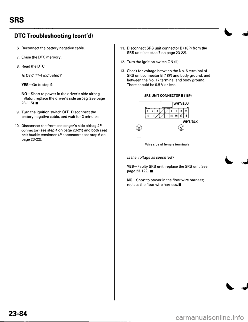
Check for voltage between the No. 6 terminal of
SRS unit connector B (18P) and body ground, and
between the No. 17 terminal and body ground.
There should be 0.5 V or less.
SRS UNIT CONNECTOR B I18P)
WHT/BLK
ls the voltage as specitied?
YES- Faulty SRS uniU replace the SRS unit (see
page 23-1221.a
NO Short to power in the floor wire harness;
replace the floor wire harness.l
't2.
13.
UJ