2003 HONDA CIVIC reset ecu
[x] Cancel search: reset ecuPage 44 of 1139

Starter Replacement
1. Make sure you have the anti-theft code for the radio.
then write down the frequencies for the radio's
preset buttons.
2. Disconnect the negative cable from the battery first,
then disconnect the positive cable.
3. Disconnect the knock sensor connector.
4. Remove the bolt (A) securing the harness bracket,
then remove the intake manifold bracket (B).
A6x1,0mm12 N.m {1.2 kgf.m,8.7 tbt.ft)
8 x 1.25 mm22 N,m 12.2 kgt.m,16 rbf.ftl
L't2.
4-9
5. Disconnect the starter cable (A)from the B terminal
on the solenoid, then disconnect the BLK,/WHT wire
{B) from the S terminal.
10 x 1.25 mm44 N.m {a.5 kgf.m,33lblft)
8 x 1.25 mm9Nm10.9 kgf.m,7 lbl ft)
7.
9.
'10.
11.
2
S'-12x12smm6ilNm{6.5 kgl m,47lbfft)
Remove the two bolts holding the starter, then
remove the starter.
lnstall the starter in the reverse order of removal.
Make sure the crimped side of the ring terminal (A)
is facing out.
Connect the positive cable and negative cable to
the batterY.
Start the engine to make sure the starter operates
propeny.
Enter the anti-theft code for the radio, then enter
the customer's radio station presets.
Set the clock.
Perform the engine control module (EcM) idle learn
procedure (see page 1 '1- 139 ).
I
Page 64 of 1139

l\-Alternator Replacement
1. Make sure you have the anti-theft code for the radio,
then write down the frequencies for the radio'spreset buttons,
2. Disconnect the negative cable from the battery first,
then disconnect the positive cable.
3. Remove the front bumper (see page 20-85).
4. Remove the right side headlight (see page 22-79).
5. Remove the reserve tank from the bracket.
6. Remove the drive belt (see page 4-26).
7. Remove the three bolts securing the alternator.
8 x 1.25 mm22 N.n 12.2 kgl.m,
Disconnect the alternator connector (A) and BLK
wire (B) from the alternator.
8 N.m10.8 kgf.m,6lbf.ft)
\
6
'I 1.
9.
10.
13.
14.
Remove the alternator.
Installthe alternator and drive belt in the reverse
order of removal.
Connect the positive cable and negative cable to
the battery.
Enter the anti-theft code for the radio, then enter
the customer's radio station presets.
Set the clock.
Perform the engine control module {ECM) idle learn
procedure (see page 11-139).
tt.
4-29
Page 82 of 1139

Engine Assembly
I
Engine Removal
Special Tools Required
Front subframe adapter EOS02C00001 1
NOTE:. Use fender covers to avoid damaging painted
surfaces.. To avoid damage, unplug the wiring connectors
carefully while holding the connector portion.. Mark all wiring and hoses to avoid misconnection.
Also, be sure that they do not contact other wiring orhoses, or interfere with other parts.
1. Secure the hood in the wide open position (support
rod in the lower hole).
2. Make sure you have the anti-theft code for the radio,
then write down the frequencies for the radio'spreset buttons.
3. Disconnect the negative cable from the battery first,then disconnect the positive cable.
4. Remove the battery.
5. Remove the intake manifold cover.
II
5-2
\,
6. Disconnectthe intake airtemperature (lAT) sensorconnector (A), remove the breather hose (B) and
vacuum hose (C), then remove the air cleaner
housing cover/intake air duct assemblv (D).
AC
7. Remove the air cleaner housing.
Page 211 of 1139

Fuel and Emissions Systems
General Troubleshooting Information (cont'dl
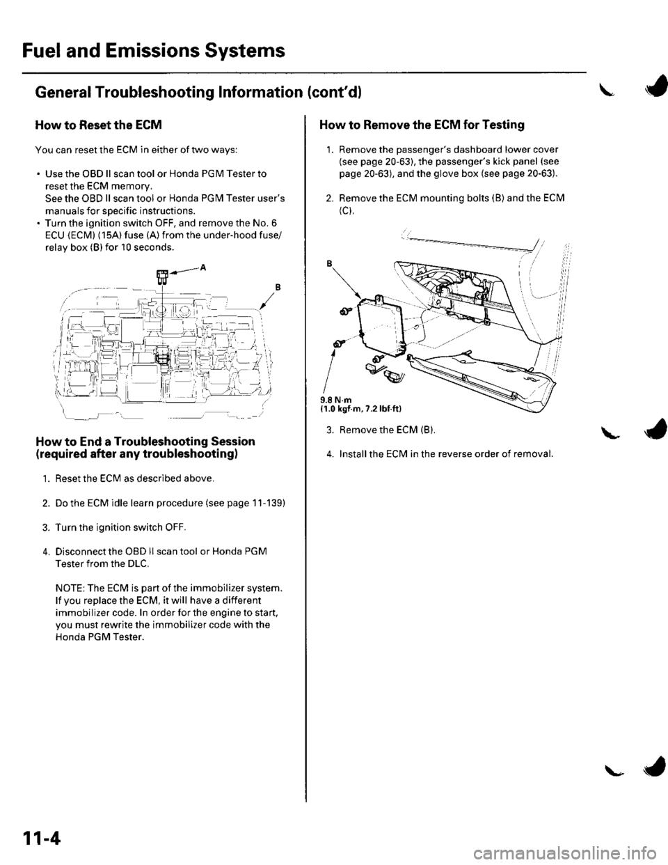
How to Reset the ECM
You can reset the ECM in either of two ways:
. Use the OBD ll scantool or Honda PGMTesterto
reset the ECM memory.
See the OBD ll scan tool or Honda PGI\4 Tester user's
manuals for specific instructions.' Turn the ignition switch OFF, and remove the No. 6
ECU {ECM} (15A) fuse (A)from the under-hood fuse/
relav box (Blfor 10 seconds.
How to End a Troubleshooting Session
(required after any troubleshootingl
1. Reset the ECM as described above.
2. Do the ECM idle learn procedure (see page 11-139)
3. Turn the ignition switch OFF.
4. Disconnectthe OBD ll scan tool or Honda PGM
Tester from the DLC.
NOTE: The ECM is part of the immobilizer system.
lf vou replace the ECM, it will have a different
immobilizer code. In order for the engine to start,
you must rewrite the immobilizer code with the
Honda PGM Tester.
11-4
\- ta
J
How to Remove the ECM for Testing
1. Remove the passenger's dashboard lower cover
{see page 20-63), the passenger's kick panel (see
page 20-63), and the glove box (see page 20-63).
2. Remove the ECM mounting bolts (B) and the ECM
(c),
9.8 N.m{1.0 kgf.m,7.2lbt.ft}
3. Remove the ECM (B).
4. Installthe ECM in the reverse order of removal.
L
Page 279 of 1139

PGM-FI System
IDTC Troubleshooting (cont'dl
DTC P0301: No. 1 Cylinder Misfire
DTC P0302: No. 2 Cylinder Misfire
DTC P0303: No. 3 Cylinder Misfire
DTC P0304: No. 4 Cylinder Misfire
1. After checking and recording the freeze data, reset
the ECM (see page 1 1-4). lf there is no freeze data of
the misfire, just clear the DTC.
2. Start the engine, and listen for a clicking sound
from the injector at the problem cylinder.
Does the injector click?
YES-Go to step 3.
NO-Go to step 30.
3. Turn the ignition switch OFF.
4. Exchange the ignition coil from the problem
cylinder with one from another cylinder,
5. Test-drive the vehicle for several minutes in the
range of the freeze data or under va rious
conditions if there was no freeze data.
6. Check for a DTC or a Temporary DTC with the scan
root.
ls DTC or Tempotaty DTC P0301, P0302, P0303
or P0304 ind icated?
YES Go to step 7.
NO Intermittent misfire due to poor contact at the
ignition coil connectors {no misfire at this time).
Make sure the coil connections are secure.l
11-72
8.
9.
1.
11.
Determine which cylinder(s) had the misfire.
Does the misf ire occur in the cylinder where the
ignition coil was exchanged?
YES Replace the faulty ignition coil.!
NO-Go to step 8.
Turn the ignition switch OFF.
Exchange the spark plug from the problem cylinder
with one from another cylinder.
Test-drive the vehicle for several minutes in the
range of the freeze data or under various
conditions if there was no freeze data.
Check for a DTC or Temporary DTC with the scan
Tool.
ls DTC ot Tempotary DTC P0301, P0302, P0303
or P0304 ind icated?
YES Go to step 12.
NO Intermittent misfire due to spark plug fouling,
etc. (no misfire at this time).1
Determine which cylinder(s) had the misfire.
Does the misl ire occur in the cylinder where the
spark plug was exchanged?
YES Replace the faulty spark plug.l
NO Go to step 13.
Turn the ignition switch OFF.
Exchange the lnjector from the problem cylinder
with one from another cylinder.
Let the engine idle for 2 minutes.
10.
14.
t5.
Page 288 of 1139

DTC P0563: ECM Power Source Circuit
U nexpected Voltage
1. Reset the ECI\4 {see page l1-4}.
2. Turn the ignition switch OFF.
3. Wait 5 seconds.
4. Turn the ignition switch ON {lll.
ls DTC P0563 indicated?
YES Go to step 5.
NO-lntermiltent failure, system is OK at this time.
Check for poor connections or loose terminals at
the No. 6 ECU (ECM) {15 A) fuse in the under-hood
fuse/relay box and at the ECM.I
Turn the ignition switch OFF.
Disconnect ECI\4 connector E {31P).
Turn the ignition switch ON (ll).
lvleasure voltage between ECM connector terminal
E7 and body ground.
6.
7.
8.
ECM CONNECTOR E {31P}
Wire side ol remale terminals
ls there battery voltage?
YES Go to step 12.
NO Go to step 9.
MRLY
9.
10.
Remove the glove box (see page 20-63).
Remove the PGM-FI main relay 1 (A7.
Check for continuity between ECM connector
terminal E7 and body ground.
ECM CONNECTOR E 131P)
MRLY{RED/YEL)
Wire side of {emale terminals
ls there continuity?
YES-Repair short in the wire between the ECM
{E7) and the PGM-Fl main relay 1 ,I
NO Replace the PGM-Fl main relay 1.1
Turn the ignition suitch OFF.
Reconnect ECM connector E (31P).
11.
tt.
'13.
(conl'd)
11-81
Page 346 of 1139

ECM ldle Learn Procedure
The idle learn procedure must be done so the ECM can
learn the engine idle characteristics.
Do the idle learn procedure whenever you do any of
these actions:. Disconnect the battery.
Replace the ECM or disconnect its connector.
Reset the ECM.
NOTE: Erasing DTCS with the Honda PGM Tester
does not require you to do the idle learn procedure.
Remove the No.6 ECU {ECM) ( 15A) fuse from the
under-hood fuse/relay box.
Remove the No.19 baftery (80A) fuse from the under-
hood fuse/relay box.
Remove PGM-FI main relay 1.
Remove any of the wires from the under-hood fuse/
retay Dox.
Disconnect any of the connectors from the under
hood fuse/relay box.
Disconnect the connector between the engine
compartment wire harness and ECM wire harness.
Disconnect the G2 terminal from the transmission
ho u srng.
Disconnectthe G'l terminal from the body.
Disconnectthe G101 terminal from the cylinder head
cover.
Procedure:
To complete the idle learn procedure, do this:
1. Make sure all electrical items (Ay'C, audio, rear
defogger, l:ghts, etc.,) are off.
2. Start the engine, and hold it at 3,000 rpm with no
load {in neutral) until the radiator fan comes on, or
until the engine coolanttemperature reaches 194"F(90'c).
3. Let the engine idle for about 5 minutes with the
throttle fully closed.
NOTE: lf the radiator fan comes on, do not include its
running time in the 5 minutes.
11-139
Page 502 of 1139

Steering
Steering Column Removal
lnstallation
1.
4.
Install the steering column, and make sure the
wires are not caught or pinched by any parts.
Insertthe upper end ofthe steering joint onto the
steering shaft {A) (line up the bolt hole (B) with the
flat portion (C) on the shaft).
8 x 1,25 mm28 N.m{2.9 kgf m,21 rbr.ft)
A
Slip the lower end of the steering joint onto the
pinion shaft {D) (line up the bolt hole with the
groove (E) around the shaft), and loosely lnstallthe
lower joint bolt. Be sure that the lower joint bolt is
securely in the groove in the pinion shaft.
Pull on the steering joint to make su re that the
steering joint is fully seated. Then installthe upper
joint bolt, and tighten it to the specified torque.
Tighten the lower joint bolt to the specified torque.
Finish the installation, and note these items:
. Make sure the wire harness is routed and
fastened properly.
. Make sure the connectors are properly connected.. Reinstallthe steering wheel (see page 17-8).
. Reconnect the battery.- Do the power window control unitreset
procedure {see page 22-128).- Enter the anti-theft code for the radio, then
enter the custmer's radio station presets.
- Set the clock.. Verify horn, turn signal switch, and cruise control
switch operation.. Check wheel alignment, if necessary (see page
18-4).. Do the engine control module (ECM) idle learn
procedu re {see page '11-139).
17-10
and Installation (cont'd){