2003 HONDA CIVIC Ignition switch
[x] Cancel search: Ignition switchPage 1109 of 1139
sRs
23.
24.
DTC Troubleshooting (cont'dl
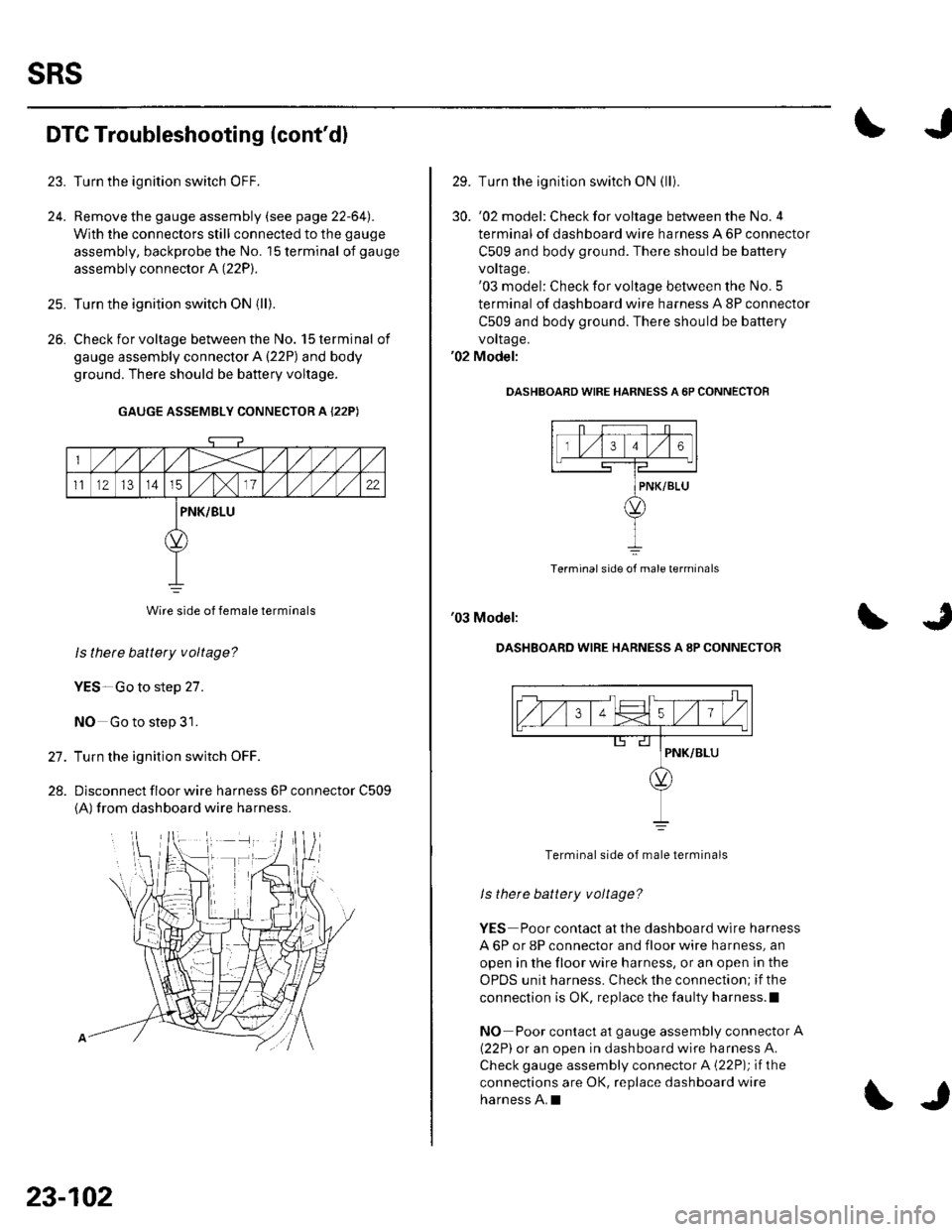
Turn the ignition switch OFF.
Remove the gauge assembly (see page 22-64l,.
With the connectors still connected to the gauge
assembly, backprobe the No. '15 terminal of gauge
assembly connector A (22P).
Turn the ignition switch ON {ll).
Check for voltage between the No. 15 terminal of
gauge assembly connector A {22P) and body
ground. There should be battery voltage.
GAUGE ASSEMBLY CONNECTOR A {22P)
Wire side of female terminals
ls thete battery voltage?
YES-Go to step 27.
NO Go to step 31.
Turn the ignition switch OFF.
Dlsconnect floor wire harness 6P connector C509
{A) from dashboard wire harness.
26.
27.
28.
23-102
\J
29. Turn the ignition switch ON (lli
30. '02 model: Checkforvoltage between the No.4
terminal of dashboard wire harness A 6P connector
C509 and body ground. There should be battery
vorlage.'03 model: Check for voltage between the No. 5
terminal of dashboard wire harness A 8P connector
C509 and body ground. There should be battery
vollage.'02 Model:
OASHBOARD WIRE HARNESS A 6P CONNECTOF
Terminal side of male terminals
'03 Model:
DASHBOARD WIRE HARNESS A 8P CONNECTOR
Terminal side of male terminals
ls there battety voltage?
YES Poor contact at the dashboard wire harness
A 6P or 8P connector and floor wire harness, an
open in the floor wire harness, or an open in the
OPDS unit harness. Check the connection; if the
connection is OK, replace the faulty harness.l
NO Poor contact at gauge assembly connector A
{22P) or an open in dashboard wire harness A.
Check gauge assembly connector A {22P); if the
connections are OK, replace dashboard wire
harness A.I
Page 1110 of 1139
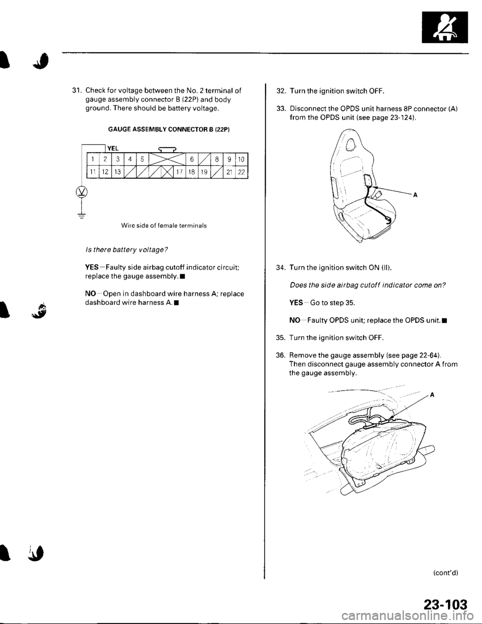
Check for voltage between the No. 2 terminal ofgauge assembly connector B (22P) and bodyground. There should be battery voltage.
GAUGE ASSEMBLY CONNECTOR B {22P)
Wire side of female terminals
ls there battery voltage?
YES Faulty side airbag cutoff indicator circuit;
replace the gauge assembly.l
NO Open in dashboard wire harness A; replace
dashboard wire harness A.I
YEL
12345X68910
1t12IJ,/1,/1,/)112122
\,
32.
33.
35.
36.
34.
Turn the ignition switch OFF.
Disconnect the OPDS unit harness 8P connector (A)
from the OPDS unit (see page 23- 124).
Turn the ignition switch ON (ll).
Does the slde airbag cutotf indicator come on?
YES Go to step 35.
NO Faulty OPDS unit; replace the OPDS unit.l
Turn the ignition switch OFF.
Remove the gauge assembly (see page 22-64).
Then disconnect gauge assembly connector A from
the gauge assembly.
(cont'd)
23-103
Page 1111 of 1139
sRs
DTG Troubleshooting (cont'dl
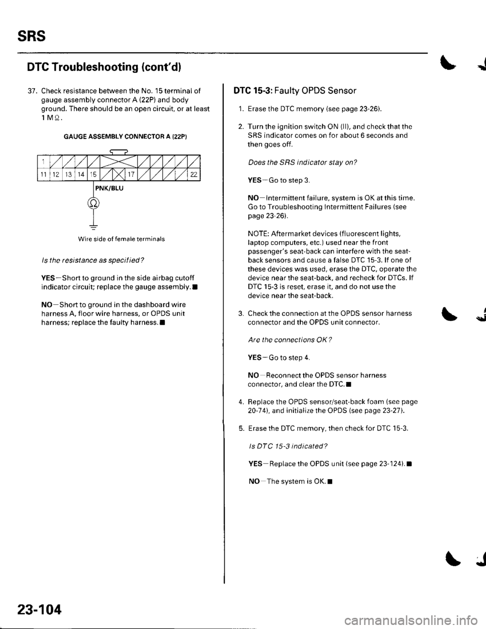
37. Check resistance between the No. 15 terminal of
gauge assembly connector A (22P) and body
ground. There should be an open circuit, or at least
1M0.
GAUGE ASSEMBLY CONNECTOR A I22PI
ls the resistance as specified?
YES-Short to ground in the side airbag cutoff
indicator circuit; replace the gauge assembly.l
NO Short to ground in the dashboard wire
harness A, floor wire harness, or OPDS unit
harness; replace the faulty harness.l
Wire side of female terminals
23-104
J
DTC 15-3: Faulty OPDS Sensor
1. Erase the DTC memory {see page 23-261.
2. Turn the ignition switch ON (ll), and check that the
SRS indicator comes on for about 6 seconds and
then goes off.
Does the SRS indicator stay on?
YES-Go to step 3.
NO Intermittent failure, system is OK at this time.
Go to Troubleshooting Intermittent Failures (see
page 23-26).
NOTE: Aftermarket devices (fluorescent lights,
laptop computers, etc.) used near the front
passenger's seat-back can interfere with the seat-
back sensors and cause a false DTC 15-3. lf one of
these devices was used, erase the DTC, operate the
device near the seat-back, and recheck for DTCs. lf
DTC 15-3 is reset, erase it, and do not use the
device near the seat-back.
3.
4.
Check the connection at the OPDS sensor harness
connector and the OPDS unit connector.
Are the connections OK?
YES-Go to step 4.
NO Reconnect the OPDS sensor harness
connector, and clear the DTC.I
Replace the OPDS sensor/seat-back foam (see page
20-141, and initialize the OPDS (see page 23-27).
Erase the DTC memory, then check for DTC 15-3.
ls DTC 15-3 indicated?
YES Replace the OPDS unit (see page 23-1241.a
NO The system is OK.l
{
Page 1112 of 1139
I
d
\9I
SRS Indicator Circuit Troubleshooting
The SRS Indicator Doesn't Come On
1. Turn the ignition switch ON (ll), and see if the otherindicators come on {brake system, etc).
Do the other indicators come on?
YES Go to step 2.
NO-Go to step 8.
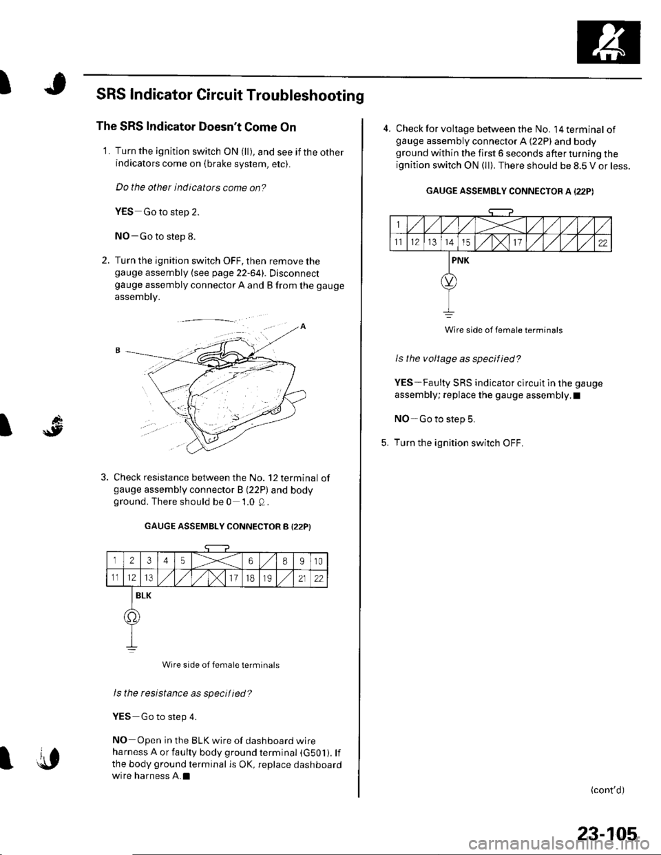
2. Turn the ignition switch OFF, then remove thegauge assembly {see page 22-641. Disconnectgauge assembly connector A and B from the gauge
assembly.
Check resistance between the No. 12 terminal ofgauge assembly connector B (22P) and bodyground. There should be 0 1.0 Q.
GAUGE ASSEMBLY CONNECTOR B I22PI
12345X68910
1112l3/)x111B2122
BLK
o.
Wire side of female terminals
Is the resistance as specified?
YES Go to step 4.
NO Open in the BLK wire of dashboard wire
harness A or faulty body ground terminal (G501). lf
the body ground terminal is OK, replace dashboard
wire harness A.Il{,
23-105
4. Check for voltage between the No. l4terminal ofgauge assembly connector A (22P) and bodyground within the first 6 seconds after turning the
ignition switch ON (ll). There should be 8.5 V or less.
GAUGE ASSEMBLY CONNECTOR A I22PI
Wire side of female terminats
Is the voltage as specified?
YES-Faulty SRS indicator clrcuit in the gauge
assembly; replace the gauge assembly.I
NO-Go to step 5.
Turn the ignition switch OFF.
(cont'd)
Page 1113 of 1139
sRs
6.
SRS Indicator Circuit Troubleshooting (cont'dl
7.
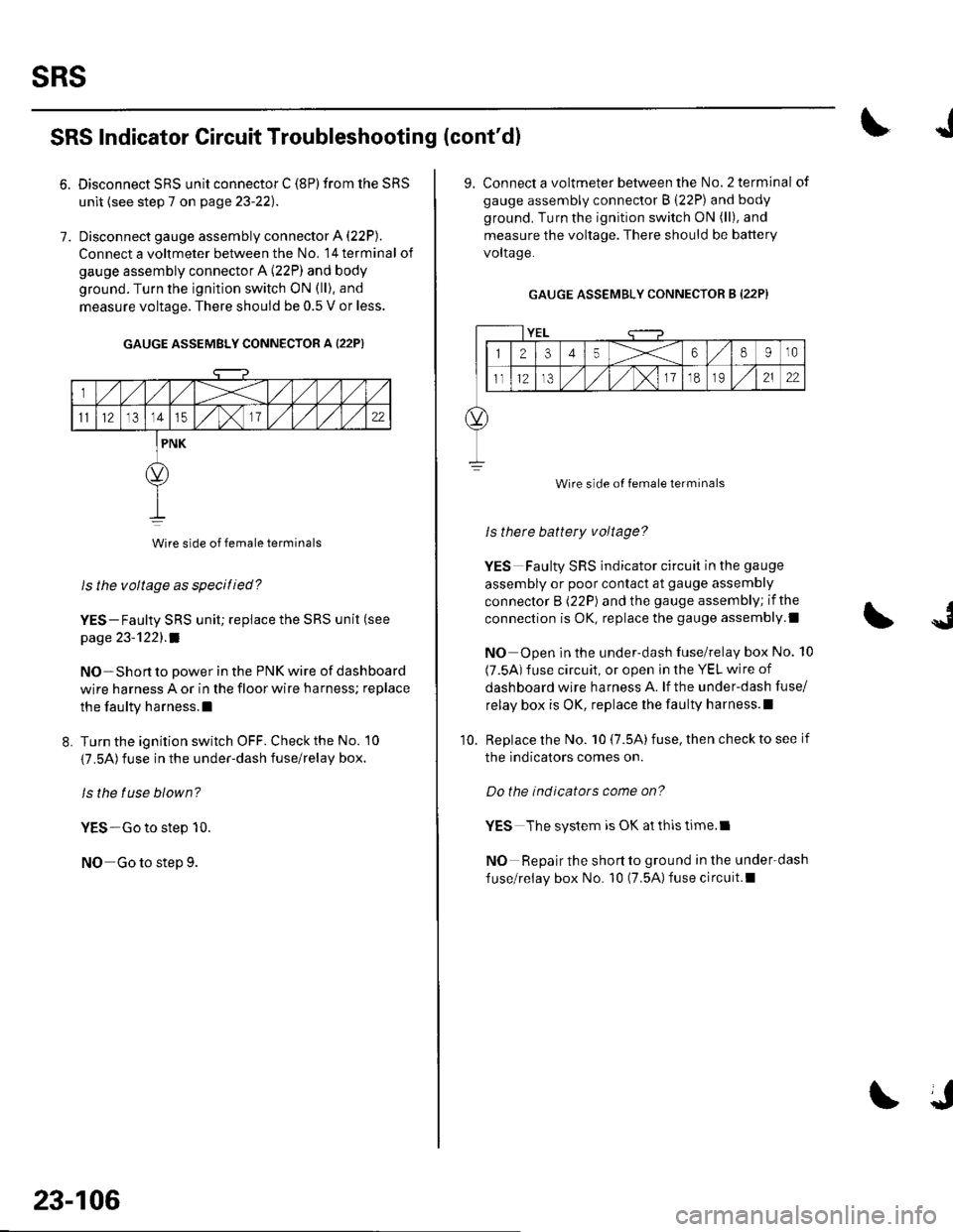
Disconnect SRS unit connector C (8P) from the SRS
unit {see step 7 on page 23-22).
Disconnect gauge assembly connector A (22P).
Connect a voltmeter between the No, l4terminal of
gauge assembly connector A (22P) and body
ground. Turn the ignition switch ON (ll), and
measure voltage. There should be 0.5 V or less.
GAUGE ASSEMBLY CONNECTOR A {22P)
Wire side of female terminals
ls the voltage as specitied?
YES-Faulty SRS unit; replace the SRS unit (see
page 23-'l22l.a
NO-Short to power in the PNK wire of dashboard
wire harness A or in the floor wire harness; replace
the faulty harness.l
L Turn the ignition switch OFF. Check the No. 10
{7.5A)fuse in the under-dash fuse/relay box.
ls the tuse blown?
YES-Go to step 10.
NO Go to step 9.
23-106
J
9. Connect a voltmeter between the No.2 terminal of
gauge assembly connector B (22P) and body
ground. Turn the ignition switch ON (ll), and
measure the voltage. There should be battery
voltaqe.
GAUGE ASSEMBLY CONNECTOR B (22P}
YEL
12345X68910
ll12,/ ,/,/x11o2122
Wire side of female terminals
ls therc battery voltage?
YES Faulty SRS indicator circuit in the gauge
assembly or poor contact at gauge assembly
connector B (22P) and the gauge assembly; if the
connection is OK, replace the gauge assembly.l
NO Open in the under-dash fuse/relay box No. 10
(7.5A) fuse circuit, or open in the YEL wire of
dashboard wire harness A. lf the under-dash fuse/
relay box is OK, replace lhe faulty harness.l
Replace the No. 10 (7.5A) fuse, then check to see if
the indicators comes on.
Do the indicators come on?
YES The system is OK at thls time.l
NO Repair the short to ground in the under-dash
fuse/relay box No. 10 (7.5A)fuse circuit.l
10.
Page 1114 of 1139
JI
I
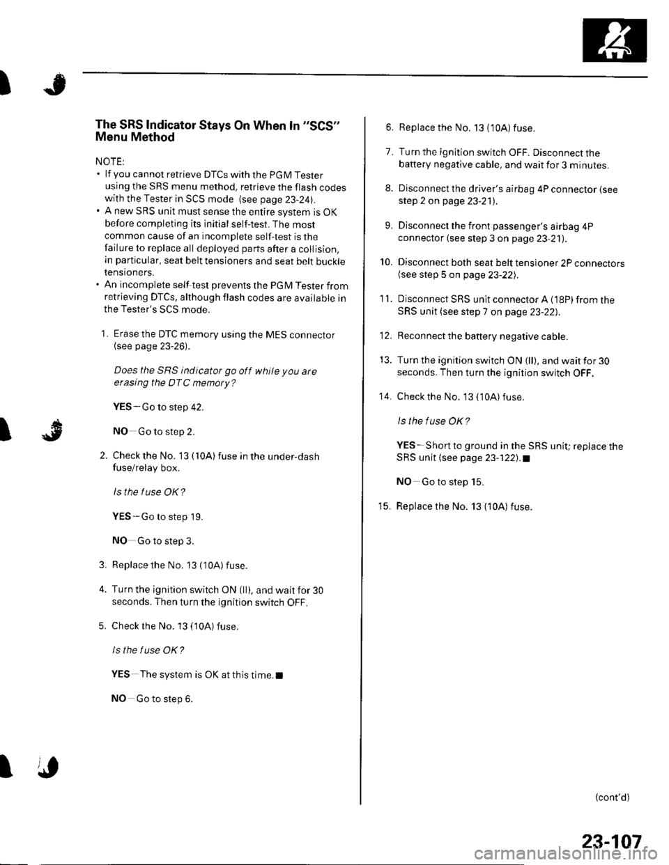
The SRS lndicator Stays On When ln "SCS"
Menu Method
NOTE:. lf you cannot retrieve DTCSwith the PGM Tester
using the SRS menu method. retrieve the flash codeswith the Tester in SCS mode {see page 23-24|,.. A new SRS unit must sense the entire system is OK
before completing its initial self-test. The most
common cause of an incomplete self-test is the
failure to replace all deployed parts after a collision,
in particular, seat belt tensioners and seat belt buckletenstoners.. An incomplete self-test prevents the PGM Tester fromretrieving DTCS, although flash codes are available in
the Tester's SCS mode.
1 . Erase the DTC memory using the MES connector(see page 23-26).
Does the SRS indicator go off while you are
erasing the DTC memory?
YES-Go to step 42.
NO Go to step 2.
Check the No. '13 { 10A) fuse in the under-dash
fuse/relay box.
lsthe f use OK?
YES--Go to step 19.
NO Go to step 3.
Replacethe No. 13 (10A) fuse.
Turn the ignition switch ON (ll), and wait for 30
seconds. Then turn the ignition switch OFF.
Check rhe No. 13 (10A) fuse.
ls the f use OK?
YES The system is OK at this time.I
NO Go to step 6.
3.
I
6. Replace the No. 13 (10A) fuse.
7. Turn the ignition switch OFF. Disconnect the
battery negative cable, and wait for 3 minutes.
8. Disconnect the driver's airbag 4P connector (see
step 2 on page 23-21).
9. Disconnect the front passenger's airbag 4P
connector (see step 3 on page 23,21).
10. Disconnect both seat belt tensioner 2P connectors(see step 5 on page 23-221.
'11. DisconnectSRS unitconnectorA{18P)fromthe
SRS unit (see step 7 on page 23-22],.
'12. Reconnect the battery negative cable.
13. Turn the ignition switch ON (ll), and wait for 30
seconds. Then turn the ignition switch OFF.
14. Checkthe No. 13 ('10A) fuse.
ls the f use OK?
YES-Short to ground in the SRS unit; replace the
SRS unit (see page 23-122).a
NO Go to step 15.
15. Replace the No. 13 (10A) fuse.
{cont'd)
23-107
Page 1115 of 1139
sRs
from the under-dash fuse/relav bor.
11.
18.
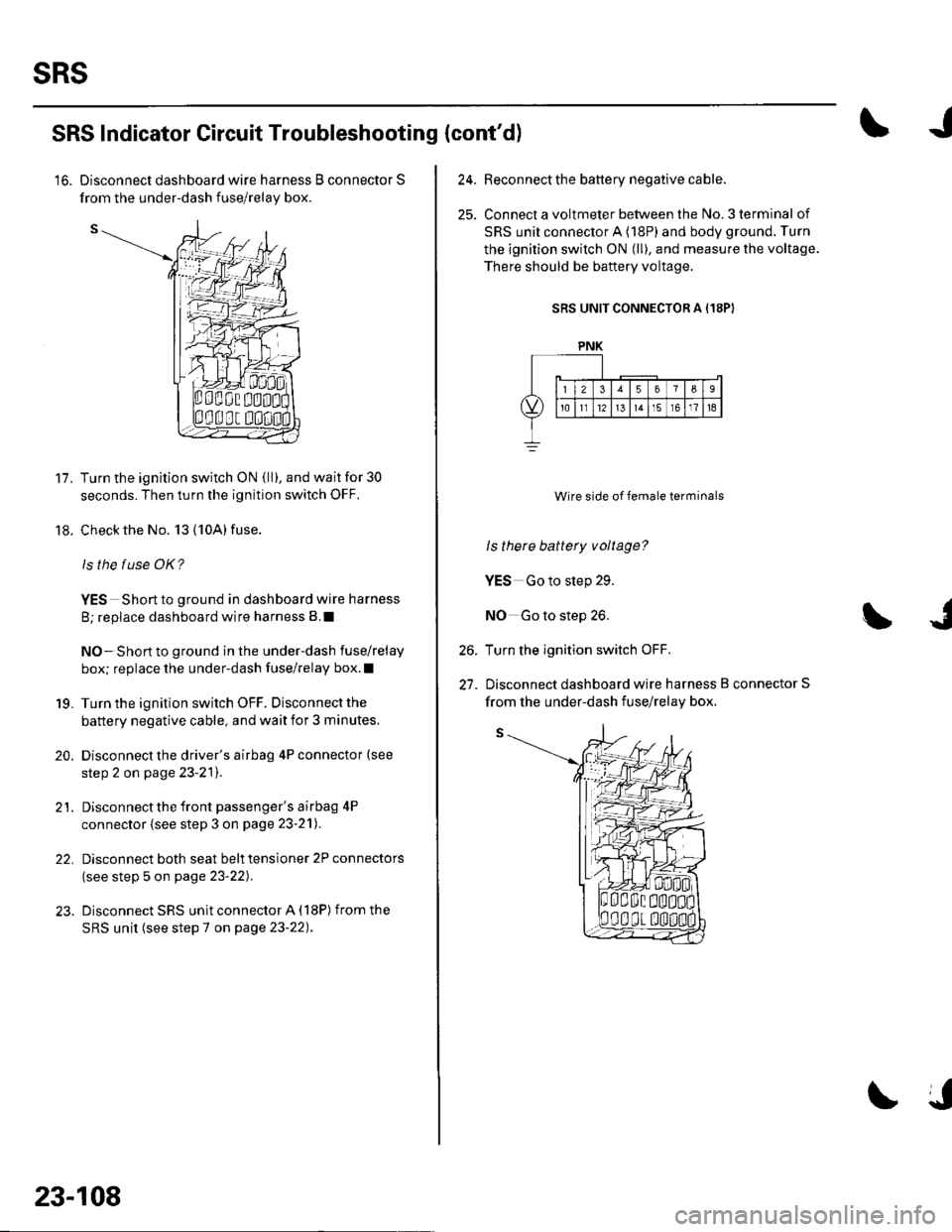
SRS Indicator Circuit Troubleshooting (cont'd)
'16. Disconnect dashboard wire harness B connector S
Turn the ignition switch ON {ll), and wait for 30
seconds. Then turn the ignition switch OFF,
Check the No. 13 (10A) fuse.
ls the f use OK?
YES Short to ground in dashboard wire harness
B; replace dashboard wire harness B.I
NO-Short to ground in the under-dash fuse/relay
box; replace the under-dash fuse/relay box.l
Turn the ignition switch OFF. Disconnect the
battery negative cable, and wait for 3 minutes.
Disconnect the driver's airbag 4P connector (see
step 2 on page 23-2'l).
Disconnect the front passenger's airbag 4P
connector (see step 3 on page 23-21).
Disconnect both seat belt tensioner 2P connectors
(see step 5 on page 23-22).
Disconnect SRS unit connector A (18P) from the
SRS unit (see step 7 on page 23-22).
19.
20.
21.
22.
23-108
24.Beconnect the battery negative cable.
Connect a voltmeter between the No. 3 terminal of
SRS unit connector A (18P) and body ground. Turn
the ignition switch ON (ll), and measure the voltage.
There should be baftery voltage.
SRS UNIT CONNECTOR A (18PI
Wire side of female terminals
ls there battery voltage?
YES Go to step 29.
NO Go to step 26.
Turn the ignition switch OFF.
Disconnect dashboard wire harness B connector S
26.
27.
PNK
from the under-dash fuse/relav box.
Page 1116 of 1139
I
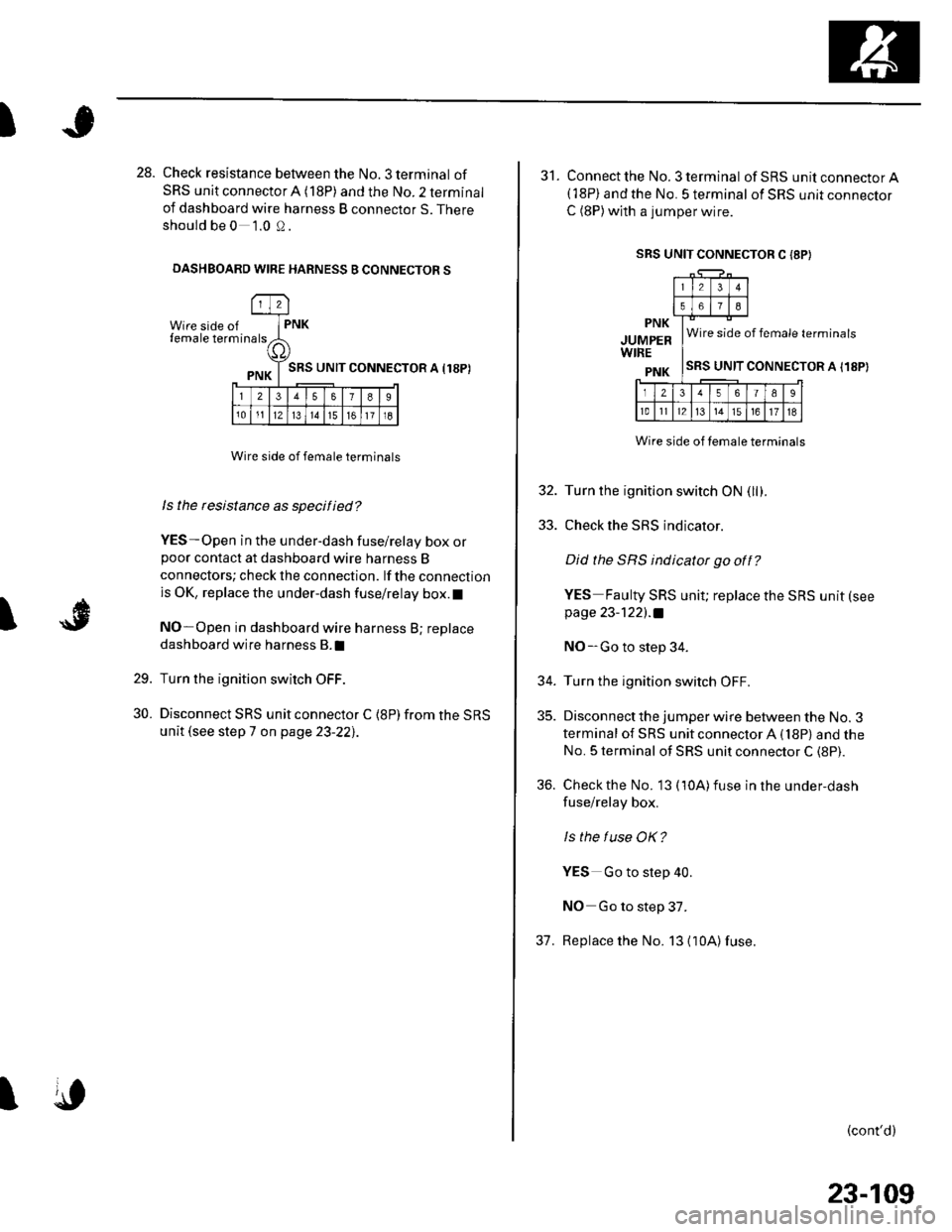
28. Check resistance between the No. 3 terminal of
SRS unit connector A (18P) and the No. 2 terminal
of dashboard wire harness B connector S. There
should be 0 1.0 0.
DASHBOARD WIRE HARNESS B CONNECTOR S
Wire side offemale term
l2
rna lsPNK
a,
PNK T SRS uNrr
l23578I
101112l314151611l8
CONNECTOR A I18P)
I
Wire side of female terminals
ls the rcsistance as specified?
YES-Open in the under-dash fuse/relay box orpoor contact at dashboard wire harness B
connectors; check the connection. lf the connection
is OK, replace the under-dash fuse/relay box.l
NO-Open in dashboard wire harness B; replace
dashboard wire harness B.I
Turn the ignition switch OFF.
Disconnect SRS unit connector C {8P) from the SRS
unit (see step 7 on page 23-22],.
29.
30.
I
SRS UNIT CONNECTOR C I8P}
31. Connect the No. 3 terminal ofSRS unitconnectorA(18P) and the No. 5 terminal of SRS unit connector
C (8P)with a jumper wire.
PNK
JUMPERWIRE
PNK
Wire side of female terminals
SRS UNIT CONNECTOR A I18P)
Wire side of temale terminals
32. Turn the ignition switch ON (llf .
33. Check the SRS indicator.
Did the SRS indicator go off?
YES Faulty SRS unit; replace the SRS unit (see
page 23-122l.a
NO-Go to step 34.
34. Turn the ignition switch OFF.
35. Disconnect the jumper wire between the No. 3
terminal of SRS unit connector A (18P) and the
No. 5 terminal of SRS unit connector C (8P).
36. Check the No. 13 (10A)fuse in the under,dash
fuse/relay box.
ls the f use OK?
YES Go to step 40.
NO Go to step 37.
37. Replace the No. 13 {10A)fuse.
(cont'd)
23-109