Page 3024 of 4378
GENERAL PROCEDURES
Switch Adjustment —
Deactivator
1. Adjust the deactivator switch. 1. Disconnect the switch hook from the brake pedal.
2. Depress the switch hook and plunger into the deactivator switch body until the adjustment locking tab snaps into place within the hook.
3. Depress the brake pedal and reattach the switch hook.
SECTION 310-
03: Speed Control 2003 Mustang Workshop Manual �K�l�j . 1 �b�a
12003 Mustang Workshop Manual
18. 11. 2011file:///C:/Ford/2000 - 2004/tsocache/SHEF_2308/S3B~us~en~ ...
Page 3091 of 4378

GENERAL PROCEDURES
Air Conditioning (A/C) System Check —
Retail Procedure
NOTE: This Retail Procedure is not eligible for claiming on Ford paid repairs (warranty and ESP).
NOTE: The engine should be run at idle for 10 minutes with the air conditioning on and set to MAX A/C
before carrying out this retail procedure.
NOTE: Read and follow all of the Warnings, Cautions and Notes at the beginning of this section before
continuing.
1. Visual inspection
Open the hood and visually inspect the heating and air conditioning systems for the following:
�zCoolant reservoir for correct coolant level
�z Heater hoses for deterioration or loose connections
�z Radiator and condenser for debris or damaged fins restricting airflow, loose mounting or
connections
�z Accessory drive belt(s) and cooling fan(s) for wear or physical damage
�z Refrigerant lines and connections for physical damage or loose connections
�z Compressor for physical damage or loose connections
�z Suction accumulator/drier for physical damage or loose connections
�z Wiring and connectors for excessive wear, loose or damaged connections, or incorrect
routing
2. A/C refrigerant analysis
�zCarry out air conditioning refrigerant analysis. For additional information, refer to
Refrigerant Identification Testing in this section.
�z If the refrigerant fails the analysis, discontinue diagnosis and make recommendations for
repairs.
�z If the refrigerant passes the analysis, carry out the air conditioning system check.
3. Air conditioning system check
�zConnect manifold gauge set or charging station with gauges to refrigerant system.
�z With the vehicle in park, parking brake set, thermometer installed in center panel vent,
and air conditioning system on and set to MAX A/C, start the engine.
�z Record air refrigerant system pressures while running the engine at 1,500 rpm and allow
engine to return to idle.
�z Operate the blower motor in all control positions and check for correct blower speed
changes.
�z With the blower motor on HI, operate air discharge mode selector in all positions and
check for correct airflow in each position.
�z Operate the temperature blend selector in all positions and check for correct change in
discharge temperature. Check the air discharge temperature with the selector in the
coolest position and the air conditioning on and set to MAX A/C to determine if the air
discharge temperature is acceptable for the current ambient air temperature.
�z Carry out the EATC self- test (if applicable).
If the refrigerant system pressures were low, carry out the refrigerant system leak test.
SECTION 412-
00: Climate Control System - General Information 2003 Mustang Workshop Manual �K�l�j . 1 �b�a
22003 Mustang Workshop Manual
18. 11. 2011file:///C:/Ford/2000 - 2004/tsocache/SHEF_2308/S3B~us~en~ ...
Page 3113 of 4378

GENERAL PROCEDURES
Electronic Leak Detection
CAUTION: Good ventilation is necessary in the area where electronic A/C leak testing is to
be carried out. If the surrounding air is contaminated with refrigerant gas, the leak detector will
indicate this gas all the time. Odors from other chemicals such as anti- freeze, diesel fuel, disc
brake cleaner, or other cleaning solvents can cause the same problem. A fan, even in a well-
ventilated area, is very helpful in removing small traces of contamination from the air that
might affect the leak detector.
1. NOTE: The system pressure should be between 413- 551 kPa (60-80 psi) at 24°C (75°F) with
the engine off.
Leak test the refrigerant system using the Refrigerant Leak Detector. Follow the instructions
included with the leak detector for handling and operation techniques.
2. If a leak is found, discharge and recover the refrigerant. For additional information, refer to Air Conditioning (A/C) System Recovery, Evacuation and Charging in this section.
�z Repair the system.
�z Test the system for normal operation.
SECTION 412-
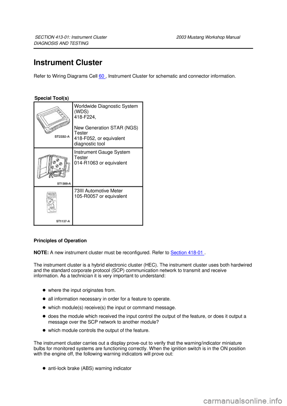
00: Climate Control System - General Information 2003 Mustang Workshop Manual Special Tool(s)
H10PM Refrigerant Leak
Detector With Battery
216-
00001 or equivalent �K�l�j . 1 �b�a
22003 Mustang Workshop Manual
18. 11. 2011file:///C:/Ford/2000 - 2004/tsocache/SHEF_2308/S3B~us~en~ ...
Page 3259 of 4378
DESCRIPTION AND OPERATION
Instrument Cluster
The instrument cluster (10849) consists of the following components:
Instrument Cluster—
Base 3.8L Engine
SECTION 413-
01: Instrument Cluster 2003 Mustang Workshop Manual Item Part
Number Description
1 — Fuel gauge
2 — Engine coolant temperature gauge
3 — Speedometer
4 — Turn signal/hazard indicator
5 — High beam indicator
6 — Tachometer
7 — Odometer
8 — Trip odometer reset button
9 — Voltmeter gauge
10 — Oil pressure gauge
11 — CHECK FUEL CAP indicator
12 — BRAKE warning indicator
13 — ABS warning indicator
14 — Traction control indicator
15 — Overdrive off (O/D OFF) indicator (automatic �K�l�j . 1 �b�a
42003 Mustang Workshop Manual
18. 11. 2011file:///C:/Ford/2000 - 2004/tsocache/SHEF_5108/S3B~us~en~ ...
Page 3260 of 4378
Instrument Cluster—
Base 4.6L Engine transmission)
16 — LOW FUEL level indicator
17 — SERVICE ENGINE SOON indicator
18 — THEFT indicator
19 — AIR BAG warning indicator
20 — Charging system indicator
21 — Safety belt warning indicator
Item Part
Number Description
1 — Fuel gauge
2 — Engine coolant temperature gauge
3 — Speedometer
4 — Turn signal/hazard indicator
5 — High beam indicator
6 — Tachometer
7 — Odometer
8 — Trip odometer reset button
9 — Voltmeter gauge
10 — Oil pressure gauge
11 — CHECK FUEL CAP indicator
12 — BRAKE warning indicator
13 — ABS warning indicator �K�l�j . 2 �b�a
42003 Mustang Workshop Manual
18. 11. 2011file:///C:/Ford/2000 - 2004/tsocache/SHEF_5108/S3B~us~en~ ...
Page 3261 of 4378
Instrument Cluster—
Cobra 14 — Traction control indicator
15 — Overdrive off (O/D OFF) indicator (automatic
transmission)
16 — LOW FUEL level indicator
17 — SERVICE ENGINE SOON indicator
18 — THEFT indicator
19 — AIR BAG warning indicator
20 — Charging system indicator
21 — Safety belt warning indicator
Item Part
Number Description
1 — Fuel gauge
2 — Engine coolant temperature gauge
3 — Speedometer
4 — Turn signal/hazard indicator
5 — High beam indicator
6 — Tachometer
7 — Odometer
8 — Trip odometer reset button
9 — Boost gauge
10 — Oil pressure gauge
11 — CHECK FUEL CAP indicator
12 — BRAKE warning indicator �K�l�j . 3 �b�a
42003 Mustang Workshop Manual
18. 11. 2011file:///C:/Ford/2000 - 2004/tsocache/SHEF_5108/S3B~us~en~ ...
Page 3263 of 4378

DIAGNOSIS AND TESTING
Instrument Cluster
Refer to Wiring Diagrams Cell
60 , Instrument Cluster for schematic and connector information.
Principles of Operation
NOTE: A new instrument cluster must be reconfigured. Refer to Section 418 - 01 .
The instrument cluster is a hybrid electronic cluster (HEC). The instrument cluster uses both hardwired
and the standard corporate protocol (SCP) communication network to transmit and receive
information. As a technician it is very important to understand:
�zwhere the input originates from.
�z all information necessary in order for a feature to operate.
�z which module(s) receive(s) the input or command message.
�z does the module which received the input control the output of the feature, or does it output a
message over the SCP network to another module?
�z which module controls the output of the feature.
The instrument cluster carries out a display prove- out to verify that the warning/indicator miniature
bulbs for monitored systems are functioning correctly. When the ignition switch is in the ON position
with the engine off, the following warning indicators will prove out:
�zanti- lock brake (ABS) warning indicator
SECTION 413-
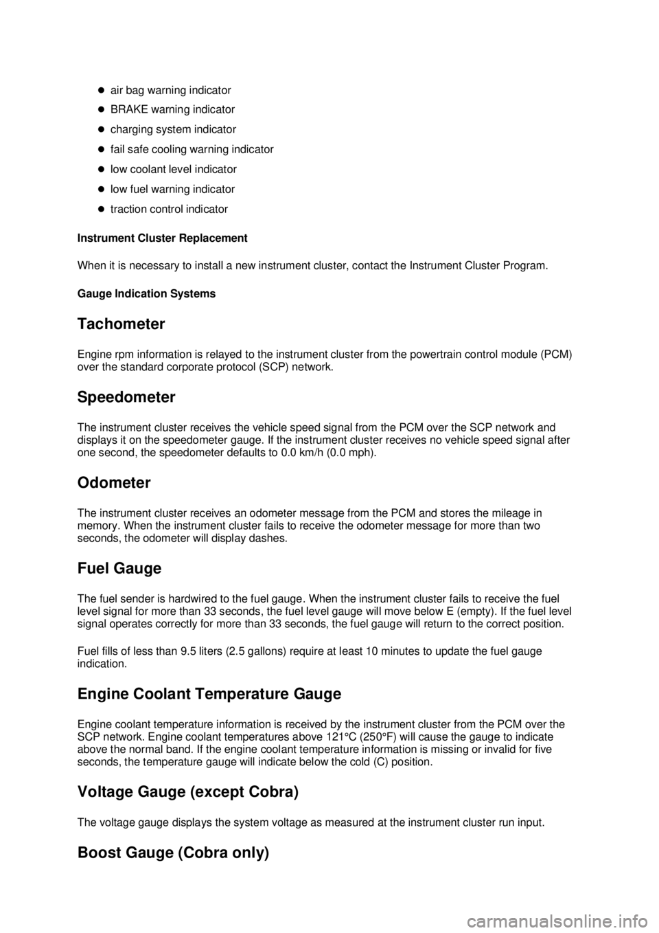
01: Instrument Cluster 2003 Mustang Workshop Manual Special Tool(s)
Worldwide Diagnostic System
(WDS)
418-
F224,
New Generation STAR (NGS)
Tester
418- F052, or equivalent
diagnostic tool Instrument Gauge System
Tester
014-
R1063 or equivalent 73III Automotive Meter
105-
R0057 or equivalent �K�l�j . 1 �b�a
412003 Mustang Workshop Manual
18. 11. 2011file:///C:/Ford/2000 - 2004/tsocache/SHEF_5108/S3B~us~en~ ...
Page 3264 of 4378

�z
air bag warning indicator
�z BRAKE warning indicator
�z charging system indicator
�z fail safe cooling warning indicator
�z low coolant level indicator
�z low fuel warning indicator
�z traction control indicator
Instrument Cluster Replacement
When it is necessary to install a new instrument cluster, contact the Instrument Cluster Program.
Gauge Indication Systems
Tachometer
Engine rpm information is relayed to the instrument cluster from the powertrain control module (PCM)
over the standard corporate protocol (SCP) network.
Speedometer
The instrument cluster receives the vehicle speed signal from the PCM over the SCP network and
displays it on the speedometer gauge. If the instrument cluster receives no vehicle speed signal after
one second, the speedometer defaults to 0.0 km/h (0.0 mph).
Odometer
The instrument cluster receives an odometer message from the PCM and stores the mileage in
memory. When the instrument cluster fails to receive the odometer message for more than two
seconds, the odometer will display dashes.
Fuel Gauge
The fuel sender is hardwired to the fuel gauge. When the instrument cluster fails to receive the fuel
level signal for more than 33 seconds, the fuel level gauge will move below E (empty). If the fuel level
signal operates correctly for more than 33 seconds, the fuel gauge will return to the correct position.
Fuel fills of less than 9.5 liters (2.5 gallons) require at least 10 minutes to update the fuel gauge
indication.
Engine Coolant Temperature Gauge
Engine coolant temperature information is received by the instrument cluster from the PCM over the
SCP network. Engine coolant temperatures above 121°C (250°F) will cause the gauge to indicate
above the normal band. If the engine coolant temperature information is missing or invalid for five
seconds, the temperature gauge will indicate below the cold (C) position.
Voltage Gauge (except Cobra)
The voltage gauge displays the system voltage as measured at the instrument cluster run input. Boost Gauge (Cobra only) �K�l�j . 2 �b�a
412003 Mustang Workshop Manual
18. 11. 2011file:///C:/Ford/2000 - 2004/tsocache/SHEF_5108/S3B~us~en~ ...