Page 1884 of 4378
5. Remove the belt idler bracket support assembly.
All vehicles 6. Drain the engine coolant. For additional information, refer to Cooling System Draining, Filling and Bleeding in this section.
7. Loosen the coolant pump pulley bolts.
8. Remove the accessory drive belt. For additional information, refer to Section 303 - 05 .
9. Remove the bolts and the coolant pump pulley. �K�l�j . 2 �b�a
42003 Mustang Workshop Manual
18. 11. 2011file:///C:/Ford/2000 - 2004/tsocache/SHEF_4464/S3B~us~en~ ...
Page 1885 of 4378
10. Remove the four bolts and the coolant pump.
11. If necessary, wipe the coolant pump mounting surface with a soft cloth.
12.
CAUTION: Do not rotate the coolant pump housing once installed in the engine.
Damage to the O- ring seal can occur, causing the coolant pump to leak.
NOTE: Install a new O- ring seal and lubricate with the same clean engine coolant that is
present in the system. Do not mix coolant types.
To install, reverse the removal procedure. �K�l�j . 3 �b�a
42003 Mustang Workshop Manual
18. 11. 2011file:///C:/Ford/2000 - 2004/tsocache/SHEF_4464/S3B~us~en~ ...
Page 1887 of 4378

REMOVAL AND INSTALLATION
Radiator
Removal and Installation
NOTE:
Radiator removal and installation is similar for both 3.8L and 4.6L vehicles. The art shown in
the procedure is the 4.6L engine.
Mach I
1. Remove the air intake scoop. For additional information, refer to Section 303 - 12 .
All vehicles 2. Drain the engine cooling system. For additional information, refer to Cooling System Draining, Filling and Bleeding in this section.
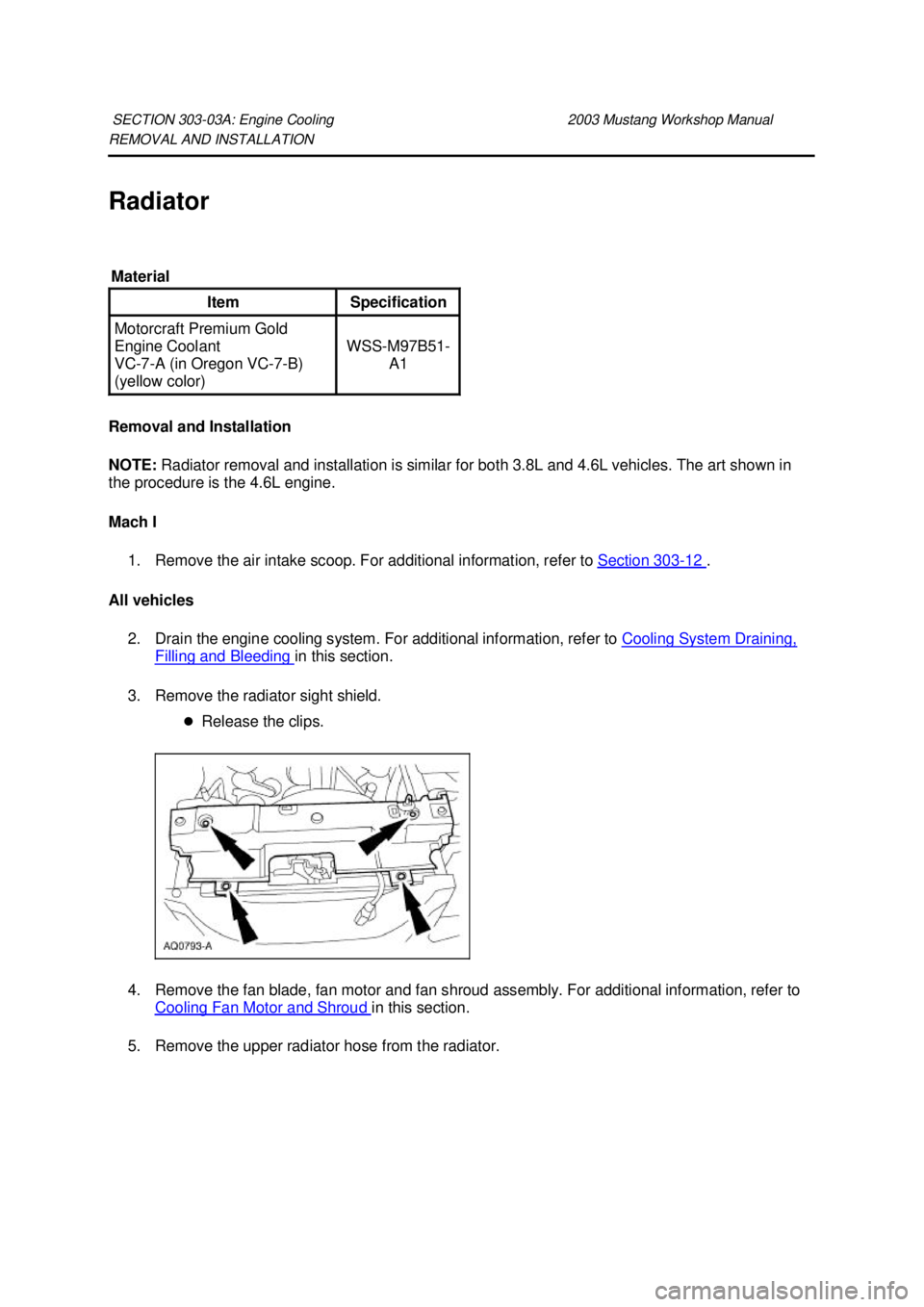
3. Remove the radiator sight shield. �zRelease the clips.
4. Remove the fan blade, fan motor and fan shroud assembly. For additional information, refer to Cooling Fan Motor and Shroud in this section.
5. Remove the upper radiator hose from the radiator.
SECTION 303-
03A: Engine Cooling 2003 Mustang Workshop Manual Material
Item Specification
Motorcraft Premium Gold
Engine Coolant
VC
-7-A (in Oregon VC-7- B)
(yellow color) WSS-
M97B51-
A1 �K�l�j . 1 �b�a
42003 Mustang Workshop Manual
18. 11. 2011file:///C:/Ford/2000 - 2004/tsocache/SHEF_4464/S3B~us~en~ ...
Page 1891 of 4378
REMOVAL AND INSTALLATION
Cooling Fan Motor and Shroud
Removal and Installation
1. Disconnect the battery ground cable.
2. Remove the degas bottle or coolant expansion tank. For additional information, refer to Degas Bottle — 4.6L(2V) and 4.6L(4V) in this section.
3. Disconnect the cooling fan electrical connector.
4. Separate the fan harness from the shroud.
5. Remove the LH bolt. 6. Remove the RH bolt. SECTION 303-
03A: Engine Cooling 2003 Mustang Workshop Manual �K�l�j . 1 �b�a
22003 Mustang Workshop Manual
18. 11. 2011file:///C:/Ford/2000 - 2004/tsocache/SHEF_4464/S3B~us~en~ ...
Page 1893 of 4378
REMOVAL AND INSTALLATION
Water Bypass Hose —
3.8L
Removal and Installation 1. Drain the engine coolant. For additional information, refer to Cooling System Draining, Filling and Bleeding in this section.
2. Remove the bypass hose.
3. To install, reverse the removal procedure.
4. Fill and bleed the cooling system. For additional information, refer to Cooling System Draining, Filling and Bleeding in this section.
SECTION 303-
03A: Engine Cooling 2003 Mustang Workshop Manual �K�l�j . 1 �b�a
12003 Mustang Workshop Manual
18. 11. 2011file:///C:/Ford/2000 - 2004/tsocache/SHEF_4464/S3B~us~en~ ...
Page 1894 of 4378
REMOVAL AND INSTALLATION
Degas Bottle —
4.6L(2V) and 4.6L(4V)
Removal and Installation 1. Drain the engine coolant from the degas bottle only. For additional information, refer to Cooling System Draining, Filling and Bleeding in this section.
2. Disconnect the radiator vent hose.
3. Remove the degas bottle return hose.
4. Remove the nuts and the degas bottle.
5. To install, reverse the removal procedure.
6. Fill and bleed the cooling system. For additional information, refer to Cooling System Draining, Filling and Bleeding in this section.
SECTION 303-
03A: Engine Cooling 2003 Mustang Workshop Manual �K�l�j . 1 �b�a
22003 Mustang Workshop Manual
18. 11. 2011file:///C:/Ford/2000 - 2004/tsocache/SHEF_4464/S3B~us~en~ ...
Page 1896 of 4378

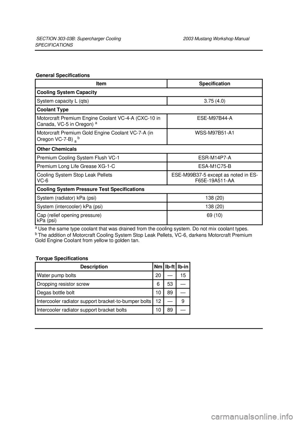
SPECIFICATIONS
a
Use the same type coolant that was drained from the cooling system. Do not mix coolant types.
b The addition of Motorcraft Cooling System Stop Leak Pellets, VC- 6, darkens Motorcraft Premium
Gold Engine Coolant from yellow to golden tan. SECTION 303-
03B: Supercharger Cooling 2003 Mustang Workshop Manual General Specifications
Item Specification
Cooling System Capacity
System capacity L (qts) 3.75 (4.0)
Coolant Type
Motorcraft Premium Engine Coolant VC-4-
A (CXC-10 in
Canada, VC- 5 in Oregon) a ESE-
M97B44- A Motorcraft Premium Gold Engine Coolant VC-7-
A (in
Oregon VC-7- B)
a b WSS-
M97B51- A1 Other Chemicals
Premium Cooling System Flush VC-
1 ESR-
M14P7-A Premium Long Life Grease XG-1-
C ESA-
M1C75- B Cooling System Stop Leak Pellets
VC-
6 ESE-
M99B37- 5 except as noted in ES-
F65E-19A511- AA Cooling System Pressure Test Specifications
System (radiator) kPa (psi) 138 (20)
System (intercooler) kPa (psi) 138 (20)
Cap (relief opening pressure)
kPa (psi) 69 (10)
Torque Specifications Description Nm lb-
ft lb-
in Water pump bolts 20 — 15
Dropping resistor screw 6 53 —
Degas bottle bolt 10 89 —
Intercooler radiator support bracket-
to-bumper bolts 12 — 9
Intercooler radiator support bracket bolts 10 89 — �K�l�j . 1 �b�a
22003 Mustang Workshop Manual
18. 11. 2011file:///C:/Ford/2000 - 2004/tsocache/SHEF_4464/S3B~us~en~ ...
Page 1898 of 4378

DESCRIPTION AND OPERATION
Supercharger Cooling
CAUTION: Some vehicle cooling systems are filled with Motorcraft Premium Engine
Coolant VC -4-A (in Oregon VC- 5, in Canada CXC- 10) or equivalent meeting Ford specification
ESE- M97B44- A (green color). Others are filled with Motorcraft Premium Gold Engine Coolant
VC -7-A or equivalent meeting Ford specification WSS- M97B51-A1 (yellow color). Always fill the
cooling system with the same coolant that is present in the system. Do not mix coolant types.
NOTE: The addition of Motorcraft Cooling System Stop Leak Pellets, VC- 6, darkens Motorcraft
Premium Gold Engine Coolant from yellow to golden tan.
NOTE: The air that is produced from the supercharger is cooled by the intercooler.
Walter C. Avrea, the owner of patents 3,601,181 and RE 27,965, has granted Ford Motor Company
rights with respect to cooling systems covered by these patents.
The cooling system components include the:
�zintercooler
�z intercooler radiator (8K226)
�z pressure relief cap
�z degas bottle
�z electric water pump (8501)
The degas bottle:
�zprovides a location for system fill.
�z contains coolant expansion and system pressurization.
�z provides air separation during operation.
�z replenishes the intercooler coolant to the system.
The intercooler coolant flows:
�zfrom the intercooler to the degas bottle.
�z from the degas bottle to the water pump.
�z from the water pump to the intercooler radiator.
�z from the intercooler radiator to the intercooler.
Engine coolant provides freeze protection, boil protection, cooling efficiency and corrosion protection to
the engine and cooling components. In order to obtain these protections, the engine coolant must be
maintained at the correct concentration and fluid level in the degas bottle.
When adding engine coolant, use a 50/50 mixture of engine coolant and clean, drinkable water.
To maintain the integrity of the coolant and the cooling system: SECTION 303-
03B: Supercharger Cooling 2003 Mustang Workshop Manual �K�l�j . 1 �b�a
22003 Mustang Workshop Manual
18. 11. 2011file:///C:/Ford/2000 - 2004/tsocache/SHEF_4464/S3B~us~en~ ...