Page 1908 of 4378

1. To maintain the integrity of the coolant and the cooling system:
1. Add Motorcraft Premium Engine Coolant VC-4- A (in Oregon VC-5, in Canada CXC-10)
or equivalent meeting Ford specification ESE-M97B44- A (green color), or Motorcraft
Premium Gold Engine Coolant VC-7- A or equivalent meeting Ford specification WSS-
M97B51- A1 (yellow color). Use the same coolant that was drained from the cooling
system. Do not mix coolant types.
2. Do not add/mix orange-colored Motorcraft Speciality Orange Engine Coolant VC- 2 or
equivalent meeting Ford specification WSS-M97B44- D. Mixing coolants may degrade the
coolant's corrosion protection.
3. Do not add alcohol, methanol, brine, or any engine coolants mixed with alcohol or
methanol antifreeze. These can cause engine damage from overheating or freezing.
4. Do not mix with recycled coolant unless it meets the requirements of Ford specification ESE- M97B44- A or WSS-M97B51- A1. Not all coolant recycling processes meet these
Ford specifications. Use of such coolants can harm the engine and cooling system
components.
2. Fill the degas bottle. Use Motorcraft Premium Engine Coolant VC-4- A (in Oregon VC-5, in
Canada CXC- 10) or equivalent meeting Ford specification ESE-M97B44- A (green color), or
Motorcraft Premium Gold Engine Coolant VC-7- A or equivalent meeting Ford specification
WSS- M97B51- A1 (yellow color). Use the same coolant that was drained from the cooling
system. Do not mix coolant types.
3. Start the engine and allow to run until coolant circulation is observed in the intercooler degas bottle. Absence of circulation indicates air is trapped in the system.
�zTurn the engine off.
4. Add coolant as needed. Use Motorcraft Premium Engine Coolant VC -4-A (in Oregon VC-5, in
Canada CXC- 10) or equivalent meeting Ford specification ESE-M97B44- A (green color), or
Motorcraft Premium Gold Engine Coolant VC-7- A or equivalent meeting Ford specification
WSS- M97B51- A1 (yellow color). Use the same coolant that was drained from the cooling
system. Do not mix coolant types.
5. Repeat the above procedure to make sure all entrapped air is released. �K�l�j . 2 �b�a
22003 Mustang Workshop Manual
18. 11. 2011file:///C:/Ford/2000 - 2004/tsocache/SHEF_4464/S3B~us~en~ ...
Page 1909 of 4378

GENERAL PROCEDURES
Supercharger Cooling System Flushing
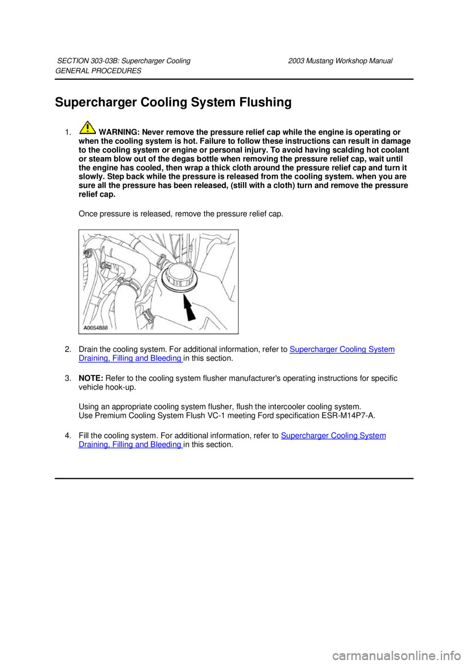
1. WARNING: Never remove the pressure relief cap while the engine is operating or
when the cooling system is hot. Failure to follow these instructions can result in damage
to the cooling system or engine or personal injury. To avoid having scalding hot coolant
or steam blow out of the degas bottle when removing the pressure relief cap, wait until
the engine has cooled, then wrap a thick cloth around the pressure relief cap and turn it
slowly. Step back while the pressure is released from the cooling system. when you are
sure all the pressure has been released, (still with a cloth) turn and remove the pressure
relief cap.
Once pressure is released, remove the pressure relief cap.
2. Drain the cooling system. For additional information, refer to Supercharger Cooling System Draining, Filling and Bleeding in this section.
3. NOTE: Refer to the cooling system flusher manufacturer's operating instructions for specific
vehicle hook- up.
Using an appropriate cooling system flusher, flush the intercooler cooling system.
Use Premium Cooling System Flush VC- 1 meeting Ford specification ESR-M14P7-A.
4. Fill the cooling system. For additional information, refer to Supercharger Cooling System Draining, Filling and Bleeding in this section.
SECTION 303-
03B: Supercharger Cooling 2003 Mustang Workshop Manual �K�l�j . 1 �b�a
22003 Mustang Workshop Manual
18. 11. 2011file:///C:/Ford/2000 - 2004/tsocache/SHEF_4464/S3B~us~en~ ...
Page 1936 of 4378
12 — Coolant reservoir bottle electrical connector
13 — Radio ignition interference capacitor electrical
connector
14 — Fuel injector electrical connectors
15 — Exhaust vacuum regulator (EVR) electrical
connector
16 — Differential pressure feedback EGR electrical
connector
17 — RH ignition coil electrical connectors
18 — Ignition coil electrical connectors
19 — Throttle position (TP) sensor electrical connector
20 — Idle air control (IAC) solenoid electrical connector
21 — Voltage regulator electrical connector
22 — Engine coolant temperature (ECT) electrical
connector
23 — Generator battery electrical connector
24 — Radio ignition interference capacitor electrical
connector
25 — Crankshaft position (CKP) sensor electrical
connector
26 — Air conditioning compressor clutch electrical
connector
27 — 16 pin electrical connector �K�l�j . 3 �b�a
32003 Mustang Workshop Manual
18. 11. 2011file:///C:/Ford/2000 - 2004/tsocache/SHEF_4464/S3B~us~en~ ...
Page 1944 of 4378
6. Disconnect the following connections:
�zFour ignition coils
�z Four fuel injectors
�z Positive crankcase ventilation (PCV) hose from valve cover.
7. Disconnect the following connectors: �zRH radio ignition interference capacitor
�z Engine coolant temperature (ECT) sensor 8. Disconnect the 16 pin connector �K�l�j . 2 �b�a
142003 Mustang Workshop Manual
18. 11. 2011file:///C:/Ford/2000 - 2004/tsocache/SHEF_4464/S3B~us~en~ ...
Page 1972 of 4378
6. Remove the PCV valve.
7. Disconnect and remove the PCV hose.
8. Disconnect the camshaft position (CMP) sensor electrical connector.
9. Disconnect the engine coolant temperature (ECT) sensor electrical connector and unclip the
harness from the stud. �K�l�j . 2 �b�a
72003 Mustang Workshop Manual
18. 11. 2011file:///C:/Ford/2000 - 2004/tsocache/SHEF_4464/S3B~us~en~ ...
Page 1985 of 4378

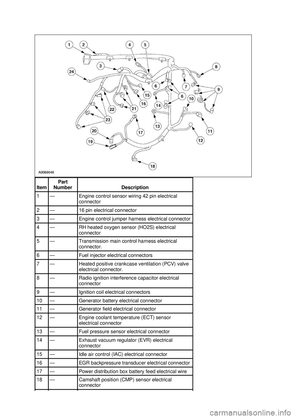
Item Part
Number Description
1 — Engine control sensor wiring 42 pin electrical
connector
2 — 16 pin electrical connector
3 — Engine control jumper harness electrical connector
4 — RH heated oxygen sensor (HO2S) electrical
connector
5 — Transmission main control harness electrical
connector.
6 — Fuel injector electrical connectors
7 — Heated positive crankcase ventilation (PCV) valve
electrical connector.
8 — Radio ignition interference capacitor electrical
connector
9 — Ignition coil electrical connectors
10 — Generator battery electrical connector
11 — Generator field electrical connector
12 — Engine coolant temperature (ECT) sensor
electrical connector
13 — Fuel pressure sensor electrical connector
14 — Exhaust vacuum regulator (EVR) electrical
connector
15 — Idle air control (IAC) electrical connector
16 — EGR backpressure transducer electrical connector
17 — Power distribution box battery feed electrical wire
18 — Camshaft position (CMP) sensor electrical
connector �K�l�j . 2 �b�a
32003 Mustang Workshop Manual
18. 11. 2011file:///C:/Ford/2000 - 2004/tsocache/SHEF_4464/S3B~us~en~ ...
Page 1997 of 4378
18. Disconnect the electrical connector.
19. Disconnect the following generator electrical connectors:
�zBattery power supply wire.
�z Voltage regulator.
20. Disconnect the camshaft position (CMP) sensor electrical connector.
21. Disconnect the engine coolant temperature (ECT) sensor electrical connector. �K�l�j . 5 �b�a
112003 Mustang Workshop Manual
18. 11. 2011file:///C:/Ford/2000 - 2004/tsocache/SHEF_4464/S3B~us~en~ ...
Page 2014 of 4378

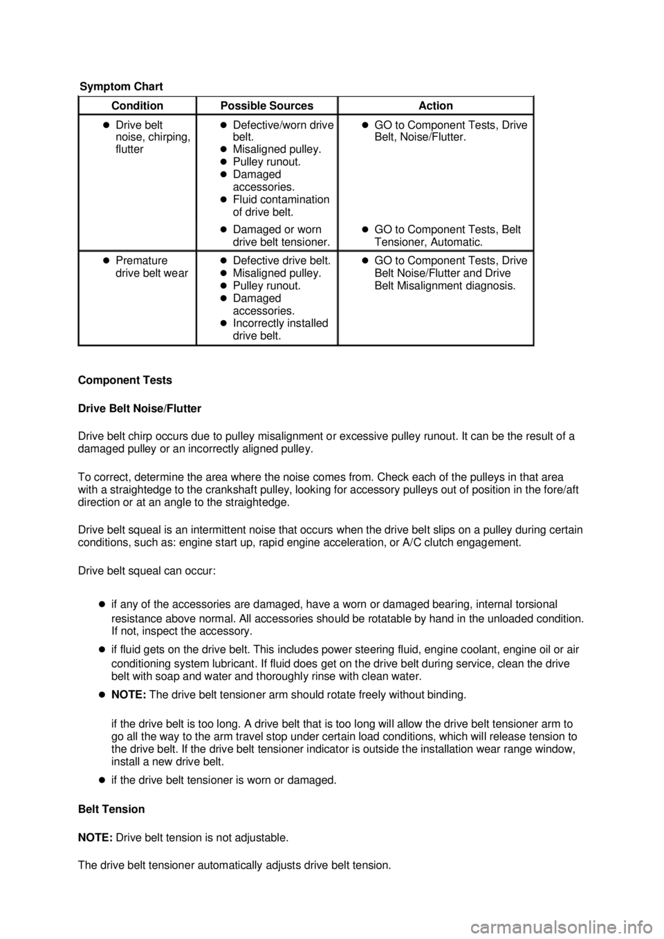
Component Tests
Drive Belt Noise/Flutter
Drive belt chirp occurs due to pulley misalignment or excessive pulley runout. It can be the result of a
damaged pulley or an incorrectly aligned pulley.
To correct, determine the area where the noise comes from. Check each of the pulleys in that area
with a straightedge to the crankshaft pulley, looking for accessory pulleys out of position in the fore/aft
direction or at an angle to the straightedge.
Drive belt squeal is an intermittent noise that occurs when the drive belt slips on a pulley during certain
conditions, such as: engine start up, rapid engine acceleration, or A/C clutch engagement.
Drive belt squeal can occur:
�zif any of the accessories are damaged, have a worn or damaged bearing, internal torsional
resistance above normal. All accessories should be rotatable by hand in the unloaded condition.
If not, inspect the accessory.
�z if fluid gets on the drive belt. This includes power steering fluid, engine coolant, engine oil or air
conditioning system lubricant. If fluid does get on the drive belt during service, clean the drive
belt with soap and water and thoroughly rinse with clean water.
�z NOTE: The drive belt tensioner arm should rotate freely without binding.
if the drive belt is too long. A drive belt that is too long will allow the drive belt tensioner arm to
go all the way to the arm travel stop under certain load conditions, which will release tension to
the drive belt. If the drive belt tensioner indicator is outside the installation wear range window,
install a new drive belt.
�z if the drive belt tensioner is worn or damaged.
Belt Tension
NOTE: Drive belt tension is not adjustable.
The drive belt tensioner automatically adjusts drive belt tension. Symptom Chart Condition
Possible Sources Action
�z Drive belt
noise, chirping,
flutter �z
Defective/worn drive
belt.
�z Misaligned pulley.
�z Pulley runout.
�z Damaged
accessories.
�z Fluid contamination
of drive belt. �z
GO to Component Tests, Drive
Belt, Noise/Flutter.
�z Damaged or worn
drive belt tensioner. �z
GO to Component Tests, Belt
Tensioner, Automatic.
�z Premature
drive belt wear �z
Defective drive belt.
�z Misaligned pulley.
�z Pulley runout.
�z Damaged
accessories.
�z Incorrectly installed
drive belt. �z
GO to Component Tests, Drive
Belt Noise/Flutter and Drive
Belt Misalignment diagnosis. �K�l�j . 2 �b�a
42003 Mustang Workshop Manual
18. 11. 2011file:///C:/Ford/2000 - 2004/tsocache/SHEF_4464/S3B~us~en~ ...