Page 3360 of 4378
4. With the engine running, turn the A/C on, the blower motor on high speed and the headlamps
on high beam.
5. Increase the engine speed to approximately 2,000 rpm. The voltage should increase a minimum of 0.5 volt above the base voltage.
�zIf the voltage does not increase as specified, carry out the Generator On- Vehicle Tests—
No Load Test. For additional information, refer to Generator On- Vehicle Tests in this
section.
�z If the voltage increases as specified, the charging system is operating normally.
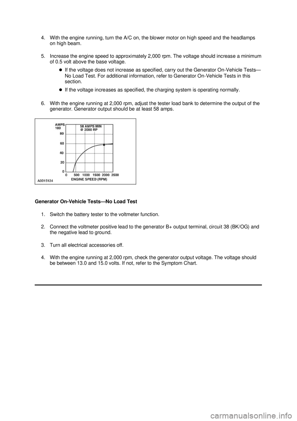
6. With the engine running at 2,000 rpm, adjust the tester load bank to determine the output of the generator. Generator output should be at least 58 amps.
Generator On- Vehicle Tests— No Load Test
1. Switch the battery tester to the voltmeter function.
2. Connect the voltmeter positive lead to the generator B+ output terminal, circuit 38 (BK/OG) and the negative lead to ground.
3. Turn all electrical accessories off.
4. With the engine running at 2,000 rpm, check the generator output voltage. The voltage should be between 13.0 and 15.0 volts. If not, refer to the Symptom Chart. �K�l�j . 13 �b�a
142003 Mustang Workshop Manual
18. 11. 2011file:///C:/Ford/2000 - 2004/tsocache/SHEF_5108/S3B~us~en~ ...
Page 3362 of 4378
SPECIFICATIONS
SECTION 414-
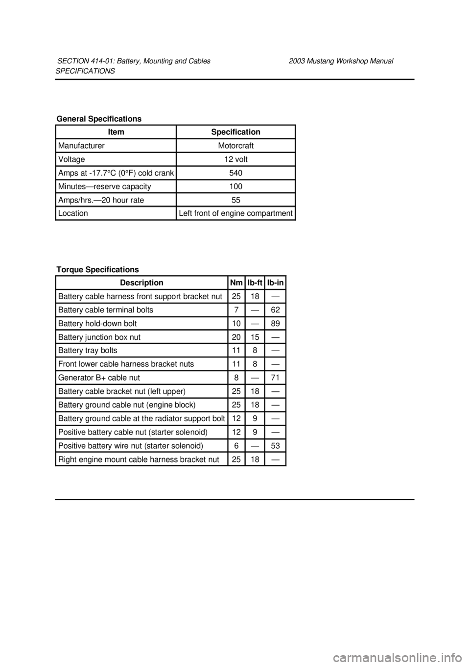
01: Battery, Mounting and Cables 2003 Mustang Workshop Manual General Specifications
Item Specification
Manufacturer Motorcraft
Voltage 12 volt
Amps at -
17.7°C (0°F) cold crank 540
Minutes—
reserve capacity 100
Amps/hrs.—20 hour rate 55
Location Left front of engine compartment
Torque Specifications Description Nm lb-
ft lb-
in Battery cable harness front support bracket nut 25 18 —
Battery cable terminal bolts 7 — 62
Battery hold-
down bolt 10 — 89
Battery junction box nut 20 15 —
Battery tray bolts 11 8 —
Front lower cable harness bracket nuts 11 8 —
Generator B+ cable nut 8 — 71
Battery cable bracket nut (left upper) 25 18 —
Battery ground cable nut (engine block) 25 18 —
Battery ground cable at the radiator support bolt 12 9 —
Positive battery cable nut (starter solenoid) 12 9 —
Positive battery wire nut (starter solenoid) 6 — 53
Right engine mount cable harness bracket nut 25 18 — �K�l�j . 1 �b�a
22003 Mustang Workshop Manual
18. 11. 2011file:///C:/Ford/2000 - 2004/tsocache/SHEF_5108/S3B~us~en~ ...
Page 3375 of 4378
REMOVAL AND INSTALLATION
Battery Cables
Removal
WARNING: Batteries normally produce explosive gases which can cause personal injury.
Therefore, do not allow flames, sparks or lighted substances to come near the battery. When
charging or working near a battery, always shield your face and protect your eyes. Always
provide ventilation. Failure to follow these instructions may result in personal injury.
WARNING: Keep out of the reach of children. Batteries contain sulfuric acid. Avoid
contact with skin, eyes, or clothing. Also, shield your eyes when working near the battery to
protect against possible splashing of the acid solution. In case of acid contact with skin or
eyes, flush immediately with water for a minimum of 15 minutes and get prompt medical
attention. If acid is swallowed, call a physician immediately. Failure to follow these instructions
may result in personal injury.
All vehicles
1. Remove the battery. For additional information, refer to Battery in this section.
2. If equipped, unplug the engine heater intermediate connection.
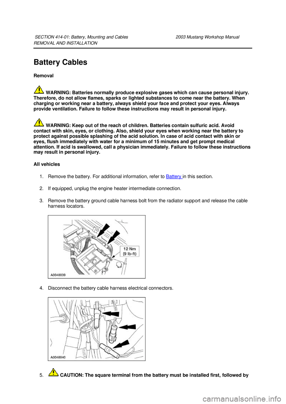
3. Remove the battery ground cable harness bolt from the radiator support and release the cable harness locators.
4. Disconnect the battery cable harness electrical connectors.
5. CAUTION: The square terminal from the battery must be installed first, followed by
SECTION 414-
01: Battery, Mounting and Cables 2003 Mustang Workshop Manual �K�l�j . 1 �b�a
62003 Mustang Workshop Manual
18. 11. 2011file:///C:/Ford/2000 - 2004/tsocache/SHEF_5108/S3B~us~en~ ...
Page 3376 of 4378
the round terminal from the generator. Reversing this sequence may cause circuit failure
or arcing.
Remove the battery junction box nut and position the positive battery cable and generator B+
cable aside.
Vehicles with 3.8L and 4.6L 2V engines 6. Remove the cable harness front support bracket by removing the nut, and position the bracket aside.
Vehicles with 4.6L 4V engines 7. Remove the nut and position the left upper battery cable bracket aside.
All vehicles 8. Raise and support the vehicle. For additional information, refer to Section 100 - 02 .
9. NOTE: 4.6L 4V shown; 3.8L and 4.6L 2V similar.
If equipped, remove the block heater plug from the block heater and the harness locators from �K�l�j . 2 �b�a
62003 Mustang Workshop Manual
18. 11. 2011file:///C:/Ford/2000 - 2004/tsocache/SHEF_5108/S3B~us~en~ ...
Page 3377 of 4378
the oil pan clips.
10. NOTE: 4.6L 4V shown; 3.8L and 4.6L 2V similar.
Disconnect the oil pressure sender unit electrical connector.
11. CAUTION: Failure to tighten the negative cable ground nut may cause ground
circuit failure or arcing.
NOTE: 4.6L 2V shown; 3.8L and 4.6L 4V similar.
Remove the battery ground cable nut at the engine block.
12. Remove the nut and disconnect the generator electrical connections. �zPosition the cover aside. �K�l�j . 3 �b�a
62003 Mustang Workshop Manual
18. 11. 2011file:///C:/Ford/2000 - 2004/tsocache/SHEF_5108/S3B~us~en~ ...
Page 3378 of 4378
13.
NOTE: 4.6L 2V shown; 3.8L and 4.6L 4V similar.
Remove the front lower cable harness bracket nuts.
14. Pull the harness assembly downward until it clears the engine/radiator area.
15. NOTE: 4.6L 2V shown; 3.8L and 4.6L 4V similar.
Remove the right engine mount cable harness bracket nut.
16. Remove the cover from the starter solenoid connections. �K�l�j . 4 �b�a
62003 Mustang Workshop Manual
18. 11. 2011file:///C:/Ford/2000 - 2004/tsocache/SHEF_5108/S3B~us~en~ ...
Page 3391 of 4378
DIAGNOSIS AND TESTING
Audio System
Refer to Wiring Diagrams Cell
130 , Radio for schematic and connector information.
Inspection and Verification 1. Verify the customer concern by operating the electronic audio system with the engine running.
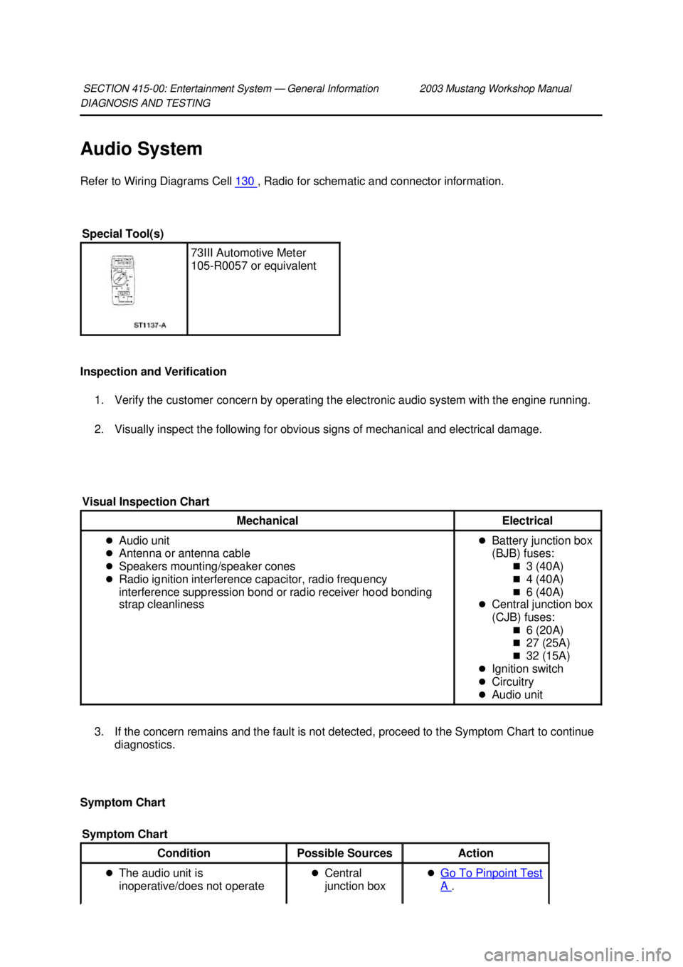
2. Visually inspect the following for obvious signs of mechanical and electrical damage.
3. If the concern remains and the fault is not detected, proceed to the Symptom Chart to continue diagnostics.
Symptom Chart SECTION 415-
00: Entertainment System — General Information 2003 Mustang Workshop Manual Special Tool(s)
73III Automotive Meter
105-
R0057 or equivalent
Visual Inspection Chart Mechanical Electrical
�z
Audio unit
�z Antenna or antenna cable
�z Speakers mounting/speaker cones
�z Radio ignition interference capacitor, radio frequency
interference suppression bond or radio receiver hood bonding
strap cleanliness �z
Battery junction box
(BJB) fuses:
�„3 (40A)
�„ 4 (40A)
�„ 6 (40A)
�z Central junction box
(CJB) fuses:
�„6 (20A)
�„ 27 (25A)
�„ 32 (15A)
�z Ignition switch
�z Circuitry
�z Audio unit
Symptom Chart Condition
Possible Sources Action
�z The audio unit is
inoperative/does not operate �z
Central
junction box �z
Go To Pinpoint Test A . �K�l�j . 1 �b�a
242003 Mustang Workshop Manual
18. 11. 2011file:///C:/Ford/2000 - 2004/tsocache/SHEF_5108/S3B~us~en~ ...
Page 3396 of 4378
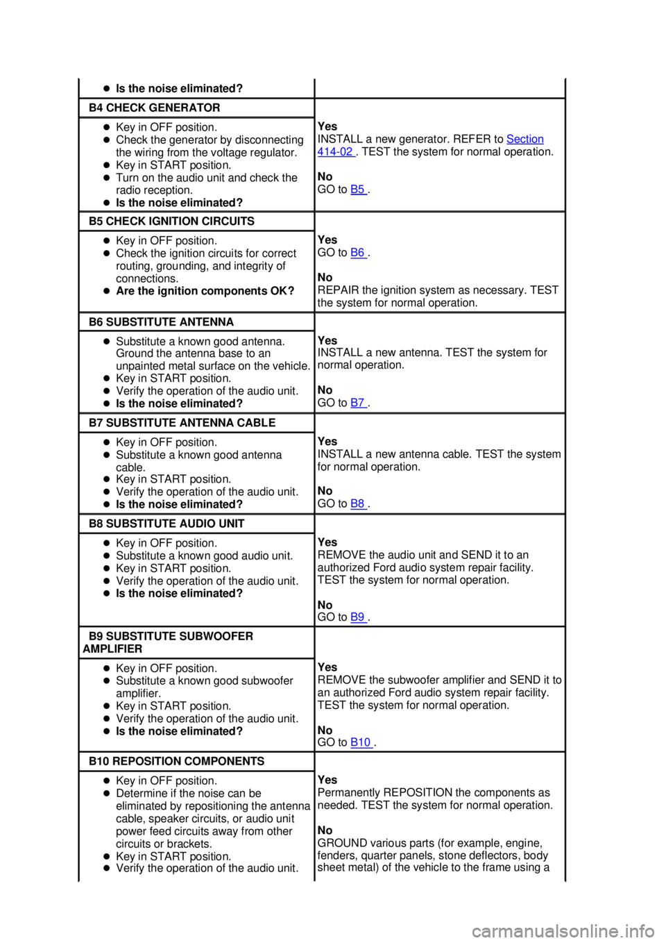
�z
Is the noise eliminated? B4 CHECK GENERATOR
�z
Key in OFF position.
�z Check the generator by disconnecting
the wiring from the voltage regulator.
�z Key in START position.
�z Turn on the audio unit and check the
radio reception.
�z Is the noise eliminated? Yes
INSTALL a new generator. REFER to
Section 414 - 02 . TEST the system for normal operation.
No
GO to B5 .
B5 CHECK IGNITION CIRCUITS
�z
Key in OFF position.
�z Check the ignition circuits for correct
routing, grounding, and integrity of
connections.
�z Are the ignition components OK? Yes
GO to
B6 .
No
REPAIR the ignition system as necessary. TEST
the system for normal operation. B6 SUBSTITUTE ANTENNA
�z
Substitute a known good antenna.
Ground the antenna base to an
unpainted metal surface on the vehicle.
�z Key in START position.
�z Verify the operation of the audio unit.
�z Is the noise eliminated? Yes
INSTALL a new antenna. TEST the system for
normal operation.
No
GO to
B7 .
B7 SUBSTITUTE ANTENNA CABLE
�z
Key in OFF position.
�z Substitute a known good antenna
cable.
�z Key in START position.
�z Verify the operation of the audio unit.
�z Is the noise eliminated? Yes
INSTALL a new antenna cable. TEST the system
for normal operation.
No
GO to
B8 .
B8 SUBSTITUTE AUDIO UNIT
�z
Key in OFF position.
�z Substitute a known good audio unit.
�z Key in START position.
�z Verify the operation of the audio unit.
�z Is the noise eliminated? Yes
REMOVE the audio unit and SEND it to an
authorized Ford audio system repair facility.
TEST the system for normal operation.
No
GO to
B9 .
B9 SUBSTITUTE SUBWOOFER
AMPLIFIER �z
Key in OFF position.
�z Substitute a known good subwoofer
amplifier.
�z Key in START position.
�z Verify the operation of the audio unit.
�z Is the noise eliminated? Yes
REMOVE the subwoofer amplifier and SEND it to
an authorized Ford audio system repair facility.
TEST the system for normal operation.
No
GO to
B10 .
B10 REPOSITION COMPONENTS
�z
Key in OFF position.
�z Determine if the noise can be
eliminated by repositioning the antenna
cable, speaker circuits, or audio unit
power feed circuits away from other
circuits or brackets.
�z Key in START position.
�z Verify the operation of the audio unit. Yes
Permanently REPOSITION the components as
needed. TEST the system for normal operation.
No
GROUND various parts (for example, engine,
fenders, quarter panels, stone deflectors, body
sheet metal) of the vehicle to the frame using a �K�l�j . 6 �b�a
242003 Mustang Workshop Manual
18. 11. 2011file:///C:/Ford/2000 - 2004/tsocache/SHEF_5108/S3B~us~en~ ...