2003 DODGE RAM engine
[x] Cancel search: enginePage 1715 of 2895
INSTALLATION
3.7L V-6
(1) If fuel injectors are to be installed, refer to Fuel
Injector Removal/Installation.
(2) Clean out fuel injector machined bores in
intake manifold.
(3) Apply a small amount of engine oil to each fuel
injector o-ring. This will help in fuel rail installation.
(4) Position fuel rail/fuel injector assembly to
machined injector openings in cylinder head.
(5) Guide each injector into cylinder head. Be care-
ful not to tear injector o-rings.
(6) Pushrightside of fuel rail down until fuel
injectors have bottomed on cylinder head shoulder.
Pushleftfuel rail down until injectors have bot-
tomed on cylinder head shoulder.
(7) Install 4 fuel rail mounting bolts and tighten.
Refer to torque specifications.
(8) Install 6 ignition coils. Refer to Ignition Coil
Removal/Installation.
(9) Connect electrical connectors to throttle body.
(10) Connect electrical connectors at all fuel injec-
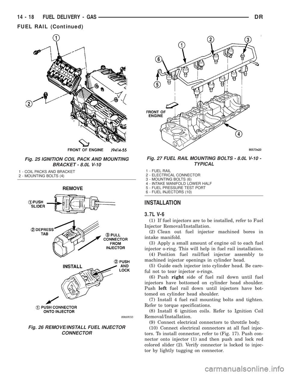
tors. To install connector, refer to (Fig. 17). Push con-
nector onto injector (1) and then push and lock red
colored slider (2). Verify connector is locked to injec-
tor by lightly tugging on connector.
Fig. 25 IGNITION COIL PACK AND MOUNTING
BRACKET - 8.0L V-10
1 - COIL PACKS AND BRACKET
2 - MOUNTING BOLTS (4)
Fig. 26 REMOVE/INSTALL FUEL INJECTOR
CONNECTOR
Fig. 27 FUEL RAIL MOUNTING BOLTS - 8.0L V-10 -
TYPICAL
1 - FUEL RAIL
2 - ELECTRICAL CONNECTOR
3 - MOUNTING BOLTS (6)
4 - INTAKE MANIFOLD LOWER HALF
5 - FUEL PRESSURE TEST PORT
6 - FUEL INJECTORS (10)
14 - 18 FUEL DELIVERY - GASDR
FUEL RAIL (Continued)
Page 1716 of 2895
(11) Connect necessary vacuum lines to throttle
body.
(12) Install air resonator mounting bracket near
front of throttle body (2 bolts).
(13) Connect fuel line latch clip and fuel line to
fuel rail. Refer to Quick-Connect Fittings.
(14) Install air box to throttle body.
(15) Install air duct to air box.
(16) Connect battery cable to battery.
(17) Start engine and check for leaks.
4.7L V-8
(1) If fuel injectors are to be installed, refer to Fuel
Injector Removal/Installation.
(2) Clean out fuel injector machined bores in
intake manifold.
(3) Apply a small amount of engine oil to each fuel
injector o-ring. This will help in fuel rail installation.
(4) Position fuel rail/fuel injector assembly to
machined injector openings in cylinder head.
(5) Guide each injector into cylinder head. Be care-
ful not to tear injector o-rings.
(6) Pushrightside of fuel rail down until fuel
injectors have bottomed on cylinder head shoulder.
Pushleftfuel rail down until injectors have bot-
tomed on cylinder head shoulder.
(7) Install 4 fuel rail mounting bolts and tighten.
Refer to torque specifications.
(8) Install 8 ignition coils. Refer to Ignition Coil
Removal/Installation.
(9) Connect electrical connectors to throttle body.
(10) Connect electrical connectors at all fuel injec-
tors. To install connector, refer to (Fig. 17). Push con-
nector onto injector (1) and then push and lock red
colored slider (2). Verify connector is locked to injec-
tor by lightly tugging on connector.
(11) Connect necessary vacuum lines to throttle
body.
(12) Install air resonator mounting bracket near
front of throttle body (2 bolts).
(13) Connect fuel line latch clip and fuel line to
fuel rail. Refer to Quick-Connect Fittings.
(14) Install air box to throttle body.
(15) Install air duct to air box.
(16) Connect battery cable to battery.
(17) Start engine and check for leaks.
5.7L V-8
(1) If fuel injectors are to be installed, refer to Fuel
Injector Removal/Installation.
(2) Clean out fuel injector machined bores in
intake manifold.
(3) Apply a small amount of engine oil to each fuel
injector o-ring. This will help in fuel rail installation.
(4) Position fuel rail/fuel injector assembly to
machined injector openings in intake manifold.(5) Guide each injector into intake manifold. Be
careful not to tear injector o-rings.
(6) Pushrightside of fuel rail down until fuel
injectors have bottomed on shoulders. Pushleftfuel
rail down until injectors have bottomed on shoulders.
(7) Install 4 fuel rail holdown clamps and 4 mount-
ing bolts. Refer to Torque Specifications.
(8) Position spark plug cable tray and cable assem-
bly to intake manifold. Snap 4 cable tray retaining
clips into intake manifold.
(9) Install all cables to spark plugs and ignition
coils.
(10) Connect electrical connector to throttle body.
(11) Install electrical connectors to all 8 ignition
coils. Refer to Ignition Coil Removal/Installation.
(12) Connect electrical connector to throttle body.
(13) Connect electrical connectors at all fuel injec-
tors. To install connector, refer to (Fig. 17). Push con-
nector onto injector (1) and then push and lock red
colored slider (2). Verify connector is locked to injec-
tor by lightly tugging on connector.
(14) Connect fuel line latch clip and fuel line to
fuel rail. Refer to Quick-Connect Fittings.
(15) Install air resonator to throttle body (2 bolts).
(16) Install flexible air duct to air box.
(17) Connect battery cable to battery.
(18) Start engine and check for leaks.
5.9L V-8
(1) If fuel injectors are to be installed, refer to Fuel
Injector Removal/Installation.
(2) Apply a small amount of engine oil to each fuel
injector o-ring. This will help in fuel rail installation.
(3) Clean out fuel injector machined bores in
intake manifold.
(4) Position fuel rail/fuel injector assembly to injec-
tor openings on intake manifold.
(5) Guide each injector into intake manifold. Be
careful not to tear injector o-ring.
(6) Push therightfuel rail down until fuel injec-
tors have bottomed on injector shoulder. Push the
leftfuel rail down until fuel injectors have bottomed
on injector shoulder.
(7) Install fuel rail mounting bolts. Refer to Torque
Specifications.
(8) Connect electrical connector to intake manifold
air temperature sensor.
(9) Connect electrical connectors at all fuel injec-
tors. To install connector, refer to (Fig. 17). Push con-
nector onto injector (1) and then push and lock red
colored slider (2). Verify connector is locked to injec-
tor by lightly tugging on connector.
(10) Install fuel tube (line) at side of fuel rail.
Refer to Quick-Connect Fittings for procedures.
(11) Install air cleaner resonator to throttle body.
(12) Connect battery cable to battery.
DRFUEL DELIVERY - GAS 14 - 19
FUEL RAIL (Continued)
Page 1717 of 2895
(13) Start engine and check for leaks.
8.0L V-10
(1) Apply a small amount of engine oil to each fuel
injector o-ring. This will help in fuel rail installation.
(2) Install injector(s) and injector clip(s) to fuel
rail.
NOTE: The fuel injector electrical connectors on all
10 injectors should be facing to right (passenger)
side of vehicle (Fig. 27).
(3) Position fuel rail/fuel injector assembly to injec-
tor openings on intake manifold.
(4) Guide each injector into intake manifold. Be
careful not to tear injector o-ring.
(5) Push therightfuel rail down until fuel injec-
tors have bottomed on injector shoulder. Push the
leftfuel rail down until fuel injectors have bottomed
on injector shoulder.
(6) Install six fuel rail mounting bolts into lower
half of intake manifold. Tighten bolts to 15 N´m (136
in. lbs.) torque.
(7) Connect electrical connectors at all fuel injec-
tors. To install connector, refer to (Fig. 26). Push con-
nector onto injector (1) and then push and lock red
colored slider (2). Verify connector is locked to injec-
tor by lightly tugging on connector. The injector wir-
ing harness is numerically tagged.
(8) Install upper half of intake manifold. Refer to
Engines for procedures.
(9) Connect main fuel line at fuel rail. Refer to
Quick-Connect Fittings for procedures.
(10) Install ignition coil pack and bracket assem-
bly at intake manifold and right engine valve cover
(four bolts).
(11) Install throttle body to intake manifold. Refer
to Throttle Body Removal / Installation.
(12) Install throttle body linkage to throttle body.
(13) Install air cleaner tube and housing.
(14) Install negative battery cable at battery.
(15) Start engine and check for leaks.
FUEL TANK
DESCRIPTION
The fuel tank is constructed of a plastic material.
Its main functions are for fuel storage and for place-
ment of the fuel pump module, and (if equipped) cer-
tain ORVR components.
OPERATION
All models pass a full 360 degree rollover test
without fuel leakage. To accomplish this, fuel and
vapor flow controls are required for all fuel tank con-
nections.Two check (control) valves are mounted into the
top of the fuel tank. Refer to Fuel Tank Check Valve
for additional information.
An evaporation control system is connected to the
fuel tank to reduce emissions of fuel vapors into the
atmosphere. When fuel evaporates from the fuel
tank, vapors pass through vent hoses or tubes to a
charcoal canister where they are temporarily held.
When the engine is running, the vapors are drawn
into the intake manifold. Certain models are also
equipped with a self-diagnosing system using a Leak
Detection Pump (LDP) and/or an On-Board Refueling
Vapor Recovery (ORVR) system. Refer to Emission
Control System for additional information.
REMOVAL- EXCEPT DIESEL
Fuel Tank Draining
WARNING: THE FUEL SYSTEM MAY BE UNDER
CONSTANT FUEL PRESSURE EVEN WITH THE
ENGINE OFF. THIS PRESSURE MUST BE
RELEASED BEFORE SERVICING FUEL TANK.
Two different procedures may be used to drain fuel
tank: through the fuel fill fitting on tank, or using
the DRBtscan tool. Due to a one-way check valve
installed into the fuel fill opening fitting at the tank,
the tank cannot be drained conventionally at the fill
cap.
The quickest draining procedure involves removing
the rubber fuel fill hose.
As an alternative procedure, the electric fuel pump
may be activated allowing tank to be drained at fuel
rail connection. Refer to DRB scan tool for fuel pump
activation procedures. Before disconnecting fuel line
at fuel rail, release fuel pressure. Refer to the Fuel
System Pressure Release Procedure for procedures.
Attach end of special test hose tool number 6541,
6539, 6631 or 6923 at fuel rail disconnection (tool
number will depend on model and/or engine applica-
tion). Position opposite end of this hose tool to an
approved gasoline draining station. Activate fuel
pump and drain tank until empty.
If electric fuel pump is not operating, fuel must be
drained through fuel fill fitting at tank. Refer to fol-
lowing procedures.
(1) Release fuel system pressure.
(2) Raise vehicle.
(3) Thoroughly clean area around fuel fill fitting
and rubber fuel fill hose at tank.
(4) If vehicle is equipped with 4 doors and a 6 foot
(short) box, remove left-rear tire/wheel.
(5) Loosen clamp (Fig. 28) and disconnect rubber
fuel fill hose at tank fitting. Using an approved gas
holding tank, drain fuel tank through this fitting.
14 - 20 FUEL DELIVERY - GASDR
FUEL RAIL (Continued)
Page 1720 of 2895
(13) Start engine and check for fuel leaks near top
of module.
INLET FILTER
REMOVAL
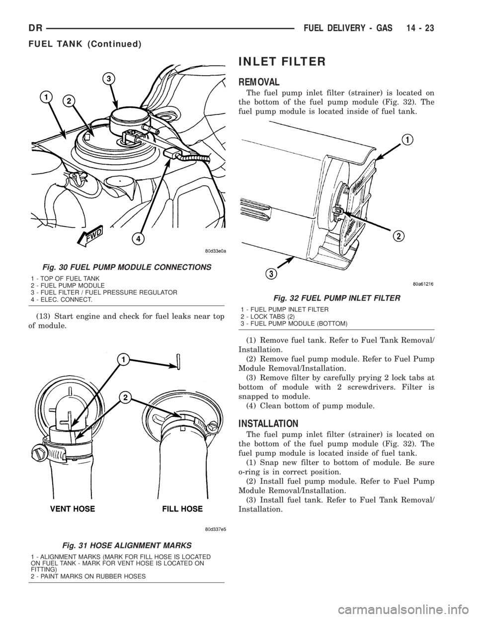
The fuel pump inlet filter (strainer) is located on
the bottom of the fuel pump module (Fig. 32). The
fuel pump module is located inside of fuel tank.
(1) Remove fuel tank. Refer to Fuel Tank Removal/
Installation.
(2) Remove fuel pump module. Refer to Fuel Pump
Module Removal/Installation.
(3) Remove filter by carefully prying 2 lock tabs at
bottom of module with 2 screwdrivers. Filter is
snapped to module.
(4) Clean bottom of pump module.
INSTALLATION
The fuel pump inlet filter (strainer) is located on
the bottom of the fuel pump module (Fig. 32). The
fuel pump module is located inside of fuel tank.
(1) Snap new filter to bottom of module. Be sure
o-ring is in correct position.
(2) Install fuel pump module. Refer to Fuel Pump
Module Removal/Installation.
(3) Install fuel tank. Refer to Fuel Tank Removal/
Installation.
Fig. 30 FUEL PUMP MODULE CONNECTIONS
1 - TOP OF FUEL TANK
2 - FUEL PUMP MODULE
3 - FUEL FILTER / FUEL PRESSURE REGULATOR
4 - ELEC. CONNECT.
Fig. 31 HOSE ALIGNMENT MARKS
1 - ALIGNMENT MARKS (MARK FOR FILL HOSE IS LOCATED
ON FUEL TANK - MARK FOR VENT HOSE IS LOCATED ON
FITTING)
2 - PAINT MARKS ON RUBBER HOSES
Fig. 32 FUEL PUMP INLET FILTER
1 - FUEL PUMP INLET FILTER
2 - LOCK TABS (2)
3 - FUEL PUMP MODULE (BOTTOM)
DRFUEL DELIVERY - GAS 14 - 23
FUEL TANK (Continued)
Page 1721 of 2895
FUEL INJECTION - GAS
TABLE OF CONTENTS
page page
ACCELERATOR PEDAL
REMOVAL.............................24
INSTALLATION.........................24
ACCELERATOR PEDAL POSITION SENSOR
DESCRIPTION.........................25
OPERATION...........................25
REMOVAL.............................25
INSTALLATION.........................25
CRANKSHAFT POSITION SENSOR
DESCRIPTION.........................26
OPERATION...........................26
REMOVAL.............................29
INSTALLATION.........................30
FUEL INJECTOR
DESCRIPTION.........................32
OPERATION
OPERATION - FUEL INJECTOR..........32
OPERATION - PCM OUTPUT............32
REMOVAL.............................32
INSTALLATION.........................33
FUEL PUMP RELAY
DESCRIPTION.........................33
OPERATION...........................33
REMOVAL.............................33
INSTALLATION.........................33
IDLE AIR CONTROL MOTOR
DESCRIPTION.........................33
OPERATION...........................33
REMOVAL.............................34INSTALLATION.........................35
INTAKE AIR TEMPERATURE SENSOR
DESCRIPTION.........................36
OPERATION...........................36
REMOVAL.............................36
INSTALLATION.........................38
MAP SENSOR
DESCRIPTION.........................39
OPERATION...........................39
REMOVAL.............................40
INSTALLATION.........................42
OXYGEN SENSOR
DESCRIPTION.........................43
OPERATION...........................43
REMOVAL.............................44
INSTALLATION.........................45
THROTTLE BODY
DESCRIPTION.........................45
OPERATION...........................45
REMOVAL.............................45
INSTALLATION.........................47
THROTTLE CONTROL CABLE
REMOVAL.............................49
INSTALLATION.........................51
THROTTLE POSITION SENSOR
DESCRIPTION.........................52
OPERATION...........................52
REMOVAL.............................53
INSTALLATION.........................54
ACCELERATOR PEDAL
REMOVAL
The following procedure applies only to vehicles
without the Adjustable Pedal Package (code XAP).
The accelerator pedal is serviced as a complete
assembly including the bracket.
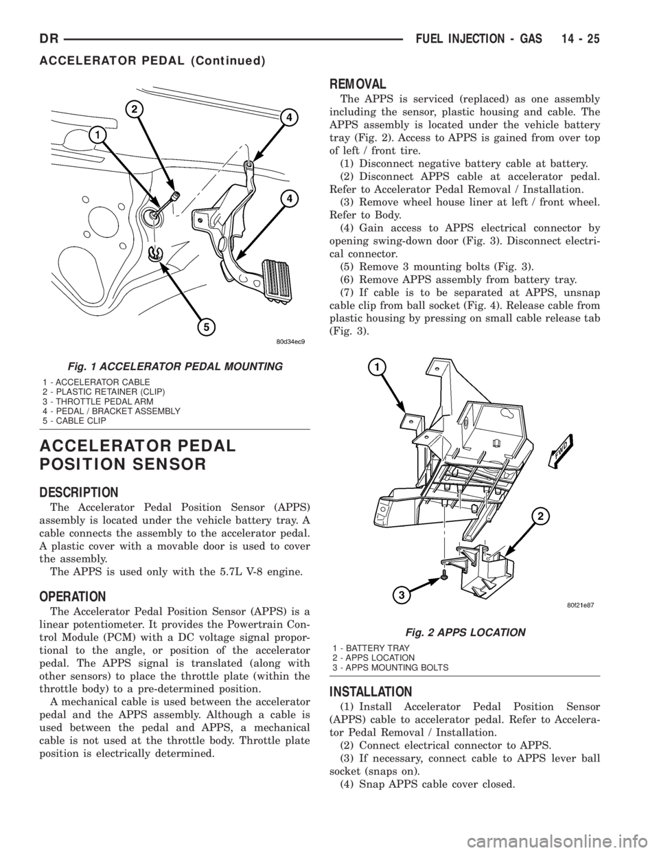
The accelerator cable is connected to the upper
part of the accelerator pedal arm by a plastic
retainer (clip) (Fig. 1). This plastic retainer snaps
into the top of the accelerator pedal arm.
(1) From inside the vehicle, hold up accelerator
pedal. Remove plastic cable retainer (clip) and throt-
tle cable core wire from upper end of accelerator
pedal arm (Fig. 1). Plastic cable retainer (clip) snaps
into pedal arm.(2) Remove 2 accelerator pedal mounting bracket
nuts. Remove accelerator pedal assembly.INSTALLATION
(1) Place accelerator pedal assembly over 2 studs.
(2) Install and tighten 2 mounting nuts. Refer to
Torque Specifications.
(3) Slide throttle cable into opening slot in top of
pedal arm.
(4) Push plastic cable retainer (clip) into accelera-
tor pedal arm opening until it snaps into place.
(5) Before starting engine, operate accelerator
pedal to check for any binding.
14 - 24 FUEL INJECTION - GASDR
Page 1722 of 2895
ACCELERATOR PEDAL
POSITION SENSOR
DESCRIPTION
The Accelerator Pedal Position Sensor (APPS)
assembly is located under the vehicle battery tray. A
cable connects the assembly to the accelerator pedal.
A plastic cover with a movable door is used to cover
the assembly.
The APPS is used only with the 5.7L V-8 engine.
OPERATION
The Accelerator Pedal Position Sensor (APPS) is a
linear potentiometer. It provides the Powertrain Con-
trol Module (PCM) with a DC voltage signal propor-
tional to the angle, or position of the accelerator
pedal. The APPS signal is translated (along with
other sensors) to place the throttle plate (within the
throttle body) to a pre-determined position.
A mechanical cable is used between the accelerator
pedal and the APPS assembly. Although a cable is
used between the pedal and APPS, a mechanical
cable is not used at the throttle body. Throttle plate
position is electrically determined.
REMOVAL
The APPS is serviced (replaced) as one assembly
including the sensor, plastic housing and cable. The
APPS assembly is located under the vehicle battery
tray (Fig. 2). Access to APPS is gained from over top
of left / front tire.
(1) Disconnect negative battery cable at battery.
(2) Disconnect APPS cable at accelerator pedal.
Refer to Accelerator Pedal Removal / Installation.
(3) Remove wheel house liner at left / front wheel.
Refer to Body.
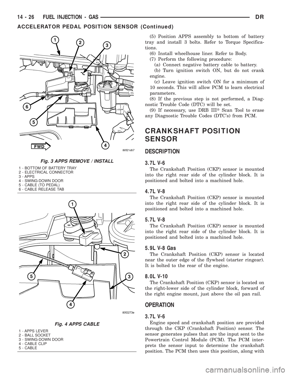
(4) Gain access to APPS electrical connector by
opening swing-down door (Fig. 3). Disconnect electri-
cal connector.
(5) Remove 3 mounting bolts (Fig. 3).
(6) Remove APPS assembly from battery tray.
(7) If cable is to be separated at APPS, unsnap
cable clip from ball socket (Fig. 4). Release cable from
plastic housing by pressing on small cable release tab
(Fig. 3).
INSTALLATION
(1) Install Accelerator Pedal Position Sensor
(APPS) cable to accelerator pedal. Refer to Accelera-
tor Pedal Removal / Installation.
(2) Connect electrical connector to APPS.
(3) If necessary, connect cable to APPS lever ball
socket (snaps on).
(4) Snap APPS cable cover closed.
Fig. 1 ACCELERATOR PEDAL MOUNTING
1 - ACCELERATOR CABLE
2 - PLASTIC RETAINER (CLIP)
3 - THROTTLE PEDAL ARM
4 - PEDAL / BRACKET ASSEMBLY
5 - CABLE CLIP
Fig. 2 APPS LOCATION
1 - BATTERY TRAY
2 - APPS LOCATION
3 - APPS MOUNTING BOLTS
DRFUEL INJECTION - GAS 14 - 25
ACCELERATOR PEDAL (Continued)
Page 1723 of 2895
(5) Position APPS assembly to bottom of battery
tray and install 3 bolts. Refer to Torque Specifica-
tions.
(6) Install wheelhouse liner. Refer to Body.
(7) Perform the following procedure:
(a) Connect negative battery cable to battery.
(b) Turn ignition switch ON, but do not crank
engine.
(c) Leave ignition switch ON for a minimum of
10 seconds. This will allow PCM to learn electrical
parameters.
(8) If the previous step is not performed, a Diag-
nostic Trouble Code (DTC) will be set.
(9) If necessary, use DRB IIItScan Tool to erase
any Diagnostic Trouble Codes (DTC's) from PCM.
CRANKSHAFT POSITION
SENSOR
DESCRIPTION
3.7L V-6
The Crankshaft Position (CKP) sensor is mounted
into the right rear side of the cylinder block. It is
positioned and bolted into a machined hole.
4.7L V-8
The Crankshaft Position (CKP) sensor is mounted
into the right rear side of the cylinder block. It is
positioned and bolted into a machined hole.
5.7L V-8
The Crankshaft Position (CKP) sensor is mounted
into the right rear side of the cylinder block. It is
positioned and bolted into a machined hole.
5.9L V-8 Gas
The Crankshaft Position (CKP) sensor is located
near the outer edge of the flywheel (starter ringear).
It is bolted to the rear of the engine.
8.0L V-10
The Crankshaft Position (CKP) sensor is located on
the right-lower side of the cylinder block, forward of
the right engine mount, just above the oil pan rail.
OPERATION
3.7L V-6
Engine speed and crankshaft position are provided
through the CKP (Crankshaft Position) sensor. The
sensor generates pulses that are the input sent to the
Powertrain Control Module (PCM). The PCM inter-
prets the sensor input to determine the crankshaft
position. The PCM then uses this position, along with
Fig. 3 APPS REMOVE / INSTALL
1 - BOTTOM OF BATTERY TRAY
2 - ELECTRICAL CONNECTOR
3 - APPS
4 - SWING-DOWN DOOR
5 - CABLE (TO PEDAL)
6 - CABLE RELEASE TAB
Fig. 4 APPS CABLE
1 - APPS LEVER
2 - BALL SOCKET
3 - SWING-DOWN DOOR
4 - CABLE CLIP
5 - CABLE
14 - 26 FUEL INJECTION - GASDR
ACCELERATOR PEDAL POSITION SENSOR (Continued)
Page 1724 of 2895
other inputs, to determine injector sequence and igni-
tion timing.
The sensor is a hall effect device combined with an
internal magnet. It is also sensitive to steel within a
certain distance from it.
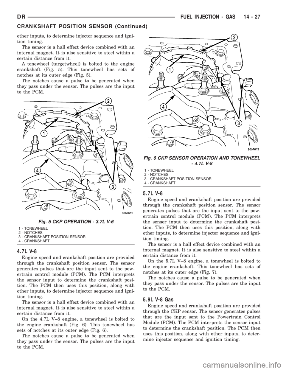
A tonewheel (targetwheel) is bolted to the engine
crankshaft (Fig. 5). This tonewheel has sets of
notches at its outer edge (Fig. 5).
The notches cause a pulse to be generated when
they pass under the sensor. The pulses are the input
to the PCM.
4.7L V-8
Engine speed and crankshaft position are provided
through the crankshaft position sensor. The sensor
generates pulses that are the input sent to the pow-
ertrain control module (PCM). The PCM interprets
the sensor input to determine the crankshaft posi-
tion. The PCM then uses this position, along with
other inputs, to determine injector sequence and igni-
tion timing.
The sensor is a hall effect device combined with an
internal magnet. It is also sensitive to steel within a
certain distance from it.
On the 4.7L V±8 engine, a tonewheel is bolted to
the engine crankshaft (Fig. 6). This tonewheel has
sets of notches at its outer edge (Fig. 6).
The notches cause a pulse to be generated when
they pass under the sensor. The pulses are the input
to the PCM.
5.7L V-8
Engine speed and crankshaft position are provided
through the crankshaft position sensor. The sensor
generates pulses that are the input sent to the pow-
ertrain control module (PCM). The PCM interprets
the sensor input to determine the crankshaft posi-
tion. The PCM then uses this position, along with
other inputs, to determine injector sequence and igni-
tion timing.
The sensor is a hall effect device combined with an
internal magnet. It is also sensitive to steel within a
certain distance from it.
On the 5.7L V±8 engine, a tonewheel is bolted to
the engine crankshaft. This tonewheel has sets of
notches at its outer edge (Fig. 7).
The notches cause a pulse to be generated when
they pass under the sensor. The pulses are the input
to the PCM.
5.9L V-8 Gas
Engine speed and crankshaft position are provided
through the CKP sensor. The sensor generates pulses
that are the input sent to the Powertrain Control
Module (PCM). The PCM interprets the sensor input
to determine the crankshaft position. The PCM then
uses this position, along with other inputs, to deter-
mine injector sequence and ignition timing.
Fig. 5 CKP OPERATION - 3.7L V-6
1 - TONEWHEEL
2 - NOTCHES
3 - CRANKSHAFT POSITION SENSOR
4 - CRANKSHAFT
Fig. 6 CKP SENSOR OPERATION AND TONEWHEEL
- 4.7L V-8
1 - TONEWHEEL
2 - NOTCHES
3 - CRANKSHAFT POSITION SENSOR
4 - CRANKSHAFT
DRFUEL INJECTION - GAS 14 - 27
CRANKSHAFT POSITION SENSOR (Continued)