2003 DODGE RAM engine
[x] Cancel search: enginePage 1745 of 2895
(6) Install control cables.
(7) Install electrical connectors.
(8) Install necessary vacuum lines.
(9) Install air plenum.
4.7L V-8
(1) Clean throttle body-to-intake manifold o-ring.
(2) Clean mating surfaces of throttle body and
intake manifold.
(3) Install throttle body to intake manifold by posi-
tioning throttle body to manifold alignment pins.
(4) Install three mounting bolts. Tighten bolts to
12 N´m (105 in. lbs.) torque.
(5) Install control cables.
(6) Install vacuum line to throttle body.
(7) Install electrical connectors.
(8) Install air plenum.
5.7L V-8
CAUTION: Do not use spray (carb) cleaners on any
part of the throttle body. Do not apply silicone lubri-
cants to any part of the throttle body.
(1) Clean and check condition of throttle body-to-
intake manifold o-ring.
(2) Clean mating surfaces of throttle body and
intake manifold.(3) Install throttle body to intake manifold by posi-
tioning throttle body to manifold alignment pins.
(4) Install 4 mounting bolts. Refer to Torque Spec-
ifications.
(5) Install electrical connector.
(6) Install air plenum.
(7)If the throttle body has been changed, the
following procedure must be performed:
(a) Disconnect negative battery cable from bat-
tery. Leave cable disconnected for approximately 90
seconds.
(b) Reconnect cable to battery.
(c) Turn ignition switch ON, but do not crank
engine.
(d) Leave ignition switch ON for a minimum of
10 seconds. This will allow PCM to learn throttle
body electrical parameters.
5.9L V-8
A (factory adjusted) set screw is used to mechani-
cally limit the position of the throttle body throttle
plate.Never attempt to adjust the engine idle
speed using this screw.All idle speed functions are
controlled by the powertrain control module (PCM).
(1) Clean the mating surfaces of the throttle body
and the intake manifold.
(2) Install new throttle body-to-intake manifold
gasket.
(3) Install throttle body to intake manifold.
(4) Install four mounting bolts. Tighten bolts to 23
N´m (200 in. lbs.) torque.
(5) Install control cables.
(6) Install vacuum line to throttle body.
(7) Install electrical connectors.
(8) Install air plenum.
8.0L V-10
A (factory adjusted) set screw is used to mechani-
cally limit the position of the throttle body throttle
plate.Never attempt to adjust the engine idle
speed using this screw.All idle speed functions are
controlled by the powertrain control module (PCM).
(1) Clean mating surfaces of throttle body and
intake manifold.
(2) Install new throttle body-to-intake manifold
gasket.
(3) Install throttle body to intake manifold.
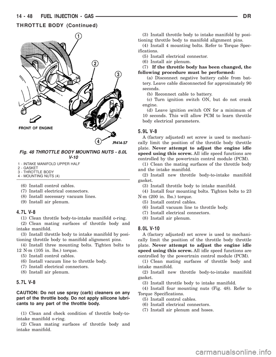
(4) Install four mounting nuts (Fig. 48). Refer to
Torque Specifications.
(5) Install control cables.
(6) Install electrical connectors.
(7) Install air plenum and hoses.
Fig. 48 THROTTLE BODY MOUNTING NUTS - 8.0L
V-10
1 - INTAKE MANIFOLD UPPER HALF
2 - GASKET
3 - THROTTLE BODY
4 - MOUNTING NUTS (4)
14 - 48 FUEL INJECTION - GASDR
THROTTLE BODY (Continued)
Page 1746 of 2895
THROTTLE CONTROL CABLE
REMOVAL
3.7L V-6
CAUTION: Be careful not to damage or kink cable
core wire (within cable sheathing) while servicing
accelerator pedal or throttle cable.
(1) From inside vehicle, hold up accelerator pedal.
Remove plastic cable retainer (clip) and throttle cable
core wire from upper end of pedal arm (Fig. 1). Plas-
tic cable retainer snaps into top of pedal arm.
(2) Remove cable core wire at pedal arm.
(3) From inside vehicle, remove metal clip holding
cable to dashpanel (Fig. 1).
(4) Remove air resonator box at throttle body.
(5) Unsnap cable from dashpanel routing clip.
(6) Remove cable housing from dash panel and
pull into engine compartment.
(7) Hold throttle in wide open position. While held
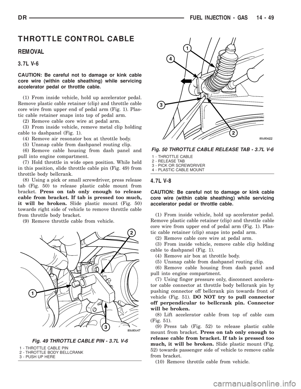
in this position, slide throttle cable pin (Fig. 49) from
throttle body bellcrank.
(8) Using a pick or small screwdriver, press release
tab (Fig. 50) to release plastic cable mount from
bracket.Press on tab only enough to release
cable from bracket. If tab is pressed too much,
it will be broken.Slide plastic mount (Fig. 50)
towards right side of vehicle to remove throttle cable
from throttle body bracket.
(9) Remove throttle cable from vehicle.
4.7L V-8
CAUTION: Be careful not to damage or kink cable
core wire (within cable sheathing) while servicing
accelerator pedal or throttle cable.
(1) From inside vehicle, hold up accelerator pedal.
Remove plastic cable retainer (clip) and throttle cable
core wire from upper end of pedal arm (Fig. 1). Plas-
tic cable retainer (clip) snaps into pedal arm.
(2) Remove cable core wire at pedal arm.
(3) From inside vehicle, remove cable clip holding
cable to dashpanel (Fig. 1).
(4) Remove air box at throttle body.
(5) Unsnap cable from dashpanel routing clip.
(6) Remove cable housing from dash panel and
pull into engine compartment.
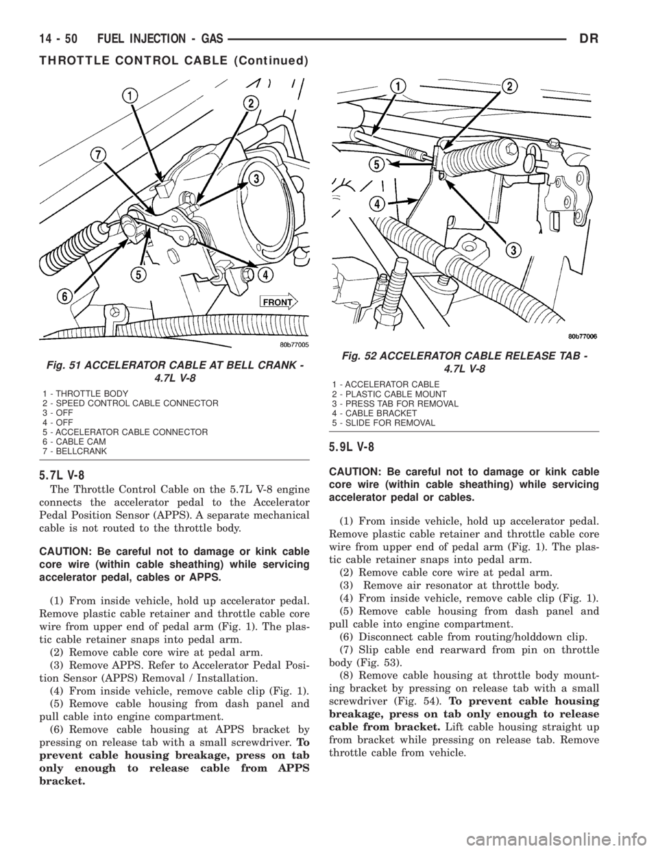
(7) Using finger pressure only, disconnect accelera-
tor cable connector at throttle body bellcrank pin by
pushing connector off bellcrank pin towards front of
vehicle (Fig. 51).DO NOT try to pull connector
off perpendicular to bellcrank pin. Connector
will be broken.
(8) Lift accelerator cable from top of cable cam
(Fig. 51).
(9) Press tab (Fig. 52) to release plastic cable
mount from bracket.Press on tab only enough to
release cable from bracket. If tab is pressed too
much, it will be broken.Slide plastic mount (Fig.
52) towards passenger side of vehicle to remove cable
from bracket.
(10) Remove throttle cable from vehicle.
Fig. 49 THROTTLE CABLE PIN - 3.7L V-6
1 - THROTTLE CABLE PIN
2 - THROTTLE BODY BELLCRANK
3 - PUSH UP HERE
Fig. 50 THROTTLE CABLE RELEASE TAB - 3.7L V-6
1 - THROTTLE CABLE
2 - RELEASE TAB
3 - PICK OR SCREWDRIVER
4 - PLASTIC CABLE MOUNT
DRFUEL INJECTION - GAS 14 - 49
Page 1747 of 2895
5.7L V-8
The Throttle Control Cable on the 5.7L V-8 engine
connects the accelerator pedal to the Accelerator
Pedal Position Sensor (APPS). A separate mechanical
cable is not routed to the throttle body.
CAUTION: Be careful not to damage or kink cable
core wire (within cable sheathing) while servicing
accelerator pedal, cables or APPS.
(1) From inside vehicle, hold up accelerator pedal.
Remove plastic cable retainer and throttle cable core
wire from upper end of pedal arm (Fig. 1). The plas-
tic cable retainer snaps into pedal arm.
(2) Remove cable core wire at pedal arm.
(3) Remove APPS. Refer to Accelerator Pedal Posi-
tion Sensor (APPS) Removal / Installation.
(4) From inside vehicle, remove cable clip (Fig. 1).
(5) Remove cable housing from dash panel and
pull cable into engine compartment.
(6) Remove cable housing at APPS bracket by
pressing on release tab with a small screwdriver.To
prevent cable housing breakage, press on tab
only enough to release cable from APPS
bracket.
5.9L V-8
CAUTION: Be careful not to damage or kink cable
core wire (within cable sheathing) while servicing
accelerator pedal or cables.
(1) From inside vehicle, hold up accelerator pedal.
Remove plastic cable retainer and throttle cable core
wire from upper end of pedal arm (Fig. 1). The plas-
tic cable retainer snaps into pedal arm.
(2) Remove cable core wire at pedal arm.
(3) Remove air resonator at throttle body.
(4) From inside vehicle, remove cable clip (Fig. 1).
(5) Remove cable housing from dash panel and
pull cable into engine compartment.
(6) Disconnect cable from routing/holddown clip.
(7) Slip cable end rearward from pin on throttle
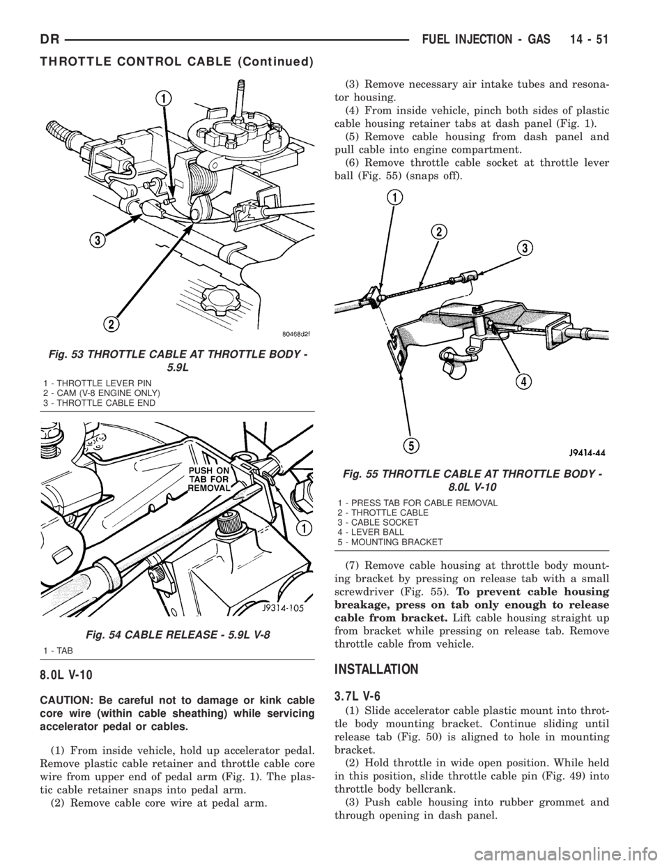
body (Fig. 53).
(8) Remove cable housing at throttle body mount-
ing bracket by pressing on release tab with a small
screwdriver (Fig. 54).To prevent cable housing
breakage, press on tab only enough to release
cable from bracket.Lift cable housing straight up
from bracket while pressing on release tab. Remove
throttle cable from vehicle.
Fig. 51 ACCELERATOR CABLE AT BELL CRANK -
4.7L V-8
1 - THROTTLE BODY
2 - SPEED CONTROL CABLE CONNECTOR
3 - OFF
4 - OFF
5 - ACCELERATOR CABLE CONNECTOR
6 - CABLE CAM
7 - BELLCRANK
Fig. 52 ACCELERATOR CABLE RELEASE TAB -
4.7L V-8
1 - ACCELERATOR CABLE
2 - PLASTIC CABLE MOUNT
3 - PRESS TAB FOR REMOVAL
4 - CABLE BRACKET
5 - SLIDE FOR REMOVAL
14 - 50 FUEL INJECTION - GASDR
THROTTLE CONTROL CABLE (Continued)
Page 1748 of 2895
8.0L V-10
CAUTION: Be careful not to damage or kink cable
core wire (within cable sheathing) while servicing
accelerator pedal or cables.
(1) From inside vehicle, hold up accelerator pedal.
Remove plastic cable retainer and throttle cable core
wire from upper end of pedal arm (Fig. 1). The plas-
tic cable retainer snaps into pedal arm.
(2) Remove cable core wire at pedal arm.(3) Remove necessary air intake tubes and resona-
tor housing.
(4) From inside vehicle, pinch both sides of plastic
cable housing retainer tabs at dash panel (Fig. 1).
(5) Remove cable housing from dash panel and
pull cable into engine compartment.
(6) Remove throttle cable socket at throttle lever
ball (Fig. 55) (snaps off).
(7) Remove cable housing at throttle body mount-
ing bracket by pressing on release tab with a small
screwdriver (Fig. 55).To prevent cable housing
breakage, press on tab only enough to release
cable from bracket.Lift cable housing straight up
from bracket while pressing on release tab. Remove
throttle cable from vehicle.
INSTALLATION
3.7L V-6
(1) Slide accelerator cable plastic mount into throt-
tle body mounting bracket. Continue sliding until
release tab (Fig. 50) is aligned to hole in mounting
bracket.
(2) Hold throttle in wide open position. While held
in this position, slide throttle cable pin (Fig. 49) into
throttle body bellcrank.
(3) Push cable housing into rubber grommet and
through opening in dash panel.
Fig. 53 THROTTLE CABLE AT THROTTLE BODY -
5.9L
1 - THROTTLE LEVER PIN
2 - CAM (V-8 ENGINE ONLY)
3 - THROTTLE CABLE END
Fig. 54 CABLE RELEASE - 5.9L V-8
1-TAB
Fig. 55 THROTTLE CABLE AT THROTTLE BODY -
8.0L V-10
1 - PRESS TAB FOR CABLE REMOVAL
2 - THROTTLE CABLE
3 - CABLE SOCKET
4 - LEVER BALL
5 - MOUNTING BRACKET
DRFUEL INJECTION - GAS 14 - 51
THROTTLE CONTROL CABLE (Continued)
Page 1749 of 2895
(4) From inside vehicle, install metal clip holding
cable to dashpanel (Fig. 1).
(5) From inside vehicle, slide throttle cable core
wire into opening (slot) in top of pedal arm.
(6) Push plastic cable retainer (clip) into pedal arm
opening until it snaps in place.
(7) Install air resonator tube to throttle body.
(8) Before starting engine, operate accelerator
pedal to check for any binding.
4.7L V-8
(1) Slide accelerator cable plastic mount into
bracket. Continue sliding until tab (Fig. 52) is
aligned to hole in mounting bracket.
(2) Route accelerator cable over top of cable cam.
(3) Connect cable end to throttle body bellcrank
pin (snaps on rearward).
(4) Slide rubber grommet away from plastic cable
housing.
(5) Install rubber grommet into dash panel until
seated.
(6) Push cable housing into rubber grommet and
through opening in dash panel.
(7) From inside vehicle, install clip holding cable
to dashpanel (Fig. 1).
(8) From inside vehicle, slide throttle cable core
wire into opening in top of pedal arm.
(9) Push cable retainer (clip) into pedal arm open-
ing until it snaps in place.
(10) Snap cable into dashpanel routing clip.
(11) Install air resonator tube to throttle body.
(12) Before starting engine, operate accelerator
pedal to check for any binding.
5.7L V-8
(1) Attach cable to Accelerator Pedal Position Sen-
sor (APPS). Refer to APPS Removal / Installation.
(2) Push cable housing into rubber grommet and
through opening in dash panel.
(3) From inside vehicle, install clip holding cable
to dashpanel (Fig. 1).
(4) From inside vehicle, slide throttle cable core
wire into opening in top of pedal arm.
(5) Push cable retainer (clip) into pedal arm open-
ing until it snaps in place.
(6) Before starting engine, operate accelerator
pedal to check for any binding.
(7) If necessary, use DRB IIItScan Tool to erase
any APPS Diagnostic Trouble Codes (DTC's) from
PCM.
5.9L V-8
(1) Slide accelerator cable plastic mount into throt-
tle body mounting bracket. Continue sliding until
release tab (Fig. 54) is aligned to hole in mounting
bracket.(2) Hold throttle in wide open position. While held
in this position, slide throttle cable pin into throttle
body bellcrank.
(3) Push cable housing into rubber grommet and
through opening in dash panel.
(4) From inside vehicle, install metal clip holding
cable to dashpanel (Fig. 1).
(5) From inside vehicle, slide throttle cable core
wire into opening (slot) in top of pedal arm.
(6) Push plastic cable retainer (clip) into pedal arm
opening until it snaps in place.
(7) Install air resonator tube to throttle body.
(8) Before starting engine, operate accelerator
pedal to check for any binding.
8.0L V-10
(1) Connect cable end socket to throttle body lever
ball (snaps on) (Fig. 55).
(2) Connect cable to throttle body mounting
bracket (push down and lock)
(3) Install the remaining cable housing end into
and through the dash panel opening (snaps into posi-
tion). The two plastic pinch tabs (Fig. 1) should lock
the cable to dash panel.
(4) From inside the vehicle, hold up the accelera-
tor pedal. Install the throttle cable core wire and
plastic cable retainer into and through the upper end
of the pedal arm (the plastic retainer is snapped into
the pedal arm). When installing the plastic retainer
to the accelerator pedal arm, note the index tab on
the pedal arm (Fig. 1). Align the index slot on the
plastic cable retainer to this index tab.
(5) Install air resonator tube to throttle body.
(6) Before starting engine, operate accelerator
pedal to check for any binding.
THROTTLE POSITION SENSOR
DESCRIPTION
The 3-wire Throttle Position Sensor (TPS) is
mounted on the throttle body and is connected to the
throttle blade shaft.
The 5.7L V-8 engine does not use a separate TPS
on the throttle body.
OPERATION
The 5.7L V-8 engine does not use a separate Throt-
tle Position Sensor (TPS) on the throttle body.
The 3±wire TPS provides the Powertrain Control
Module (PCM) with an input signal (voltage) that
represents the throttle blade position of the throttle
body. The sensor is connected to the throttle blade
shaft. As the position of the throttle blade changes,
the output voltage of the TPS changes.
14 - 52 FUEL INJECTION - GASDR
THROTTLE CONTROL CABLE (Continued)
Page 1750 of 2895
The PCM supplies approximately 5 volts to the
TPS. The TPS output voltage (input signal to the
PCM) represents the throttle blade position. The
PCM receives an input signal voltage from the TPS.
This will vary in an approximate range of from .26
volts at minimum throttle opening (idle), to 4.49 volts
at wide open throttle. Along with inputs from other
sensors, the PCM uses the TPS input to determine
current engine operating conditions. In response to
engine operating conditions, the PCM will adjust fuel
injector pulse width and ignition timing.
The PCM needs to identify the actions and position
of the throttle blade at all times. This information is
needed to assist in performing the following calcula-
tions:
²Ignition timing advance
²Fuel injection pulse-width
²Idle (learned value or minimum TPS)
²Off-idle (0.06 volt)
²Wide Open Throttle (WOT) open loop (2.608
volts above learned idle voltage)
²Deceleration fuel lean out
²Fuel cutoff during cranking at WOT (2.608 volts
above learned idle voltage)
²A/C WOT cutoff (certain automatic transmis-
sions only)
REMOVAL
3.7L V6
The Throttle Position Sensor (TPS) is mounted to
the throttle body (Fig. 56), or (Fig. 57).
(1) Remove air resonator tube at throttle body.
(2) Disconnect TPS electrical connector.
(3) Remove 2 TPS mounting screws.
(4) Remove TPS.
4.7L V-8
The TPS is located on the throttle body (Fig. 58).
(1) Remove air duct and tube at throttle body.
(2) Disconnect TPS electrical connector.
(3) Remove two TPS mounting bolts (screws) (Fig.
58).
(4) Remove TPS from throttle body.
5.7L V-8
The 5.7L V-8 engine does not use a separate Throt-
tle Position Sensor (TPS) on the throttle body.
5.9L V-8
The TPS is located on the side of the throttle body
(Fig. 59).
(1) Remove air intake tube at throttle body.
(2) Disconnect TPS electrical connector.
(3) Remove two TPS mounting bolts (Fig. 59).
(4) Remove TPS from throttle body.
8.0L V-10
The TPS is located on the side of the throttle body
(Fig. 60).
(1) Remove air plenum.
(2) Disconnect TPS electrical connector.
Fig. 56 TPS LOCATION - 3.7L V-6
1 - THROTTLE POSITION SENSOR (TPS)
2 - MOUNTING SCREWS
3 - IDLE AIR CONTROL MOTOR (IAC)
4 - MOUNTING SCREWS
Fig. 57 TPS INSTALLATION - 3.7 V-6
1 - THROTTLE BODY
2 - TPS
3 - THROTTLE BODY SHAFT
4 - SOCKET LOCATING TANGS
DRFUEL INJECTION - GAS 14 - 53
THROTTLE POSITION SENSOR (Continued)
Page 1751 of 2895
(3) Remove two TPS mounting bolts (Fig. 60).
(4) Remove TPS from throttle body.
INSTALLATION
3.7L V-6
The Throttle Position Sensor (TPS) is mounted to
the throttle body (Fig. 56).
The throttle shaft end of throttle body slides into a
socket in TPS (Fig. 61). The TPS must be installed so
that it can be rotated a few degrees. (If sensor will
not rotate, install sensor with throttle shaft on other
side of socket tangs). The TPS will be under slight
tension when rotated.
(1) Install TPS and retaining screws.
(2) Tighten screws to 7 N´m (60 in. lbs.) torque.
(3) Connect TPS electrical connector to TPS.
(4) Manually operate throttle (by hand) to check
for any TPS binding before starting engine.
(5) Install air cleaner tube to throttle body.
4.7L V-8
The throttle shaft end of throttle body slides into a
socket in TPS (Fig. 62). The TPS must be installed so
that it can be rotated a few degrees. If sensor will
not rotate, install sensor with throttle shaft on other
side of socket tangs. The TPS will be under slight
tension when rotated.
(1) Install TPS and two retaining bolts.
(2) Tighten bolts to 7 N´m (60 in. lbs.) torque.
(3) Manually operate throttle control lever by hand
to check for any binding of TPS.
(4) Connect TPS electrical connector to TPS.
Fig. 58 TPS LOCATION - 4.7L
1 - THROTTLE BODY
2 - TPS
3 - IAC MOTOR
4 - IAT SENSOR
5 - MOUNTING SCREWS
Fig. 59 TPS LOCATION - 5.9L V-8
1 - THROTTLE POSITION SENSOR
2 - MOUNTING SCREWS
Fig. 60 TPS MOUNTING BOLTS - 8.0L V-10
1 - MOUNTING BOLTS (2)
2 - IDLE AIR CONTROL MOTOR
3 - THROTTLE POSITION SENSOR
4 - THROTTLE BODY
14 - 54 FUEL INJECTION - GASDR
THROTTLE POSITION SENSOR (Continued)
Page 1754 of 2895
FUEL DELIVERY - DIESEL
DESCRIPTION - DIESEL FUEL SYSTEM
The fuel system used on the Cummins engine is an
electronically controlled, Bosch HPCR (High-Pressure
Common Rail) system. The HPCR system consists of
five main components:
²Electric Fuel Transfer (lift) Pump
²Fuel Pump/Gear Pump (attached to fuel injec-
tion pump)
²High-Pressure Fuel Injection Pump
²Fuel Injection Rail
²Fuel Injectors
Also to be considered as part of the overall fuel
system are:
²Accelerator Pedal
²Air Cleaner Housing/Element
²Fuel Drain Manifold (passage)
²Fuel Drain Valve (at filter)
²Fuel Filter/Water Separator
²Fuel Heater
²Fuel Heater Relay
²Fuel Level (gauge) Sending Unit
²Fuel Tank
²Fuel Tank Module (containing fuel gauge send-
ing unit and separate fuel filter located at bottom of
tank module)
²Fuel Tank Filler/Vent Tube Assembly
²Fuel Tank Filler Tube Cap
²Fuel Tubes/Lines/Hoses
²High-Pressure Fuel Injector Lines
²In-Tank Fuel Filter (at bottom of fuel tank mod-
ule)
²Low-Pressure Fuel Supply Lines
²Low-Pressure Fuel Return Line
²Overflow Valve
²Quick-Connect Fuel Line Fittings
²Throttle Cable
²Water Draining (maintenance)
²Water-In-Fuel (WIF) Sensor
The fuel injection pump supplies high pressure to
the fuel rail independent of engine speed. This high
pressure is then accumulated in the fuel rail. High
pressure fuel is constantly supplied to the injectors
by the fuel rail. The Engine Control Module (ECM)
controls the fueling and timing of the engine by actu-
ating the injectors.Fuel enters the system from the electric fuel trans-
fer (lift) pump, which is attached to the fuel filter
assembly. Fuel is forced through the fuel filter ele-
ment and then enters the Fuel Pump/Gear Pump,
which is attached to the rear of the fuel injection
pump. The Fuel Pump/Gear Pump is a low-pressure
pump and produce pressures ranging from 551.5 kpa
(80 psi) to 1241 kpa (180) psi. Fuel then enters the
fuel injection pump. Low pressure fuel is then sup-
plied to the FCA (Fuel Control Actuator).
The FCA is an electronically controlled solenoid
valve. The ECM controls the amount of fuel that
enters the high-pressure pumping chambers by open-
ing and closing the FCA based on a demanded fuel
pressure. The FPS (Fuel Pressure Sensor) on the fuel
rail provides the actual fuel pressure. When the
actuator is opened, the maximum amount of fuel is
being supplied to the fuel injection pump. Any fuel
that does not enter the injection pump is directed to
the overflow valve. The overflow valve regulates how
much excess fuel is used for lubrication of the pump
and how much is returned to the tank through the
drain manifold.
Fuel entering the injection pump is pressurized to
between 300 - 1600 bar by three radial pumping
chambers. The pressurized fuel is then supplied to
the fuel rail.
Some fuel system components are shown in.
WARNING: HIGH-PRESSURE FUEL LINES DELIVER
DIESEL FUEL UNDER EXTREME PRESSURE FROM
THE INJECTION PUMP TO THE FUEL INJECTORS.
THIS MAY BE AS HIGH AS 160,000 KPA (23,206
PSI). USE EXTREME CAUTION WHEN INSPECTING
FOR HIGH-PRESSURE FUEL LEAKS. INSPECT FOR
HIGH-PRESSURE FUEL LEAKS WITH A SHEET OF
CARDBOARD. HIGH FUEL INJECTION PRESSURE
CAN CAUSE PERSONAL INJURY IF CONTACT IS
MADE WITH THE SKIN.
Certain fuel system components can be found in
(Fig. 1), or (Fig. 2).
STANDARD PROCEDURE
STANDARD PROCEDURES - WATER DRAINING
AT FUEL FILTER
Refer to Fuel Filter/Water Separator removal/in-
stallation for procedures.
DRFUEL DELIVERY - DIESEL 14 - 57