2003 DODGE RAM warning
[x] Cancel search: warningPage 384 of 2895

²Cyclic Redundancy Check (CRC) Byte- This
byte is used to detect errors during a message trans-
mission.
²In-Frame Response (IFR) byte(s)-Ifa
response is required from the target module(s), it can
be sent during this frame. This function is described
in greater detail in the following paragraph.
The IFR consists of one or more bytes, which are
transmitted during a message. If the sending module
requires information to be received immediately, the
target module(s) can send data over the bus during
the original message. This allows the sending module
to receive time-critical information without having to
wait for the target module to access the bus. After
the IFR is received, the sending module broadcasts
an End of Frame (EOF) message and releases control
of the bus.
The PCI data bus can be monitored using the
DRBIIItscan tool. It is possible, however, for the bus
to pass all DRBIIIttests and still be faulty if the
voltage parameters are all within the specified range
and false messages are being sent.
CONTROLLER ANTILOCK
BRAKE
DESCRIPTION
The Controler Antilock Brake (CAB) is mounted to
the Hydraulic Control Unit (HCU) and operates the
ABS system (Fig. 1).
OPERATION
The CAB voltage source is through the ignition
switch in the RUN position. The CAB contains a self
check program that illuminates the ABS warning
light when a system fault is detected. Faults are
stored in a diagnostic program memory and are
accessible with the DRB III scan tool. ABS faults
remain in memory until cleared, or until after the
vehicle is started approximately 50 times. Stored
faults arenoterased if the battery is disconnected.
NOTE: If the CAB is being replaced with a new CAB
is must be reprogrammed with the use of a DRB III.
REMOVAL
(1) Remove the negative battery cable from the
battery.
(2) Pull up on the CAB harness connector release
and remove connector.
(3) Remove the CAB mounting bolts.
(4) Remove the pump connector from the CAB.
(5) Remove the CAB from the HCU.
INSTALLATION
NOTE: If the CAB is being replaced with a new CAB
is must be reprogrammed with the use of a DRB III.
(1) Install CAB to the HCU.
(2) Install the pump connector to the CAB.
(3) Install mounting bolts. Tighten to 2 N´m (16 in.
lbs.).
(4) Install the wiring harness connector to the
CAB and push down on the release to secure the con-
nector.
(5) Install negative battery cable to the battery.
DATA LINK CONNECTOR
DESCRIPTION - DATA LINK CONNECTOR
The Data Link Connector (DLC) is located at the
lower edge of the instrument panel near the steering
column.
OPERATION - DATA LINK CONNECTOR
The 16±way data link connector (diagnostic scan
tool connector) links the Diagnostic Readout Box
(DRB) scan tool or the Mopar Diagnostic System
(MDS) with the Powertrain Control Module (PCM).
Fig. 1 HYDRAULIC CONTROL UNIT
1 - HYDRAULIC CONTROL UNIT
2 - MOUNTING BOLTS
DRELECTRONIC CONTROL MODULES 8E - 3
COMMUNICATION (Continued)
Page 385 of 2895

ENGINE CONTROL MODULE
DESCRIPTION - ECM
The Engine Control Module (ECM) is bolted to the
left side of the engine below the intake manifold (Fig.
2).
OPERATION - ECM
The main function of the Engine Control Module
(ECM) is to electrically control the fuel system. The
Powertrain Control Module (PCM)does not control
the fuel system.
The ECM can adapt its programming to meet
changing operating conditions.If the ECM has
been replaced, flashed or re-calibrated, the
ECM must learn the Accelerator Pedal Position
Sensor (APPS) idle voltage. Failure to learn
this voltage may result in unnecessary diagnos-
tic trouble codes. Refer to ECM Removal/Instal-
lation for learning procedures.
The ECM receives input signals from various
switches and sensors. Based on these inputs, the
ECM regulates various engine and vehicle operations
through different system components. These compo-
nents are referred to asECM Outputs.The sensors
and switches that provide inputs to the ECM are
consideredECM Inputs.NOTE: ECM Inputs:
²Accelerator Pedal Position Sensor (APPS) Volts
²APPS1 Signal Ð For off engine APPS
²APPS2 Signal Ð For off engine APPS
²APPS Idle Validation Switches #1 and #2
²Battery voltage
²Camshaft Position Sensor (CMP)
²CCD bus (+) circuits
²CCD bus (-) circuits
²Crankshaft Position Sensor (CKP)
²Data link connection for DRB scan tool
²Engine Coolant Temperature (ECT) sensor
²Ground circuits
²Fuel Pressure Sensor
²Battery Temperature
²Fan speed
²Inlet Air Temperature Sensor/Pressure Sensor
²Intake Air Temperature Sensor/MAP Sensor
²Oil Pressure SWITCH
²Power ground
²Sensor return
²Signal ground
²Water-In-Fuel (WIF) sensor
NOTE: ECM Outputs:
After inputs are received by the ECM, certain sen-
sors, switches and components are controlled or reg-
ulated by the ECM. These are consideredECM
Outputs.These outputs are for:
²CCD bus (+) circuits
²CCD bus (-) circuits
²CKP and APPS outputs to the PCM
²Data link connection for DRB scan tool
²Five volt sensor supply
²Fuel transfer (lift) pump
²Intake manifold air heater relays #1 and #2 con-
trol circuits
²Malfunction indicator lamp (Check engine lamp)
(databus)
²Oil Pressure Swith/warning lamp (databus)
²Fuel Control Actuator
²Wait-to-start warning lamp (databus)
²Fan Clutch PWM
²Water-In-Fuel (WIF) warning lamp (databus)
REMOVAL
The Engine Control Module (ECM) is bolted to a
support bracket near the fuel filter. The support
bracket mounts to the block with four capscrews and
vibration isolators. A ground wire is fastened to the
bracket. The other end of the wire is fastened to the
engine block.
(1) Record any Diagnostic Trouble Codes (DTC's)
found in the ECM.
Fig. 2 DIESEL ECM
1 - ENGINE CONTROL MODULE (ECM)
2 - ECM MOUNTING BOLT
3 - 50-WAY CONNECTOR
4 - SUPPORT PLATE
5 - 60-WAY CONNECTOR
8E - 4 ELECTRONIC CONTROL MODULESDR
Page 413 of 2895

MICRO 420 BATTERY TESTER
The Micro 420 automotive battery tester is
designed to help the dealership technician diagnose
the cause of a defective battery. Follow the instruc-
tion manual supplied with the tester to properly
diagnose a battery. If the instruction manual is not
available, refer to the standard procedure in this sec-
tion, which includes the directions for using the
Micro 420 battery tester.
WARNING: IF THE BATTERY SHOWS SIGNS OF
FREEZING, LEAKING OR LOOSE POSTS, DO NOT
TEST, ASSIST-BOOST, OR CHARGE. THE BATTERY
MAY ARC INTERNALLY AND EXPLODE. PERSONAL
INJURY AND/OR VEHICLE DAMAGE MAY RESULT.
WARNING: EXPLOSIVE HYDROGEN GAS FORMS IN
AND AROUND THE BATTERY. DO NOT SMOKE,
USE FLAME, OR CREATE SPARKS NEAR THE BAT-
TERY. PERSONAL INJURY AND/OR VEHICLE DAM-
AGE MAY RESULT.
WARNING: THE BATTERY CONTAINS SULFURIC
ACID, WHICH IS POISONOUS AND CAUSTIC. AVOID
CONTACT WITH THE SKIN, EYES, OR CLOTHING.
IN THE EVENT OF CONTACT, FLUSH WITH WATER
AND CALL A PHYSICIAN IMMEDIATELY. KEEP OUT
OF THE REACH OF CHILDREN.
A battery that will not accept a charge is faulty,
and must be replaced. Further testing is not
required. A fully-charged battery must be load tested
to determine its cranking capacity. A battery that is
fully-charged, but does not pass the load test, is
faulty and must be replaced. Always test battery
using the Micro 420 battery tester before attempting
to replace a battery under the manufactures war-
ranty provisions.
NOTE: Completely discharged batteries may take
several hours to accept a charge. Refer to Standard
Procedures for the proper battery charging proce-
dures.
STANDARD PROCEDURE
STANDARD PROCEDURE - BATTERY
CHARGING
Battery charging can be performed fast or slow, in
terms of time.Slowbattery charging is the best
means of restoring a battery to full potential. Fast
battery charging should only be performed whenabsolutely necessary due to time restraints. A battery
is fully-charged when:
²All of the battery cells are gassing freely during
battery charging.
²A green color is visible in the sight glass of the
battery built-in test indicator.
²Three hydrometer tests, taken at one-hour inter-
vals, indicate no increase in the temperature-cor-
rected specific gravity of the battery electrolyte.
²Open-circuit voltage of the battery is 12.65 volts
or above.
WARNING: NEVER EXCEED TWENTY AMPERES
WHEN CHARGING A COLD (-1É C [30É F] OR
LOWER) BATTERY. THE BATTERY MAY ARC INTER-
NALLY AND EXPLODE. PERSONAL INJURY AND/OR
VEHICLE DAMAGE MAY RESULT.
CAUTION: Always disconnect and isolate the bat-
tery negative cable before charging a battery. Do
not exceed sixteen volts while charging a battery.
Damage to the vehicle electrical system compo-
nents may result.
CAUTION: Battery electrolyte will bubble inside the
battery case during normal battery charging. Elec-
trolyte boiling or being discharged from the battery
vents indicates a battery overcharging condition.
Immediately reduce the charging rate or turn off the
charger to evaluate the battery condition. Damage
to the battery may result from overcharging.
CAUTION: The battery should not be hot to the
touch. If the battery feels hot to the touch, turn off
the charger and let the battery cool before continu-
ing the charging operation. Damage to the battery
may result.
NOTE: Models equipped with the diesel engine are
equipped with two 12-volt batteries, connected in
parallel (positive-to-positive and negative-to-nega-
tive). In order to ensure proper charging of each
battery, these batteries MUST be disconnected from
each other, as well as from the vehicle electrical
system while being charged.
Some battery chargers are equipped with polarity-
sensing circuitry. This circuitry protects the battery
charger and the battery from being damaged if they
are improperly connected. If the battery state-of-
charge is too low for the polarity-sensing circuitry to
detect, the battery charger will not operate. This
makes it appear that the battery will not accept
charging current. See the instructions provided by
8F - 8 BATTERY SYSTEMDR
BATTERY (Continued)
Page 418 of 2895
WARNING: ALWAYS WEAR APPROPRIATE EYE
PROTECTION AND USE EXTREME CAUTION WHEN
WORKING WITH BATTERIES.
BATTERY TESTING
(1) If testing the battery OUT-OF-VEHICLE, clean
the battery terminals with a wire brush before test-
ing. If the battery is equipped with side post termi-
nals, install and tighten the supplied lead terminal
stud adapters. Do not use steel bolts. Failure to prop-
erly install the stud adapters, or using stud adapters
that are dirty or worn-out may result in false test
readings.
(2) If testing the battery IN-THE-VEHICLE, make
certain all of the vehicle accessory loads are OFF,
including the ignition.The preferred test position
is at the battery terminal. If the battery is not
accessible, you may test using both the positive and
negative jumper posts. Select TESTING AT JUMPER
POST when connecting to that location.
(3) Connect the tester (Fig. 9) to the battery or
jumper posts, the red clamp to positive (+) and the
black clamp to negative (±).
NOTE: Multiple batteries connected in parallel must
have the ground cable disconnected to perform a
battery test. Failure to disconnect may result in
false battery test readings.
(4) Using the ARROW key selectinoroutof vehi-
cle testing and press ENTER to make a selection.
(5) If not selected, choose the Cold Cranking Amp
(CCA) battery rating. Or select the appropriate bat-
tery rating for your area (see menu). The tester will
then run its self programmed test of the battery and
display the results. Refer to the test result table
noted below.
CAUTION: If REPLACE BATTERY is the result of the
test, this may mean a poor connection between the
vehicle's cables and battery exists. After discon-
necting the vehicle's battery cables from the bat-
tery, retest the battery using the OUT-OF-VEHICLE
test before replacing.
(6) While viewing the battery test result, press the
CODE button and the tester will prompt you for the
last 4 digits of the VIN. Use the UP/DOWN arrow
buttons to scroll to the correct character; then press
ENTER to select and move to the next digit. Then
press the ENTER button to view the SERVICE
CODE. Pressing the CODE button a second time will
return you to the test results.
BATTERY TEST RESULTS
GOOD BATTERY Return to service
GOOD - RECHARGE Fully charge battery and
return to service
CHARGE & RETEST Fully charge battery and
retest battery
REPLACE BATTERY Replace the battery and
retest complete system
BAD-CELL REPLACE Replace the battery and
retest complete system
NOTE: The SERVICE CODE is required on every
warranty claim submitted for battery replacement.
REMOVAL
(1) Turn the ignition switch to the Off position. Be
certain that all electrical accessories are turned off.
(2) Loosen the battery negative cable terminal
clamp pinch-bolt hex nut.
(3) Disconnect the battery negative cable terminal
clamp from the battery negative terminal post. If
necessary, use a battery terminal puller to remove
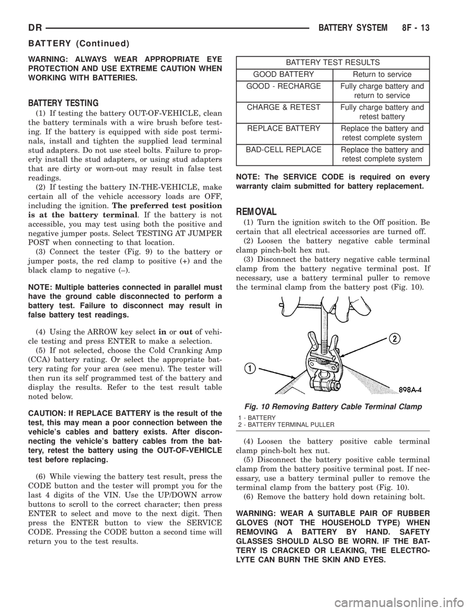
the terminal clamp from the battery post (Fig. 10).
(4) Loosen the battery positive cable terminal
clamp pinch-bolt hex nut.
(5) Disconnect the battery positive cable terminal
clamp from the battery positive terminal post. If nec-
essary, use a battery terminal puller to remove the
terminal clamp from the battery post (Fig. 10).
(6) Remove the battery hold down retaining bolt.
WARNING: WEAR A SUITABLE PAIR OF RUBBER
GLOVES (NOT THE HOUSEHOLD TYPE) WHEN
REMOVING A BATTERY BY HAND. SAFETY
GLASSES SHOULD ALSO BE WORN. IF THE BAT-
TERY IS CRACKED OR LEAKING, THE ELECTRO-
LYTE CAN BURN THE SKIN AND EYES.
Fig. 10 Removing Battery Cable Terminal Clamp
1 - BATTERY
2 - BATTERY TERMINAL PULLER
DRBATTERY SYSTEM 8F - 13
BATTERY (Continued)
Page 420 of 2895
also provide a return path for electrical current gen-
erated by the charging system for restoring the volt-
age potential of the battery. The female battery
terminal clamps on the ends of the battery cable
wires provide a strong and reliable connection of the
battery cable to the battery terminal posts. The ter-
minal pinch bolts allow the female terminal clamps
to be tightened around the male terminal posts on
the top of the battery. The eyelet terminals secured
to the ends of the battery cable wires opposite the
female battery terminal clamps provide secure and
reliable connection of the battery to the vehicle elec-
trical system.
DIAGNOSIS AND TESTING - BATTERY CABLES
A voltage drop test will determine if there is exces-
sive resistance in the battery cable terminal connec-
tions or the battery cables. If excessive resistance is
found in the battery cable connections, the connec-
tion point should be disassembled, cleaned of all cor-
rosion or foreign material, then reassembled.
Following reassembly, check the voltage drop for the
battery cable connection and the battery cable again
to confirm repair.
When performing the voltage drop test, it is impor-
tant to remember that the voltage drop is giving an
indication of the resistance between the two points at
which the voltmeter probes are attached.EXAM-
PLE:When testing the resistance of the battery pos-
itive cable, touch the voltmeter leads to the battery
positive cable terminal clamp and to the battery pos-
itive cable eyelet terminal at the starter solenoid
B(+) terminal stud. If you probe the battery positive
terminal post and the battery positive cable eyelet
terminal at the starter solenoid B(+) terminal stud,
you are reading the combined voltage drop in the
battery positive cable terminal clamp-to-terminal
post connection and the battery positive cable.
VOLTAGE DROP TEST
WARNING: MODELS EQUIPPED WITH A DIESEL
ENGINE HAVE AN AUTOMATIC SHUTDOWN (ASD)
RELAY LOCATED IN THE POWER DISTRIBUTION
CENTER (PDC). REMOVAL OF THE ASD RELAY
MAY NOT PREVENT THE DIESEL ENGINE FROM
STARTING. BE CERTAIN TO DISCONNECT THE
FUEL SHUTDOWN SOLENOID WIRE HARNESS
CONNECTOR TO PREVENT THE ENGINE FROM
STARTING. FAILURE TO DO SO MAY RESULT IN
PERSONAL INJURY.
The following operation will require a voltmeter
accurate to 1/10 (0.10) volt. Before performing this
test, be certain that the following procedures are
accomplished:²The battery is fully-charged and tested (Refer to
8 - ELECTRICAL/BATTERY SYSTEM/BATTERY -
STANDARD PROCEDURE).
²Fully engage the parking brake.
²If the vehicle is equipped with an automatic
transmission, place the gearshift selector lever in the
Park position. If the vehicle is equipped with a man-
ual transmission, place the gearshift selector lever in
the Neutral position and block the clutch pedal in the
fully depressed position.
²Verify that all lamps and accessories are turned
off.
²To prevent a gasoline engine from starting,
remove the Automatic ShutDown (ASD) relay. The
ASD relay is located in the Integrated Power Module
(IPM), in the engine compartment. See the fuse and
relay layout label on the underside of the IPM cover
for ASD relay identification and location.
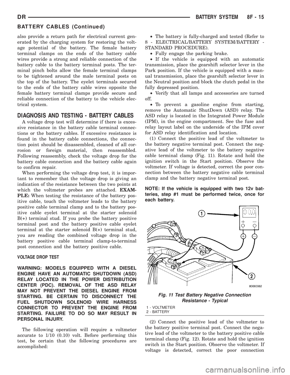
(1) Connect the positive lead of the voltmeter to
the battery negative terminal post. Connect the neg-
ative lead of the voltmeter to the battery negative
cable terminal clamp (Fig. 11). Rotate and hold the
ignition switch in the Start position. Observe the
voltmeter. If voltage is detected, correct the poor con-
nection between the battery negative cable terminal
clamp and the battery negative terminal post.
NOTE: If the vehicle is equipped with two 12v bat-
teries, step #1 must be performed twice, once for
each battery.
(2) Connect the positive lead of the voltmeter to
the battery positive terminal post. Connect the nega-
tive lead of the voltmeter to the battery positive cable
terminal clamp (Fig. 12). Rotate and hold the ignition
switch in the Start position. Observe the voltmeter. If
voltage is detected, correct the poor connection
Fig. 11 Test Battery Negative Connection
Resistance - Typical
1 - VOLTMETER
2 - BATTERY
DRBATTERY SYSTEM 8F - 15
BATTERY CABLES (Continued)
Page 427 of 2895
GENERATOR
DESCRIPTION
The generator is belt-driven by the engine using a
serpentine type drive belt. It is serviced only as a
complete assembly. If the generator fails for any rea-
son, the entire assembly must be replaced.
OPERATION
As the energized rotor begins to rotate within the
generator, the spinning magnetic field induces a cur-
rent into the windings of the stator coil. Once the
generator begins producing sufficient current, it also
provides the current needed to energize the rotor.
The stator winding connections deliver the induced
alternating current to 3 positive and 3 negative
diodes for rectification. From the diodes, rectified
direct current is delivered to the vehicle electrical
system through the generator battery terminal.
Although the generators appear the same exter-
nally, different generators with different output rat-
ings are used on this vehicle. Be certain that the
replacement generator has the same output rating
and part number as the original unit. Refer to Gen-
erator Ratings in the Specifications section at the
back of this group for amperage ratings and part
numbers.
Noise emitting from the generator may be caused
by: worn, loose or defective bearings; a loose or defec-
tive drive pulley; incorrect, worn, damaged or misad-
justed fan drive belt; loose mounting bolts; a
misaligned drive pulley or a defective stator or diode.
REMOVAL
3.7L / 4.7L
WARNING: DISCONNECT NEGATIVE CABLE FROM
BATTERY BEFORE REMOVING BATTERY OUTPUT
WIRE (B+ WIRE) FROM GENERATOR. FAILURE TO
DO SO CAN RESULT IN INJURY OR DAMAGE TO
ELECTRICAL SYSTEM.
(1) Disconnect negative battery cable at battery.
(2) Remove generator drive belt. Refer to 7, Cool-
ing System for procedure.
(3) Unsnap plastic insulator cap from B+ output
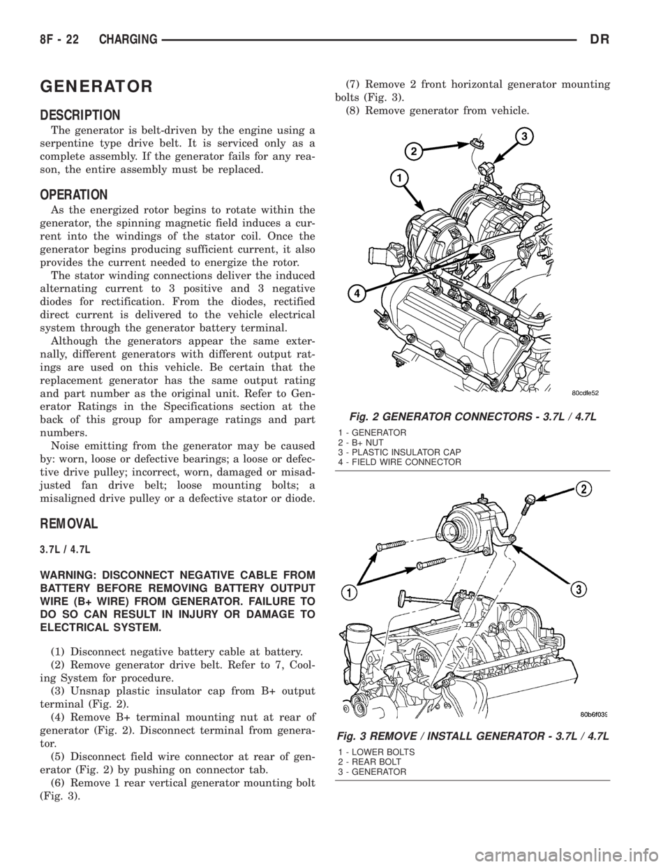
terminal (Fig. 2).
(4) Remove B+ terminal mounting nut at rear of
generator (Fig. 2). Disconnect terminal from genera-
tor.
(5) Disconnect field wire connector at rear of gen-
erator (Fig. 2) by pushing on connector tab.
(6) Remove 1 rear vertical generator mounting bolt
(Fig. 3).(7) Remove 2 front horizontal generator mounting
bolts (Fig. 3).
(8) Remove generator from vehicle.
Fig. 2 GENERATOR CONNECTORS - 3.7L / 4.7L
1 - GENERATOR
2-B+NUT
3 - PLASTIC INSULATOR CAP
4 - FIELD WIRE CONNECTOR
Fig. 3 REMOVE / INSTALL GENERATOR - 3.7L / 4.7L
1 - LOWER BOLTS
2 - REAR BOLT
3 - GENERATOR
8F - 22 CHARGINGDR
Page 428 of 2895
5.7L
WARNING: DISCONNECT NEGATIVE CABLE FROM
BATTERY BEFORE REMOVING BATTERY OUTPUT
WIRE (B+ WIRE) FROM GENERATOR. FAILURE TO
DO SO CAN RESULT IN INJURY OR DAMAGE TO
ELECTRICAL SYSTEM.
(1) Disconnect negative battery cable at battery.
(2) Remove generator drive belt. Refer to 7, Cool-
ing System for procedure.
(3) Unsnap plastic insulator cap from B+ output
terminal.
(4) Remove B+ terminal mounting nut at rear of
generator. Disconnect terminal from generator.
(5) Disconnect field wire connector at rear of gen-
erator by pushing on connector tab.
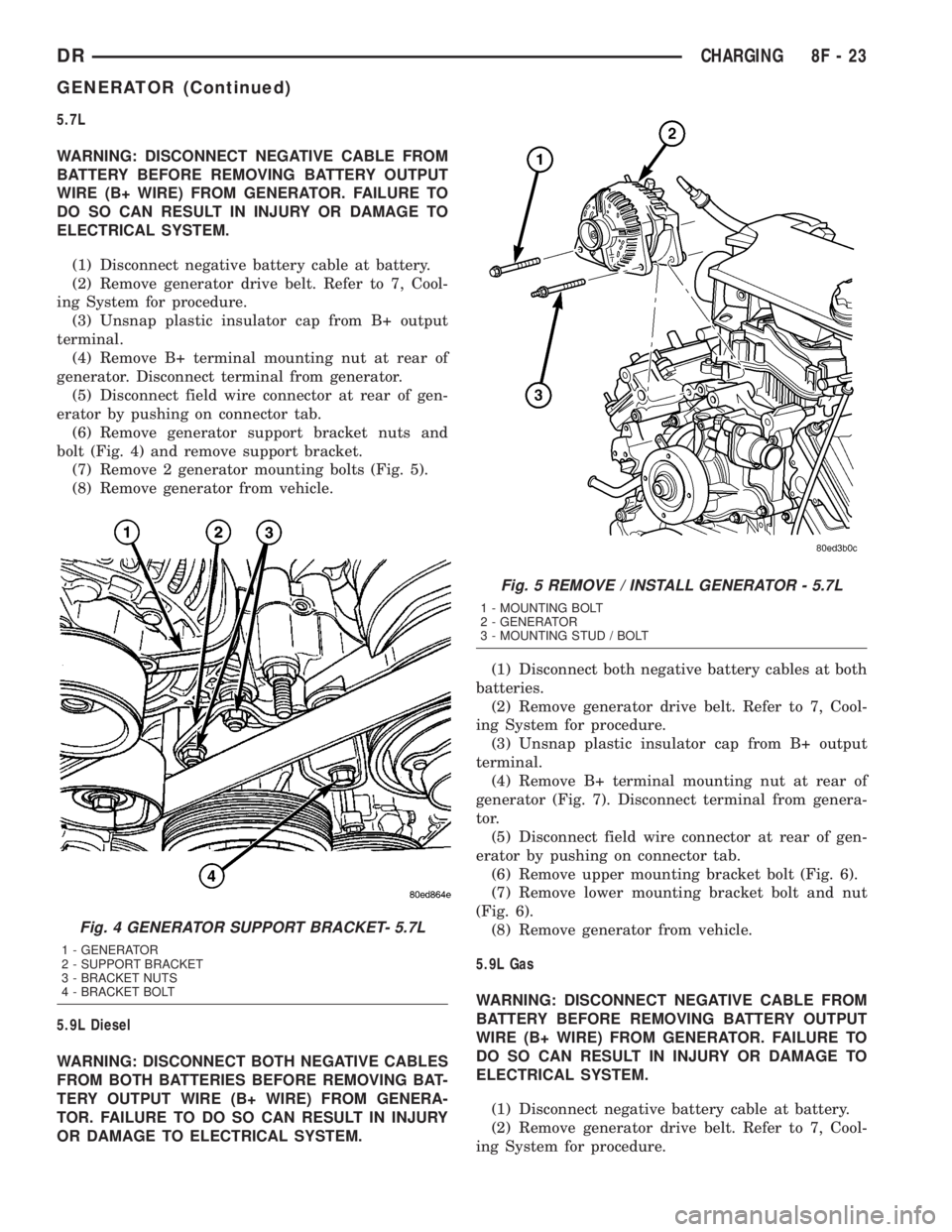
(6) Remove generator support bracket nuts and
bolt (Fig. 4) and remove support bracket.
(7) Remove 2 generator mounting bolts (Fig. 5).
(8) Remove generator from vehicle.
5.9L Diesel
WARNING: DISCONNECT BOTH NEGATIVE CABLES
FROM BOTH BATTERIES BEFORE REMOVING BAT-
TERY OUTPUT WIRE (B+ WIRE) FROM GENERA-
TOR. FAILURE TO DO SO CAN RESULT IN INJURY
OR DAMAGE TO ELECTRICAL SYSTEM.(1) Disconnect both negative battery cables at both
batteries.
(2) Remove generator drive belt. Refer to 7, Cool-
ing System for procedure.
(3) Unsnap plastic insulator cap from B+ output
terminal.
(4) Remove B+ terminal mounting nut at rear of
generator (Fig. 7). Disconnect terminal from genera-
tor.
(5) Disconnect field wire connector at rear of gen-
erator by pushing on connector tab.
(6) Remove upper mounting bracket bolt (Fig. 6).
(7) Remove lower mounting bracket bolt and nut
(Fig. 6).
(8) Remove generator from vehicle.
5.9L Gas
WARNING: DISCONNECT NEGATIVE CABLE FROM
BATTERY BEFORE REMOVING BATTERY OUTPUT
WIRE (B+ WIRE) FROM GENERATOR. FAILURE TO
DO SO CAN RESULT IN INJURY OR DAMAGE TO
ELECTRICAL SYSTEM.
(1) Disconnect negative battery cable at battery.
(2) Remove generator drive belt. Refer to 7, Cool-
ing System for procedure.
Fig. 4 GENERATOR SUPPORT BRACKET- 5.7L
1 - GENERATOR
2 - SUPPORT BRACKET
3 - BRACKET NUTS
4 - BRACKET BOLT
Fig. 5 REMOVE / INSTALL GENERATOR - 5.7L
1 - MOUNTING BOLT
2 - GENERATOR
3 - MOUNTING STUD / BOLT
DRCHARGING 8F - 23
GENERATOR (Continued)
Page 429 of 2895
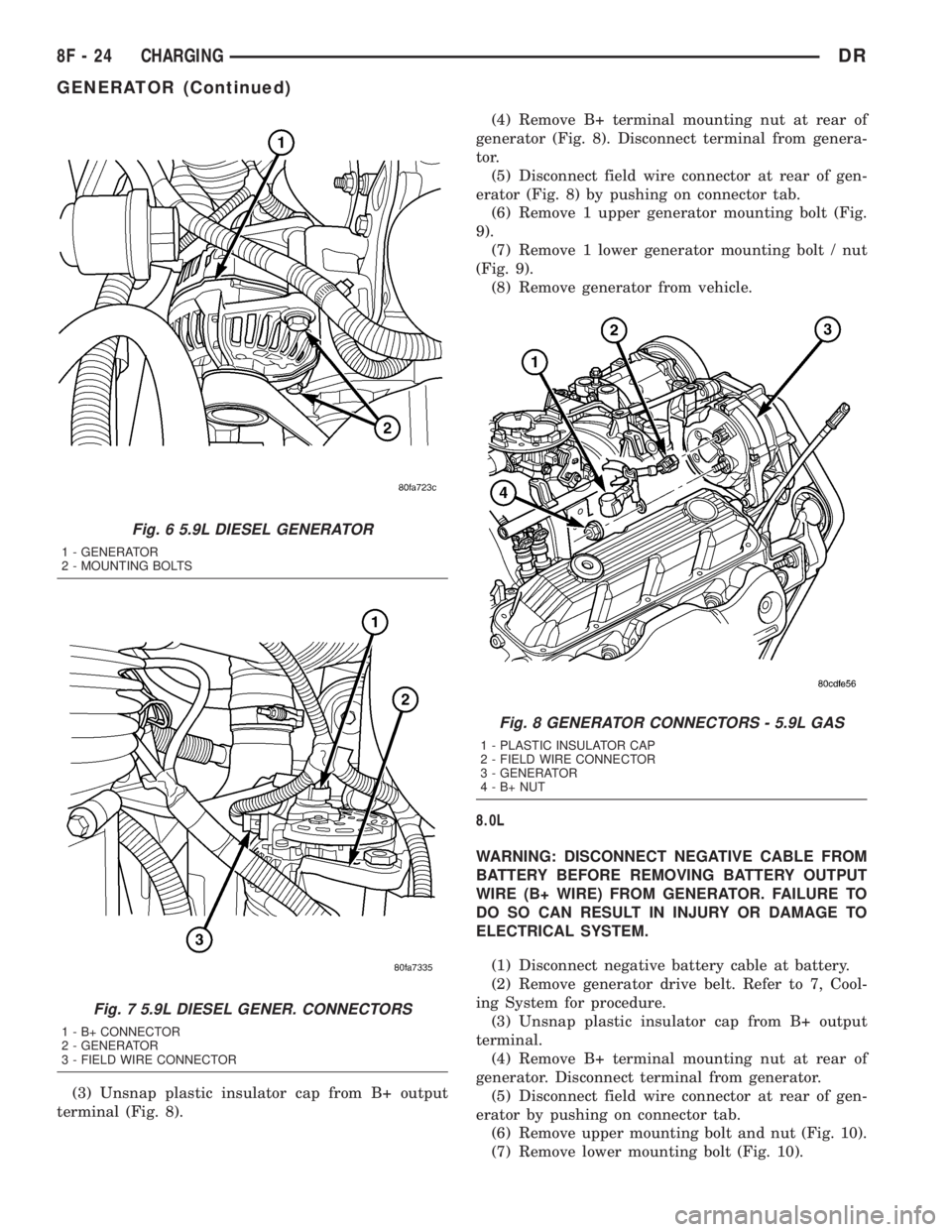
(3) Unsnap plastic insulator cap from B+ output
terminal (Fig. 8).(4) Remove B+ terminal mounting nut at rear of
generator (Fig. 8). Disconnect terminal from genera-
tor.
(5) Disconnect field wire connector at rear of gen-
erator (Fig. 8) by pushing on connector tab.
(6) Remove 1 upper generator mounting bolt (Fig.
9).
(7) Remove 1 lower generator mounting bolt / nut
(Fig. 9).
(8) Remove generator from vehicle.
8.0L
WARNING: DISCONNECT NEGATIVE CABLE FROM
BATTERY BEFORE REMOVING BATTERY OUTPUT
WIRE (B+ WIRE) FROM GENERATOR. FAILURE TO
DO SO CAN RESULT IN INJURY OR DAMAGE TO
ELECTRICAL SYSTEM.
(1) Disconnect negative battery cable at battery.
(2) Remove generator drive belt. Refer to 7, Cool-
ing System for procedure.
(3) Unsnap plastic insulator cap from B+ output
terminal.
(4) Remove B+ terminal mounting nut at rear of
generator. Disconnect terminal from generator.
(5) Disconnect field wire connector at rear of gen-
erator by pushing on connector tab.
(6) Remove upper mounting bolt and nut (Fig. 10).
(7) Remove lower mounting bolt (Fig. 10).
Fig. 6 5.9L DIESEL GENERATOR
1 - GENERATOR
2 - MOUNTING BOLTS
Fig. 7 5.9L DIESEL GENER. CONNECTORS
1 - B+ CONNECTOR
2 - GENERATOR
3 - FIELD WIRE CONNECTOR
Fig. 8 GENERATOR CONNECTORS - 5.9L GAS
1 - PLASTIC INSULATOR CAP
2 - FIELD WIRE CONNECTOR
3 - GENERATOR
4-B+NUT
8F - 24 CHARGINGDR
GENERATOR (Continued)