2003 DODGE RAM warning
[x] Cancel search: warningPage 435 of 2895
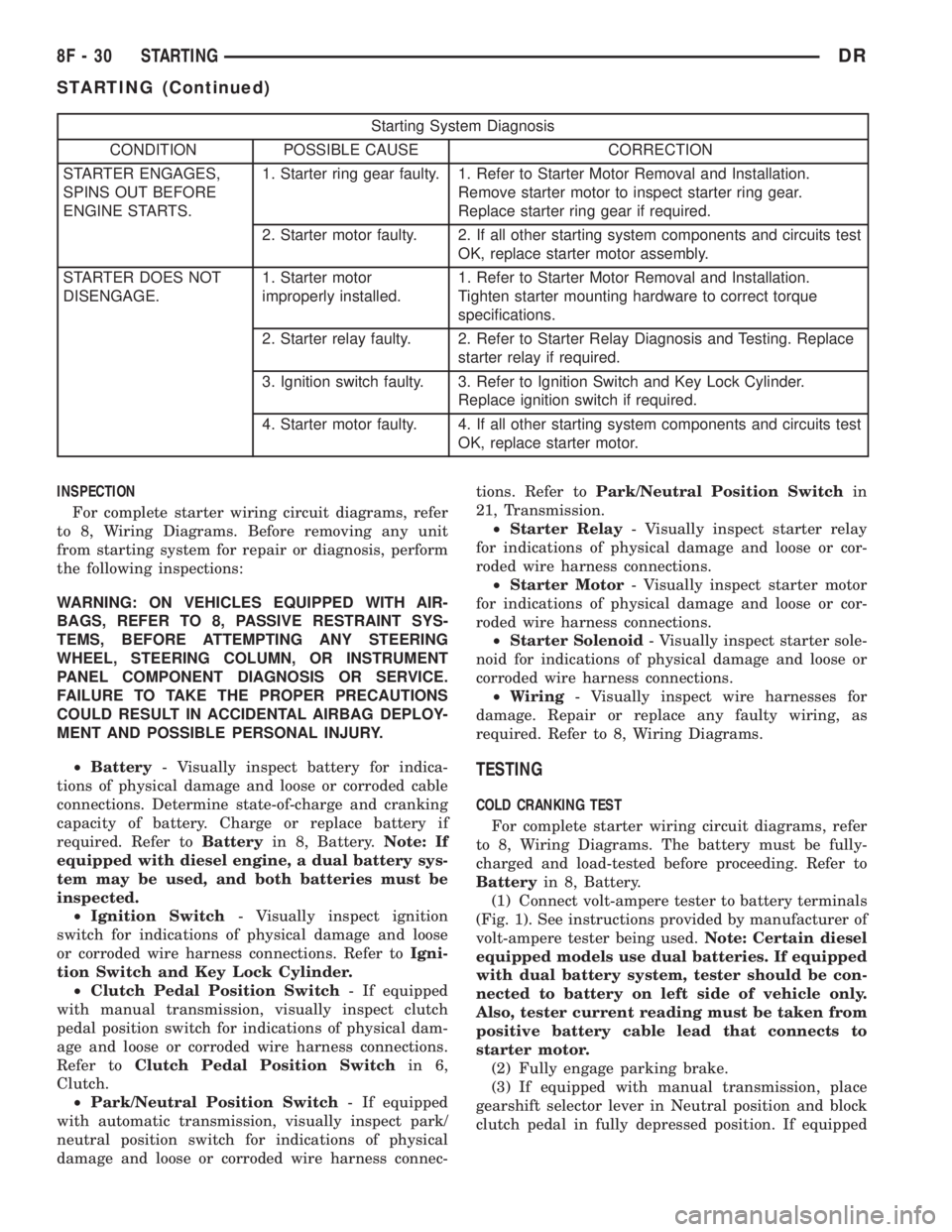
Starting System Diagnosis
CONDITION POSSIBLE CAUSE CORRECTION
STARTER ENGAGES,
SPINS OUT BEFORE
ENGINE STARTS.1. Starter ring gear faulty. 1. Refer to Starter Motor Removal and Installation.
Remove starter motor to inspect starter ring gear.
Replace starter ring gear if required.
2. Starter motor faulty. 2. If all other starting system components and circuits test
OK, replace starter motor assembly.
STARTER DOES NOT
DISENGAGE.1. Starter motor
improperly installed.1. Refer to Starter Motor Removal and Installation.
Tighten starter mounting hardware to correct torque
specifications.
2. Starter relay faulty. 2. Refer to Starter Relay Diagnosis and Testing. Replace
starter relay if required.
3. Ignition switch faulty. 3. Refer to Ignition Switch and Key Lock Cylinder.
Replace ignition switch if required.
4. Starter motor faulty. 4. If all other starting system components and circuits test
OK, replace starter motor.
INSPECTION
For complete starter wiring circuit diagrams, refer
to 8, Wiring Diagrams. Before removing any unit
from starting system for repair or diagnosis, perform
the following inspections:
WARNING: ON VEHICLES EQUIPPED WITH AIR-
BAGS, REFER TO 8, PASSIVE RESTRAINT SYS-
TEMS, BEFORE ATTEMPTING ANY STEERING
WHEEL, STEERING COLUMN, OR INSTRUMENT
PANEL COMPONENT DIAGNOSIS OR SERVICE.
FAILURE TO TAKE THE PROPER PRECAUTIONS
COULD RESULT IN ACCIDENTAL AIRBAG DEPLOY-
MENT AND POSSIBLE PERSONAL INJURY.
²Battery- Visually inspect battery for indica-
tions of physical damage and loose or corroded cable
connections. Determine state-of-charge and cranking
capacity of battery. Charge or replace battery if
required. Refer toBatteryin 8, Battery.Note: If
equipped with diesel engine, a dual battery sys-
tem may be used, and both batteries must be
inspected.
²Ignition Switch- Visually inspect ignition
switch for indications of physical damage and loose
or corroded wire harness connections. Refer toIgni-
tion Switch and Key Lock Cylinder.
²Clutch Pedal Position Switch- If equipped
with manual transmission, visually inspect clutch
pedal position switch for indications of physical dam-
age and loose or corroded wire harness connections.
Refer toClutch Pedal Position Switchin 6,
Clutch.
²Park/Neutral Position Switch- If equipped
with automatic transmission, visually inspect park/
neutral position switch for indications of physical
damage and loose or corroded wire harness connec-tions. Refer toPark/Neutral Position Switchin
21, Transmission.
²Starter Relay- Visually inspect starter relay
for indications of physical damage and loose or cor-
roded wire harness connections.
²Starter Motor- Visually inspect starter motor
for indications of physical damage and loose or cor-
roded wire harness connections.
²Starter Solenoid- Visually inspect starter sole-
noid for indications of physical damage and loose or
corroded wire harness connections.
²Wiring- Visually inspect wire harnesses for
damage. Repair or replace any faulty wiring, as
required. Refer to 8, Wiring Diagrams.
TESTING
COLD CRANKING TEST
For complete starter wiring circuit diagrams, refer
to 8, Wiring Diagrams. The battery must be fully-
charged and load-tested before proceeding. Refer to
Batteryin 8, Battery.
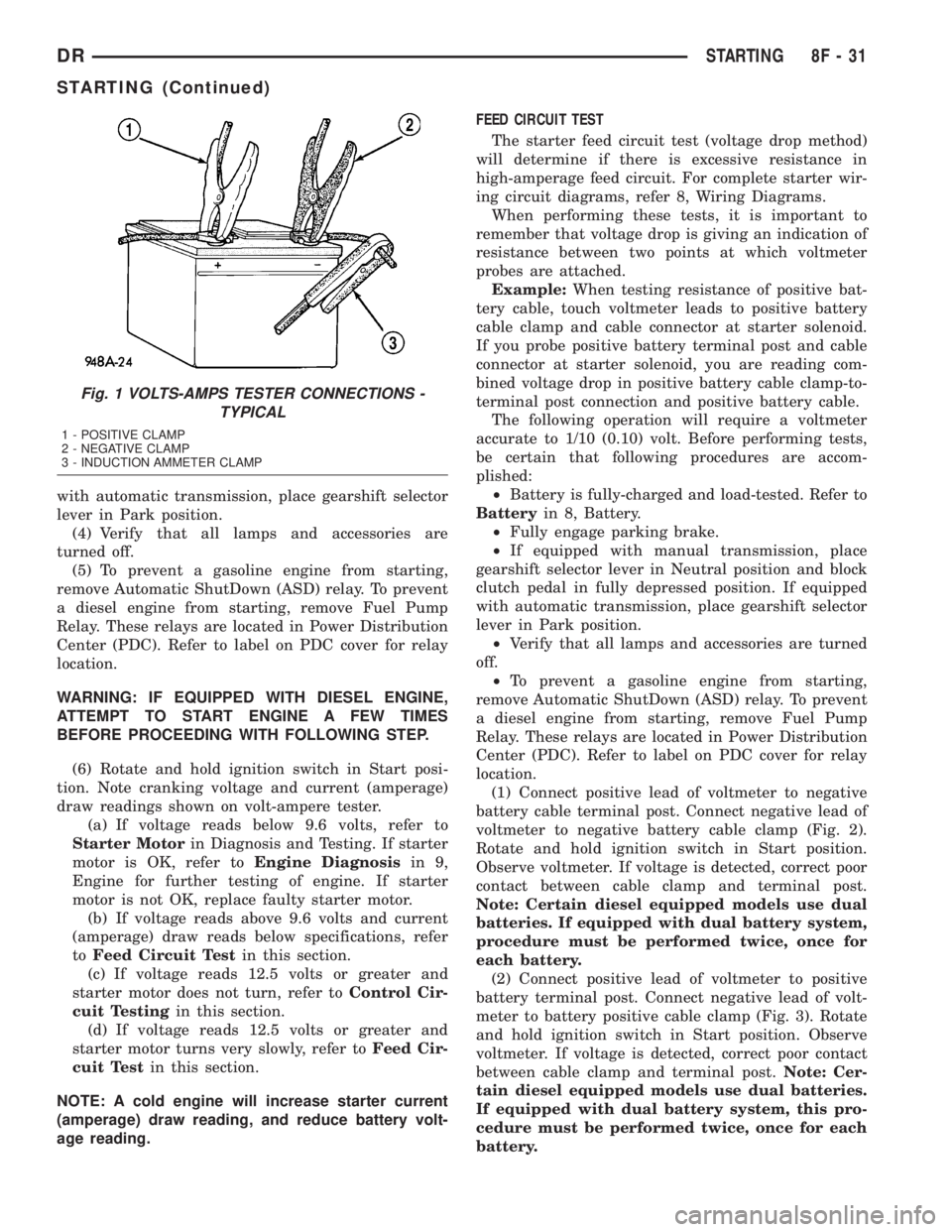
(1) Connect volt-ampere tester to battery terminals
(Fig. 1). See instructions provided by manufacturer of
volt-ampere tester being used.Note: Certain diesel
equipped models use dual batteries. If equipped
with dual battery system, tester should be con-
nected to battery on left side of vehicle only.
Also, tester current reading must be taken from
positive battery cable lead that connects to
starter motor.
(2) Fully engage parking brake.
(3) If equipped with manual transmission, place
gearshift selector lever in Neutral position and block
clutch pedal in fully depressed position. If equipped
8F - 30 STARTINGDR
STARTING (Continued)
Page 436 of 2895
with automatic transmission, place gearshift selector
lever in Park position.
(4) Verify that all lamps and accessories are
turned off.
(5) To prevent a gasoline engine from starting,
remove Automatic ShutDown (ASD) relay. To prevent
a diesel engine from starting, remove Fuel Pump
Relay. These relays are located in Power Distribution
Center (PDC). Refer to label on PDC cover for relay
location.
WARNING: IF EQUIPPED WITH DIESEL ENGINE,
ATTEMPT TO START ENGINE A FEW TIMES
BEFORE PROCEEDING WITH FOLLOWING STEP.
(6) Rotate and hold ignition switch in Start posi-
tion. Note cranking voltage and current (amperage)
draw readings shown on volt-ampere tester.
(a) If voltage reads below 9.6 volts, refer to
Starter Motorin Diagnosis and Testing. If starter
motor is OK, refer toEngine Diagnosisin 9,
Engine for further testing of engine. If starter
motor is not OK, replace faulty starter motor.
(b) If voltage reads above 9.6 volts and current
(amperage) draw reads below specifications, refer
toFeed Circuit Testin this section.
(c) If voltage reads 12.5 volts or greater and
starter motor does not turn, refer toControl Cir-
cuit Testingin this section.
(d) If voltage reads 12.5 volts or greater and
starter motor turns very slowly, refer toFeed Cir-
cuit Testin this section.
NOTE: A cold engine will increase starter current
(amperage) draw reading, and reduce battery volt-
age reading.FEED CIRCUIT TEST
The starter feed circuit test (voltage drop method)
will determine if there is excessive resistance in
high-amperage feed circuit. For complete starter wir-
ing circuit diagrams, refer 8, Wiring Diagrams.
When performing these tests, it is important to
remember that voltage drop is giving an indication of
resistance between two points at which voltmeter
probes are attached.
Example:When testing resistance of positive bat-
tery cable, touch voltmeter leads to positive battery
cable clamp and cable connector at starter solenoid.
If you probe positive battery terminal post and cable
connector at starter solenoid, you are reading com-
bined voltage drop in positive battery cable clamp-to-
terminal post connection and positive battery cable.
The following operation will require a voltmeter
accurate to 1/10 (0.10) volt. Before performing tests,
be certain that following procedures are accom-
plished:
²Battery is fully-charged and load-tested. Refer to
Batteryin 8, Battery.
²Fully engage parking brake.
²If equipped with manual transmission, place
gearshift selector lever in Neutral position and block
clutch pedal in fully depressed position. If equipped
with automatic transmission, place gearshift selector
lever in Park position.
²Verify that all lamps and accessories are turned
off.
²To prevent a gasoline engine from starting,
remove Automatic ShutDown (ASD) relay. To prevent
a diesel engine from starting, remove Fuel Pump
Relay. These relays are located in Power Distribution
Center (PDC). Refer to label on PDC cover for relay
location.
(1) Connect positive lead of voltmeter to negative
battery cable terminal post. Connect negative lead of
voltmeter to negative battery cable clamp (Fig. 2).
Rotate and hold ignition switch in Start position.
Observe voltmeter. If voltage is detected, correct poor
contact between cable clamp and terminal post.
Note: Certain diesel equipped models use dual
batteries. If equipped with dual battery system,
procedure must be performed twice, once for
each battery.
(2) Connect positive lead of voltmeter to positive
battery terminal post. Connect negative lead of volt-
meter to battery positive cable clamp (Fig. 3). Rotate
and hold ignition switch in Start position. Observe
voltmeter. If voltage is detected, correct poor contact
between cable clamp and terminal post.Note: Cer-
tain diesel equipped models use dual batteries.
If equipped with dual battery system, this pro-
cedure must be performed twice, once for each
battery.
Fig. 1 VOLTS-AMPS TESTER CONNECTIONS -
TYPICAL
1 - POSITIVE CLAMP
2 - NEGATIVE CLAMP
3 - INDUCTION AMMETER CLAMP
DRSTARTING 8F - 31
STARTING (Continued)
Page 447 of 2895

heated mirror switch is depressed and released a sec-
ond time during the same ignition cycle, the elec-
tronic control logic and timer circuitry will
automatically turn the heated mirror system off after
a programmed time interval of about five minutes.
The heated mirror system will be shut off automati-
cally if the ignition switch is turned to the Off or
Accessory positions. After the heated mirror system
is turned On, it can also be turned off manually by
depressing and releasing the heated mirror switch a
second time.
When the heated mirror system is turned On, the
heated mirror system control logic and timer cir-
cuitry energizes the heated mirror system indicator
lamp and the heated mirror relay. When energized,
the heated mirror relay supplies fused ignition
switch output (run/start) current from a fuse in the
JB to the outside mirror heating grids located behind
the mirror glass of each of the outside rear view mir-
rors. When energized, each of the outside mirror
heating grids produces enough heat to warm the
glass of the outside rear view mirrors.
DIAGNOSIS AND TESTING - HEATED MIRROR
SYSTEM
If only one of the outside mirror heating grids is
inoperative, perform continuity checks on the circuits
and heater grid for that mirror only. If both outside
mirror heating grids are inoperative, proceed with
the heated mirror system diagnosis as follows. (Refer
to Appropriate Wiring Information).
WARNING: ON VEHICLES EQUIPPED WITH AIR-
BAGS, DISABLE THE AIRBAG SYSTEM BEFORE
ATTEMPTING ANY STEERING WHEEL, STEERING
COLUMN, OR INSTRUMENT PANEL COMPONENT
DIAGNOSIS OR SERVICE. DISCONNECT AND ISO-
LATE THE BATTERY NEGATIVE (GROUND) CABLE,
THEN WAIT TWO MINUTES FOR THE AIRBAG SYS-
TEM CAPACITOR TO DISCHARGE BEFORE PER-
FORMING FURTHER DIAGNOSIS OR SERVICE. THIS
IS THE ONLY SURE WAY TO DISABLE THE AIRBAG
SYSTEM. FAILURE TO TAKE THE PROPER PRE-
CAUTIONS COULD RESULT IN ACCIDENTAL AIR-
BAG DEPLOYMENT AND POSSIBLE PERSONAL
INJURY.The operation of the heated mirror system can be
confirmed in one of the following manners:
1. Turn the ignition switch to the On position.
While monitoring the instrument panel voltmeter,
momentarily depress and release the heated mirror
switch. When the heated mirror system is turned On,
a distinct voltmeter needle deflection should be
noted.
2. Turn the ignition switch to the On position.
Momentarily depress and release the heated mirror
switch to turn the heated mirror system On. The
heated mirror operation can be checked by feeling
the outside rear view mirror glass. A distinct differ-
ence in temperature between the unheated and
heated mirror glass can be detected within three to
four minutes of system operation.
The above checks will confirm system operation.
Illumination of the heated mirror system indicator
lamp means that there is electrical current available
at the heated mirror relay, but does not confirm that
the electrical current is reaching the outside mirror
heating grids.
If the heated mirror system does not operate, the
problem should be isolated in the following manner:
(1) Confirm that the ignition switch is in the On
position.
(2) Check the fuses in the Power Distribution Cen-
ter (PDC) and in the Junction Block (JB). The fuses
must be tight in their receptacles and all electrical
connections must be secure.
When the above steps have been completed and
both outside mirror heating grids are still inopera-
tive, one or more of the following is faulty:
²Heated mirror switch, electronic control logic
and timer circuitry, and heated mirror relay.
²Heated mirror wire harness circuits or connec-
tors.
²Outside mirror heating grid (both mirror grids
would have to be faulty).
If turning On the heated mirror system produces a
severe voltmeter deflection or fuse failures, check for
a shorted circuit between the output of the heated
mirror relay and the outside mirror heating grids.
8G - 2 HEATED MIRRORSDR
HEATED MIRRORS (Continued)
Page 450 of 2895

Diagnostic logic is built into the heated seat mod-
ule to help the person trying to locate the problem by
the most efficient means possible. Anytime a problem
is suspected, locate the diagnosis and testing proce-
dure for the component in question and follow the
steps until the specific problem is located and
resolved. Once the problem is thought to be cor-
rected, verify correct system operation. If the heated
seat system is functioning correctly return the vehi-
cle to service.
If a problem could not be verified such as not find-
ing anything wrong when following the diagnostic
procedure, this is a good indication that a INTER-
MITTENT problem may be present. You must then
attempt to find the intermittent problem, such as
moving the heating element within the seat while
testing continuity or wiggling the wire harness's/elec-
trical connectors under the seat while testing conti-
nuity. Always, eliminate all other potential problems
before attempting to replace the heated seat module.
PRELIMINARY TEST
Refer toWiringfor the location of complete heated
seat system wiring diagrams. Before testing the indi-
vidual components in the heated seat system, per-
form the following preliminary checks:
WARNING: DISABLE THE AIRBAG SYSTEM
BEFORE ATTEMPTING ANY STEERING WHEEL,
STEERING COLUMN, OR INSTRUMENT PANEL
COMPONENT DIAGNOSIS OR SERVICE. DISCON-
NECT AND ISOLATE THE BATTERY NEGATIVE
CABLE, THEN WAIT TWO MINUTES FOR THE AIR-
BAG SYSTEM CAPACITOR TO DISCHARGE
BEFORE PERFORMING FURTHER DIAGNOSIS OR
SERVICE. THIS IS THE ONLY SURE WAY TO DIS-
ABLE THE AIRBAG SYSTEM. FAILURE TO TAKE
THE PROPER PRECAUTIONS COULD RESULT IN
ACCIDENTAL AIRBAG DEPLOYMENT AND POSSI-
BLE PERSONAL INJURY.
²If the heated seat switch back lighting and the
cluster illumination lamps do not illuminate with the
headlamps or park lamps turned On, refer to the
Instrument Clustersection of the service manual
for the location of cluster illumination lamp diagnosis
and testing procedures. If the heated seat switch
back lighting does not illuminate, but the cluster illu-
mination lamps do illuminate with the headlamps or
park lamps turned On, refer toDiagnosis and Test-
ing the Heated Seat Switchin this section for the
location of the heated seat switch diagnosis and test-
ing procedures.
²If a single LED indicator lamp for one heated
seat switch does not operate and the heated seat ele-
ments do heat, refer toDiagnosis and Testing theHeated Seat Switchin this section for heated seat
switch diagnosis and testing procedures.
²If both LED indicator lamps for a heated seat
switch operate, but the heated seat elements do not
heat, refer toDiagnosis and Testing the Heated
Seat Modulein Electronic Control Modules for
heated seat module diagnosis and testing procedures.
²If the indicator lamp on either heated seat
switch remains illuminated after the heated seat has
been turned Off, refer toDiagnosis and Testing
the Heated Seat Modulein Electronic Control
Modules for heated seat module diagnosis and test-
ing procedures.
HEATED SEAT ELEMENT
DESCRIPTION
Vehicles equipped with the optional heated seat
system have two sets of electrically operated heating
element grids located in each front seat, one set for
the seat cushion and the other set for the seat back.
Each of the heated seat element grids consists of a
single length of resistor wire that is routed in a zig-
zag pattern and captured between a covering and the
adhesive foam rubber backing. Short pigtail wires
with connectors (Fig. 2) are soldered to each end of
each resistor wire element grid, which connect all of
Fig. 2 Heating Element Installed on Seat Cushion
Foam
1 - SEAT BACK WIRE HARNESS
2 - HEATED SEAT WIRE HARNESS CONNECTOR
3 - HEATED SEAT CUSHION ELEMENT
DRHEATED SEAT SYSTEM 8G - 5
HEATED SEAT SYSTEM (Continued)
Page 453 of 2895
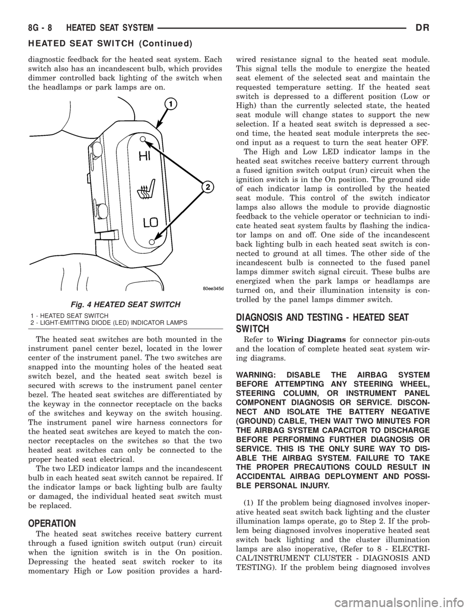
diagnostic feedback for the heated seat system. Each
switch also has an incandescent bulb, which provides
dimmer controlled back lighting of the switch when
the headlamps or park lamps are on.
The heated seat switches are both mounted in the
instrument panel center bezel, located in the lower
center of the instrument panel. The two switches are
snapped into the mounting holes of the heated seat
switch bezel, and the heated seat switch bezel is
secured with screws to the instrument panel center
bezel. The heated seat switches are differentiated by
the keyway in the connector receptacle on the backs
of the switches and keyway on the switch housing.
The instrument panel wire harness connectors for
the heated seat switches are keyed to match the con-
nector receptacles on the switches so that the two
heated seat switches can only be connected to the
proper heated seat electrical.
The two LED indicator lamps and the incandescent
bulb in each heated seat switch cannot be repaired. If
the indicator lamps or back lighting bulb are faulty
or damaged, the individual heated seat switch must
be replaced.
OPERATION
The heated seat switches receive battery current
through a fused ignition switch output (run) circuit
when the ignition switch is in the On position.
Depressing the heated seat switch rocker to its
momentary High or Low position provides a hard-wired resistance signal to the heated seat module.
This signal tells the module to energize the heated
seat element of the selected seat and maintain the
requested temperature setting. If the heated seat
switch is depressed to a different position (Low or
High) than the currently selected state, the heated
seat module will change states to support the new
selection. If a heated seat switch is depressed a sec-
ond time, the heated seat module interprets the sec-
ond input as a request to turn the seat heater OFF.
The High and Low LED indicator lamps in the
heated seat switches receive battery current through
a fused ignition switch output (run) circuit when the
ignition switch is in the On position. The ground side
of each indicator lamp is controlled by the heated
seat module. This control of the switch indicator
lamps also allows the module to provide diagnostic
feedback to the vehicle operator or technician to indi-
cate heated seat system faults by flashing the indica-
tor lamps on and off. One side of the incandescent
back lighting bulb in each heated seat switch is con-
nected to ground at all times. The other side of the
incandescent bulb is connected to the fused panel
lamps dimmer switch signal circuit. These bulbs are
energized when the park lamps or headlamps are
turned on, and their illumination intensity is con-
trolled by the panel lamps dimmer switch.
DIAGNOSIS AND TESTING - HEATED SEAT
SWITCH
Refer toWiring Diagramsfor connector pin-outs
and the location of complete heated seat system wir-
ing diagrams.
WARNING: DISABLE THE AIRBAG SYSTEM
BEFORE ATTEMPTING ANY STEERING WHEEL,
STEERING COLUMN, OR INSTRUMENT PANEL
COMPONENT DIAGNOSIS OR SERVICE. DISCON-
NECT AND ISOLATE THE BATTERY NEGATIVE
(GROUND) CABLE, THEN WAIT TWO MINUTES FOR
THE AIRBAG SYSTEM CAPACITOR TO DISCHARGE
BEFORE PERFORMING FURTHER DIAGNOSIS OR
SERVICE. THIS IS THE ONLY SURE WAY TO DIS-
ABLE THE AIRBAG SYSTEM. FAILURE TO TAKE
THE PROPER PRECAUTIONS COULD RESULT IN
ACCIDENTAL AIRBAG DEPLOYMENT AND POSSI-
BLE PERSONAL INJURY.
(1) If the problem being diagnosed involves inoper-
ative heated seat switch back lighting and the cluster
illumination lamps operate, go to Step 2. If the prob-
lem being diagnosed involves inoperative heated seat
switch back lighting and the cluster illumination
lamps are also inoperative, (Refer to 8 - ELECTRI-
CAL/INSTRUMENT CLUSTER - DIAGNOSIS AND
TESTING). If the problem being diagnosed involves
Fig. 4 HEATED SEAT SWITCH
1 - HEATED SEAT SWITCH
2 - LIGHT-EMITTING DIODE (LED) INDICATOR LAMPS
8G - 8 HEATED SEAT SYSTEMDR
HEATED SEAT SWITCH (Continued)
Page 456 of 2895
HORN
TABLE OF CONTENTS
page page
HORN SYSTEM
DESCRIPTION..........................1
OPERATION............................1
DIAGNOSIS AND TESTING - HORN SYSTEM . . . 1
HORN
DIAGNOSIS AND TESTING - HORN..........1REMOVAL.............................2
INSTALLATION..........................2
HORN SWITCH
DESCRIPTION..........................2
DIAGNOSIS AND TESTING - HORN SWITCH . . . 2
HORN SYSTEM
DESCRIPTION
The dual-note horn system features dual electro-
magnetic horn units. The horn system includes the
following major components:
²Horn- The two horns are located on the left
side of the engine compartment below the Integrated
Power Module (IPM).
²Horn Switch- The horn switch is molded into
the driver airbag trim cover.
OPERATION
The horn system operates on battery current
received through a fuse in the Integrated Power
Module (IPM). The horn system circuit is designed so
that the system will remain operational, regardless
of the ignition switch position.
DIAGNOSIS AND TESTING - HORN SYSTEM
The most reliable, efficient, and accurate
means to diagnose the horn system requires the
use of a DRBIIItscan tool and the proper Diag-
nostic Procedures manual. The DRBIIItscan
tool can provide confirmation that the PCI data
bus is functional, that all of the electronic mod-
ules are sending and receiving the proper mes-
sages on the PCI data bus, and that the horns
are being sent the proper hard wired outputs
for them to perform their functions.
Refer to the appropriate wiring information. The
wiring information includes wiring diagrams, proper
wire and connector repair procedures, details of wire
harness routing and retention, connector pin-out
information and location views for the various wire
harness connectors, splices and grounds.
In most cases, any problem involving continually
sounding horns can be quickly alleviated by removing
the horn fuse from the Integrated Power Module
(IPM).WARNING: DISABLE THE AIRBAG SYSTEM
BEFORE ATTEMPTING ANY STEERING WHEEL,
STEERING COLUMN, SEAT BELT TENSIONER, SIDE
AIRBAG, OR INSTRUMENT PANEL COMPONENT
DIAGNOSIS OR SERVICE. DISCONNECT AND ISO-
LATE THE BATTERY NEGATIVE (GROUND) CABLE,
THEN WAIT TWO MINUTES FOR THE AIRBAG SYS-
TEM CAPACITOR TO DISCHARGE BEFORE PER-
FORMING FURTHER DIAGNOSIS OR SERVICE. THIS
IS THE ONLY SURE WAY TO DISABLE THE AIRBAG
SYSTEM. FAILURE TO TAKE THE PROPER PRE-
CAUTIONS COULD RESULT IN ACCIDENTAL AIR-
BAG DEPLOYMENT AND POSSIBLE PERSONAL
INJURY.
HORN
DIAGNOSIS AND TESTING - HORN
The most reliable, efficient, and accurate
means to diagnose the horn system requires the
use of a DRBIIItscan tool and the proper Diag-
nostic Procedures manual. The DRBIIItscan
tool can provide confirmation that the PCI data
bus is functional, that all of the electronic mod-
ules are sending and receiving the proper mes-
sages on the PCI data bus, and that the horns
are being sent the proper hard wired outputs
for them to perform their functions.
Refer to the appropriate wiring information. The
wiring information includes wiring diagrams, proper
wire and connector repair procedures, details of wire
harness routing and retention, connector pin-out
information and location views for the various wire
harness connectors, splices and grounds.
DRHORN 8H - 1
Page 457 of 2895
WARNING: DISABLE THE AIRBAG SYSTEM
BEFORE ATTEMPTING ANY STEERING WHEEL,
STEERING COLUMN, SEAT BELT TENSIONER, SIDE
AIRBAG, OR INSTRUMENT PANEL COMPONENT
DIAGNOSIS OR SERVICE. DISCONNECT AND ISO-
LATE THE BATTERY NEGATIVE (GROUND) CABLE,
THEN WAIT TWO MINUTES FOR THE AIRBAG SYS-
TEM CAPACITOR TO DISCHARGE BEFORE PER-
FORMING FURTHER DIAGNOSIS OR SERVICE. THIS
IS THE ONLY SURE WAY TO DISABLE THE AIRBAG
SYSTEM. FAILURE TO TAKE THE PROPER PRE-
CAUTIONS COULD RESULT IN ACCIDENTAL AIR-
BAG DEPLOYMENT AND POSSIBLE PERSONAL
INJURY.
REMOVAL
(1) Disconnect and isolate the battery negative
cable.
(2) Disconnect the wire harness connectors from
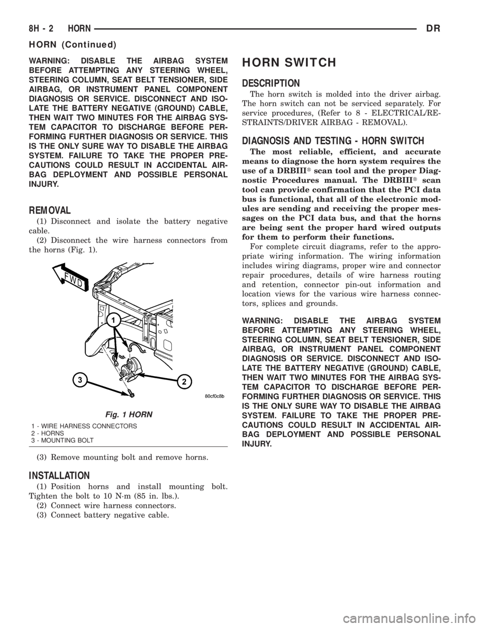
the horns (Fig. 1).
(3) Remove mounting bolt and remove horns.
INSTALLATION
(1) Position horns and install mounting bolt.
Tighten the bolt to 10 N´m (85 in. lbs.).
(2) Connect wire harness connectors.
(3) Connect battery negative cable.
HORN SWITCH
DESCRIPTION
The horn switch is molded into the driver airbag.
The horn switch can not be serviced separately. For
service procedures, (Refer to 8 - ELECTRICAL/RE-
STRAINTS/DRIVER AIRBAG - REMOVAL).
DIAGNOSIS AND TESTING - HORN SWITCH
The most reliable, efficient, and accurate
means to diagnose the horn system requires the
use of a DRBIIItscan tool and the proper Diag-
nostic Procedures manual. The DRBIIItscan
tool can provide confirmation that the PCI data
bus is functional, that all of the electronic mod-
ules are sending and receiving the proper mes-
sages on the PCI data bus, and that the horns
are being sent the proper hard wired outputs
for them to perform their functions.
For complete circuit diagrams, refer to the appro-
priate wiring information. The wiring information
includes wiring diagrams, proper wire and connector
repair procedures, details of wire harness routing
and retention, connector pin-out information and
location views for the various wire harness connec-
tors, splices and grounds.
WARNING: DISABLE THE AIRBAG SYSTEM
BEFORE ATTEMPTING ANY STEERING WHEEL,
STEERING COLUMN, SEAT BELT TENSIONER, SIDE
AIRBAG, OR INSTRUMENT PANEL COMPONENT
DIAGNOSIS OR SERVICE. DISCONNECT AND ISO-
LATE THE BATTERY NEGATIVE (GROUND) CABLE,
THEN WAIT TWO MINUTES FOR THE AIRBAG SYS-
TEM CAPACITOR TO DISCHARGE BEFORE PER-
FORMING FURTHER DIAGNOSIS OR SERVICE. THIS
IS THE ONLY SURE WAY TO DISABLE THE AIRBAG
SYSTEM. FAILURE TO TAKE THE PROPER PRE-
CAUTIONS COULD RESULT IN ACCIDENTAL AIR-
BAG DEPLOYMENT AND POSSIBLE PERSONAL
INJURY.
Fig. 1 HORN
1 - WIRE HARNESS CONNECTORS
2 - HORNS
3 - MOUNTING BOLT
8H - 2 HORNDR
HORN (Continued)
Page 464 of 2895
DIAGNOSIS AND TESTING - ASD AND FUEL
PUMP RELAYS
The following description of operation and
tests apply only to the Automatic Shutdown
(ASD) and fuel pump relays. The terminals on the
bottom of each relay are numbered. Two different
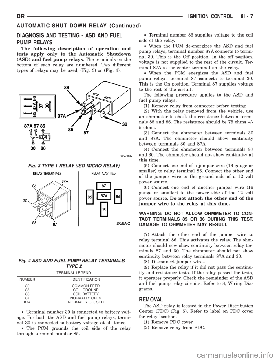
types of relays may be used, (Fig. 3) or (Fig. 4).
²Terminal number 30 is connected to battery volt-
age. For both the ASD and fuel pump relays, termi-
nal 30 is connected to battery voltage at all times.
²The PCM grounds the coil side of the relay
through terminal number 85.²Terminal number 86 supplies voltage to the coil
side of the relay.
²When the PCM de-energizes the ASD and fuel
pump relays, terminal number 87A connects to termi-
nal 30. This is the Off position. In the off position,
voltage is not supplied to the rest of the circuit. Ter-
minal 87A is the center terminal on the relay.
²When the PCM energizes the ASD and fuel
pump relays, terminal 87 connects to terminal 30.
This is the On position. Terminal 87 supplies voltage
to the rest of the circuit.
The following procedure applies to the ASD and
fuel pump relays.
(1) Remove relay from connector before testing.
(2) With the relay removed from the vehicle, use
an ohmmeter to check the resistance between termi-
nals 85 and 86. The resistance should be 75 ohms +/-
5 ohms.
(3) Connect the ohmmeter between terminals 30
and 87A. The ohmmeter should show continuity
between terminals 30 and 87A.
(4) Connect the ohmmeter between terminals 87
and 30. The ohmmeter should not show continuity at
this time.
(5) Connect one end of a jumper wire (16 gauge or
smaller) to relay terminal 85. Connect the other end
of the jumper wire to the ground side of a 12 volt
power source.
(6) Connect one end of another jumper wire (16
gauge or smaller) to the power side of the 12 volt
power source.Do not attach the other end of the
jumper wire to the relay at this time.
WARNING: DO NOT ALLOW OHMMETER TO CON-
TACT TERMINALS 85 OR 86 DURING THIS TEST.
DAMAGE TO OHMMETER MAY RESULT.
(7) Attach the other end of the jumper wire to
relay terminal 86. This activates the relay. The ohm-
meter should now show continuity between relay ter-
minals 87 and 30. The ohmmeter should not show
continuity between relay terminals 87A and 30.
(8) Disconnect jumper wires.
(9) Replace the relay if it did not pass the continu-
ity and resistance tests. If the relay passed the tests,
it operates properly. Check the remainder of the ASD
and fuel pump relay circuits. Refer to 8, Wiring Dia-
grams.
REMOVAL
The ASD relay is located in the Power Distribution
Center (PDC) (Fig. 5). Refer to label on PDC cover
for relay location.
(1) Remove PDC cover.
(2) Remove relay from PDC.
Fig. 3 TYPE 1 RELAY (ISO MICRO RELAY)
Fig. 4 ASD AND FUEL PUMP RELAY TERMINALSÐ
TYPE 2
TERMINAL LEGEND
NUMBER IDENTIFICATION
30 COMMON FEED
85 COIL GROUND
86 COIL BATTERY
87 NORMALLY OPEN
87A NORMALLY CLOSED
DRIGNITION CONTROL 8I - 7
AUTOMATIC SHUT DOWN RELAY (Continued)