2003 DODGE RAM remove seats
[x] Cancel search: remove seatsPage 2137 of 2895
CLEANING
Clean the valve housings, valves, plugs, springs,
and separator plates with a standard parts cleaning
solution only. Do not use gasoline, kerosene, or any
type of caustic solution.
Do not immerse any of the electrical components in
cleaning solution. Clean the governor solenoid and
sensor and the dual solenoid and harness assembly
by wiping them off with dry shop towels only.
Dry all except the electrical parts with compressed
air. Make sure all passages are clean and free from
obstructions.Do not use rags or shop towels to
dry or wipe off valve body components. Lint
from these materials can stick to valve body
parts, interfere with valve operation, and clog
filters and fluid passages.
Wipe the governor pressure sensor and solenoid
valve with dry, lint free shop towels only. The O-rings
on the sensor and solenoid valve are the only service-
able components. Be sure the vent ports in the sole-
noid valve are open and not blocked by dirt or debris.
Replace the valve and/or sensor only when DRB scan
tool diagnosis indicates this is necessary. Or, if either
part has sustained physical damage (dented,
deformed, broken, etc.).
CAUTION: Do not turn the small screw at the end of
the solenoid valve for any reason. Turning the
screw in either direction will ruin solenoid calibra-
tion and result in solenoid failure. In addition, thefilter on the solenoid valve is NOT serviceable. Do
not try to remove the filter as this will damage the
valve housing.
INSPECTION
Inspect the throttle and manual valve levers and
shafts. Do not attempt to straighten a bent shaft or
correct a loose lever. Replace these components if
worn, bent, loose or damaged in any way.
Inspect all of the valve body mating surfaces for
scratches, nicks, burrs, or distortion. Use a straight-
edge to check surface flatness. Minor scratches may
be removed with crocus cloth using only very light
pressure.
Minor distortion of a valve body mating surface
may be corrected by smoothing the surface with a
sheet of crocus cloth. Position the crocus cloth on a
surface plate, sheet of plate glass or equally flat sur-
face. If distortion is severe or any surfaces are
heavily scored, the valve body will have to be
replaced.
CAUTION: Many of the valves and plugs, such as
the throttle valve, shuttle valve plug, 1-2 shift valve
and 1-2 governor plug, are made of coated alumi-
num. Aluminum components are identified by the
dark color of the special coating applied to the sur-
face (or by testing with a magnet). Do not sand alu-
minum valves or plugs under any circumstances.
This practice could damage the special coating
causing the valves/plugs to stick and bind.
Inspect the valves and plugs for scratches, burrs,
nicks, or scores. Minor surface scratches on steel
valves and plugs can be removed with crocus cloth
butdo not round off the edges of the valve or
plug lands.Maintaining sharpness of these edges is
vitally important. The edges prevent foreign matter
from lodging between the valves and plugs and the
bore.
Inspect all the valve and plug bores in the valve
body. Use a penlight to view the bore interiors.
Replace the valve body if any bores are distorted or
scored. Inspect all of the valve body springs. The
springs must be free of distortion, warpage or broken
coils.
Check the two separator plates for distortion or
damage of any kind. Inspect the upper housing,
lower housing, 3-4 accumulator housing, and transfer
plate carefully. Be sure all fluid passages are clean
and clear. Check condition of the upper housing and
transfer plate check balls as well. The check balls
and ball seats must not be worn or damaged.
Trial fit each valve and plug in its bore to check
freedom of operation. When clean and dry, the valves
and plugs should drop freely into the bores.
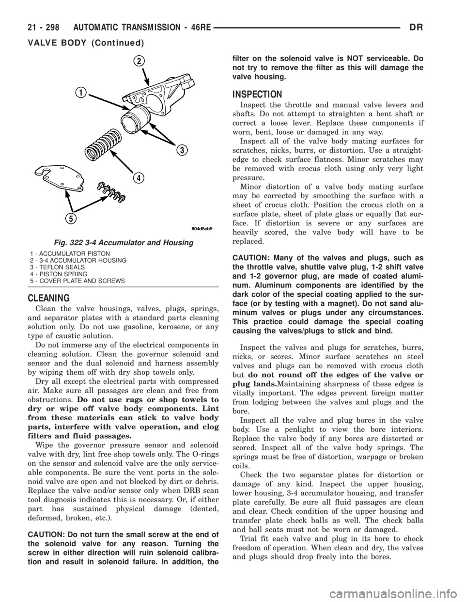
Fig. 322 3-4 Accumulator and Housing
1 - ACCUMULATOR PISTON
2 - 3-4 ACCUMULATOR HOUSING
3 - TEFLON SEALS
4 - PISTON SPRING
5 - COVER PLATE AND SCREWS
21 - 298 AUTOMATIC TRANSMISSION - 46REDR
VALVE BODY (Continued)
Page 2455 of 2895
EXTENSION HOUSING
BUSHING AND SEAL
REMOVAL
(1) Raise and support vehicle.
(2) Remove rear propeller shaft. (Refer to 3 - DIF-
FERENTIAL & DRIVELINE/PROPELLER SHAFT/
PROPELLER SHAFT - REMOVAL)
(3) Using a suitable pry tool or slide-hammer
mounted screw, remove the extension housing seal.
(4) Using Remover 8158, remove bushing from
extension housing.
INSTALLATION
(1) Clean fluid residue from sealing surface and
inspect for defects.
(2) Position replacement bushing in extension
housing with fluid port in bushing aligned with slot
in housing.
(3) Using Installer 8157, drive bushing into hous-
ing until installer seats against case.
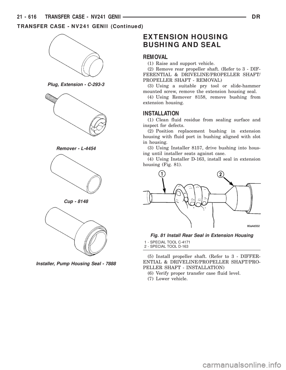
(4) Using Installer D-163, install seal in extension
housing (Fig. 81).
(5) Install propeller shaft. (Refer to 3 - DIFFER-
ENTIAL & DRIVELINE/PROPELLER SHAFT/PRO-
PELLER SHAFT - INSTALLATION)
(6) Verify proper transfer case fluid level.
(7) Lower vehicle.
Plug, Extension - C-293-3
Remover - L-4454
Cup - 8148
Installer, Pump Housing Seal - 7888
Fig. 81 Install Rear Seal in Extension Housing
1 - SPECIAL TOOL C-4171
2 - SPECIAL TOOL D-163
21 - 616 TRANSFER CASE - NV241 GENIIDR
TRANSFER CASE - NV241 GENII (Continued)
Page 2521 of 2895
EXTENSION HOUSING
BUSHING AND SEAL
REMOVAL
(1) Raise and support vehicle.
(2) Remove rear propeller shaft. (Refer to 3 - DIF-
FERENTIAL & DRIVELINE/PROPELLER SHAFT/
PROPELLER SHAFT - REMOVAL)
(3) Using a suitable pry tool or slide-hammer
mounted screw, remove the extension housing seal.
(4) Using Remover 8158, remove bushing from
extension housing.
INSTALLATION
(1) Clean fluid residue from sealing surface and
inspect for defects.
(2) Position replacement bushing in extension
housing with fluid port in bushing aligned with slot
in housing.
(3) Using Installer 8157, drive bushing into hous-
ing until installer seats against case.
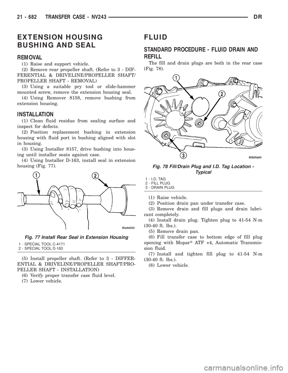
(4) Using Installer D-163, install seal in extension
housing (Fig. 77).
(5) Install propeller shaft. (Refer to 3 - DIFFER-
ENTIAL & DRIVELINE/PROPELLER SHAFT/PRO-
PELLER SHAFT - INSTALLATION)
(6) Verify proper transfer case fluid level.
(7) Lower vehicle.
FLUID
STANDARD PROCEDURE - FLUID DRAIN AND
REFILL
The fill and drain plugs are both in the rear case
(Fig. 78).
(1) Raise vehicle.
(2) Position drain pan under transfer case.
(3) Remove drain and fill plugs and drain lubri-
cant completely.
(4) Install drain plug. Tighten plug to 41-54 N´m
(30-40 ft. lbs.).
(5) Remove drain pan.
(6) Fill transfer case to bottom edge of fill plug
opening with MopartATF +4, Automatic Transmis-
sion fluid.
(7) Install and tighten fill plug to 41-54 N´m
(30-40 ft. lbs.).
(8) Lower vehicle.
Fig. 77 Install Rear Seal in Extension Housing
1 - SPECIAL TOOL C-4171
2 - SPECIAL TOOL D-163
Fig. 78 Fill/Drain Plug and I.D. Tag Location -
Typical
1 - I.D. TAG
2 - FILL PLUG
3 - DRAIN PLUG
21 - 682 TRANSFER CASE - NV243DR
Page 2576 of 2895
BODY
TABLE OF CONTENTS
page page
BODY
WARNING
SAFETY PRECAUTIONS AND WARNINGS . . . 1
DIAGNOSIS AND TESTING
DIAGNOSIS AND TESTING - WATER LEAKS . 1
DIAGNOSIS AND TESTING - WIND NOISE . . . 2
STANDARD PROCEDURE
STANDARD PROCEDURE - BODY
LUBRICATION.........................3
STANDARD PROCEDURE - HEAT STAKING . . 3
STANDARD PROCEDURE - PLASTIC BODY
PANEL REPAIR........................3
STANDARD PROCEDURE - BUZZ, SQUEAK
& RATTLE...........................11
SPECIFICATIONS - TORQUE..............12SPECIAL TOOLS
BODY..............................14
TAILGATE..............................15
DOOR - FRONT.........................18
DOORS - REAR.........................28
EXTERIOR.............................36
HOOD.................................46
INSTRUMENT PANEL.....................50
INTERIOR..............................63
PAINT.................................74
SEATS................................76
STATIONARY GLASS.....................86
WEATHERSTRIP/SEALS...................91
BODY STRUCTURE......................95
BODY
WARNING
SAFETY PRECAUTIONS AND WARNINGS
WARNING: USE AN OSHA APPROVED BREATHING
FILTER WHEN SPRAYING PAINT OR SOLVENTS IN
A CONFINED AREA. PERSONAL INJURY CAN
RESULT.
²AVOID PROLONGED SKIN CONTACT WITH
PETROLEUM OR ALCOHOL ± BASED CLEANING
SOLVENTS. PERSONAL INJURY CAN RESULT.
²DO NOT STAND UNDER A HOISTED VEHICLE
THAT IS NOT PROPERLY SUPPORTED ON SAFETY
STANDS. PERSONAL INJURY CAN RESULT.
CAUTION: When holes must be drilled or punched
in an inner body panel, verify depth of space to the
outer body panel, electrical wiring, or other compo-
nents. Damage to vehicle can result.
²Do not weld exterior panels unless combustible
material on the interior of vehicle is removed from
the repair area. Fire or hazardous conditions, can
result.
²Always have a fire extinguisher ready for use
when welding.
²Disconnect the negative (-) cable clamp from
the battery when servicing electrical components
that are live when the ignition is OFF. Damage to
electrical system can result.²Do not use abrasive chemicals or compounds
on painted surfaces. Damage to finish can result.
²Do not use harsh alkaline based cleaning sol-
vents on painted or upholstered surfaces. Damage
to finish or color can result.
²Do not hammer or pound on plastic trim panel
when servicing interior trim. Plastic panels can
break.
DIAGNOSIS AND TESTING
DIAGNOSIS AND TESTING - WATER LEAKS
Water leaks can be caused by poor sealing,
improper body component alignment, body seam
porosity, missing plugs, or blocked drain holes. Cen-
trifugal and gravitational force can cause water to
drip from a location away from the actual leak point,
making leak detection difficult. All body sealing
points should be water tight in normal wet-driving
conditions. Water flowing downward from the front of
the vehicle should not enter the passenger or luggage
compartment. Moving sealing surfaces will not
always seal water tight under all conditions. At
times, side glass or door seals will allow water to
enter the passenger compartment during high pres-
sure washing or hard driving rain (severe) condi-
tions. Overcompensating on door or glass
adjustments to stop a water leak that occurs under
severe conditions can cause premature seal wear and
excessive closing or latching effort. After completing
a repair, water test vehicle to verify leak has stopped
before returning vehicle to use.
DRBODY 23 - 1
Page 2619 of 2895
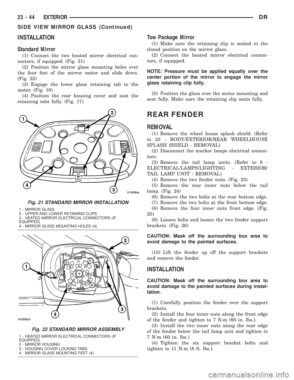
INSTALLATION
Standard Mirror
(1) Connect the two heated mirror electrical con-
nectors, if equipped. (Fig. 21)
(2) Position the mirror glass mounting holes over
the four feet of the mirror motor and slide down.
(Fig. 22)
(3) Engage the lower glass retaining tab to the
motor. (Fig. 18)
(4) Position the rear housing cover and seat the
retaining tabs fully. (Fig. 17)
Tow Package Mirror
(1) Make sure the retaining clip is seated in the
closed position on the mirror glass.
(2) Connect the heated mirror electrical connec-
tors, if equipped.
NOTE: Pressure must be applied equally over the
center portion of the mirror to engage the mirror
glass retaining clip fully.
(3) Position the glass over the motor mounting and
seat fully. Make sure the retaining clip seats fully.
REAR FENDER
REMOVAL
(1) Remove the wheel house splash shield. (Refer
to 23 - BODY/EXTERIOR/REAR WHEELHOUSE
SPLASH SHIELD - REMOVAL)
(2) Disconnect the marker lamps electrical connec-
tors.
(3) Remove the tail lamp units. (Refer to 8 -
ELECTRICAL/LAMPS/LIGHTING - EXTERIOR/
TAIL LAMP UNIT - REMOVAL)
(4) Remove the two fender nuts. (Fig. 23)
(5) Remove the rear inner nuts below the tail
lamp. (Fig. 24)
(6) Remove the two bolts at the rear bottom edge.
(7) Remove the two bolts at the front bottom edge.
(8) Remove the four inner nuts front edge. (Fig.
25)
(9) Loosen bolts and loosen the two fender support
brackets. (Fig. 26)
CAUTION: Mask off the surrounding box area to
avoid damage to the painted surfaces.
(10) Lift the fender up off the support brackets
and remove the fender.
INSTALLATION
CAUTION: Mask off the surrounding box area to
avoid damage to the painted surfaces during instal-
lation.
(1) Carefully position the fender over the support
brackets.
(2) Install the four inner nuts along the front edge
of the fender and tighten to 7 N´m (60 in. lbs.).
(3) Install the two inner nuts along the rear edge
of the fender below the tail lamp unit and tighten to
7 N´m (60 in. lbs.).
(4) Tighten the six support bracket bolts and
tighten to 11 N´m (8 ft. lbs.).
Fig. 21 STANDARD MIRROR INSTALLATION
1 - MIRROR GLASS
2 - UPPER AND LOWER RETAINING CLIPS
3 - HEATED MIRROR ELECTRICAL CONNECTORS (IF
EQUIPPED)
4 - MIRROR GLASS MOUNTING HOLES (4)
Fig. 22 STANDARD MIRROR ASSEMBLY
1 - HEATED MIRROR ELECTRICAL CONNECTORS (IF
EQUIPPED)
2 - MIRROR HOUSING
3 - HOUSING COVER LOCKING TABS
4 - MIRROR GLASS MOUNTING FEET (4)
23 - 44 EXTERIORDR
SIDE VIEW MIRROR GLASS (Continued)
Page 2641 of 2895
CARPETS AND FLOOR MATS
REMOVAL
(1) Remove the front seats. (Refer to 23 - BODY/
SEATS/SEAT - FRONT - REMOVAL)
(2) Remove the rear seats, if equipped. (Refer to 23
- BODY/SEATS/SEAT - REAR - REMOVAL)
(3) Remove the floor console, if equipped. (Refer to
23 - BODY/INTERIOR/FLOOR CONSOLE -
REMOVAL)
(4) Remove the lower b-pillar trim. (Refer to 23 -
BODY/INTERIOR/B-PILLAR LOWER TRIM -
REMOVAL)
(5) Using a trim stick C-4755 or equivalent,
remove the rear cup holder, if equipped.
(6) Remove the jack assembly.
(7) Remove the carpet.
INSTALLATION
(1) Install the carpet.
(2) Install the jack assembly.
(3) Install the rear cup holder, if equipped.
(4) Install the lower b-pillar trim. (Refer to 23 -
BODY/INTERIOR/B-PILLAR LOWER TRIM -
INSTALLATION)
(5) Install the floor console, if equipped. (Refer to
23 - BODY/INTERIOR/FLOOR CONSOLE - INSTAL-
LATION)
(6) Install the rear seats, if equipped. (Refer to 23
- BODY/SEATS/SEAT - REAR - INSTALLATION)
(7) Install the front seats. (Refer to 23 - BODY/
SEATS/SEAT - FRONT - INSTALLATION)
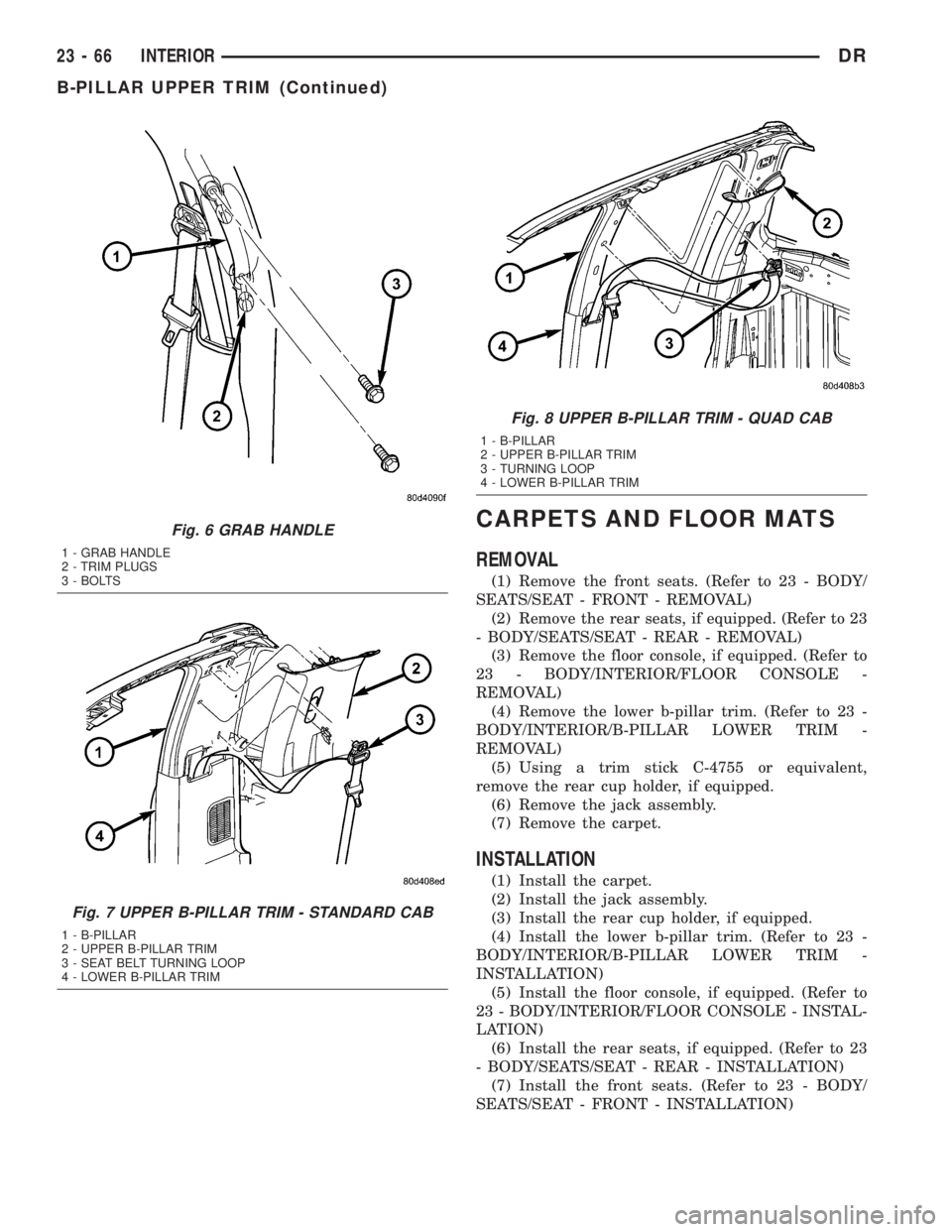
Fig. 6 GRAB HANDLE
1 - GRAB HANDLE
2 - TRIM PLUGS
3 - BOLTS
Fig. 7 UPPER B-PILLAR TRIM - STANDARD CAB
1 - B-PILLAR
2 - UPPER B-PILLAR TRIM
3 - SEAT BELT TURNING LOOP
4 - LOWER B-PILLAR TRIM
Fig. 8 UPPER B-PILLAR TRIM - QUAD CAB
1 - B-PILLAR
2 - UPPER B-PILLAR TRIM
3 - TURNING LOOP
4 - LOWER B-PILLAR TRIM
23 - 66 INTERIORDR
B-PILLAR UPPER TRIM (Continued)
Page 2642 of 2895
COAT HOOK
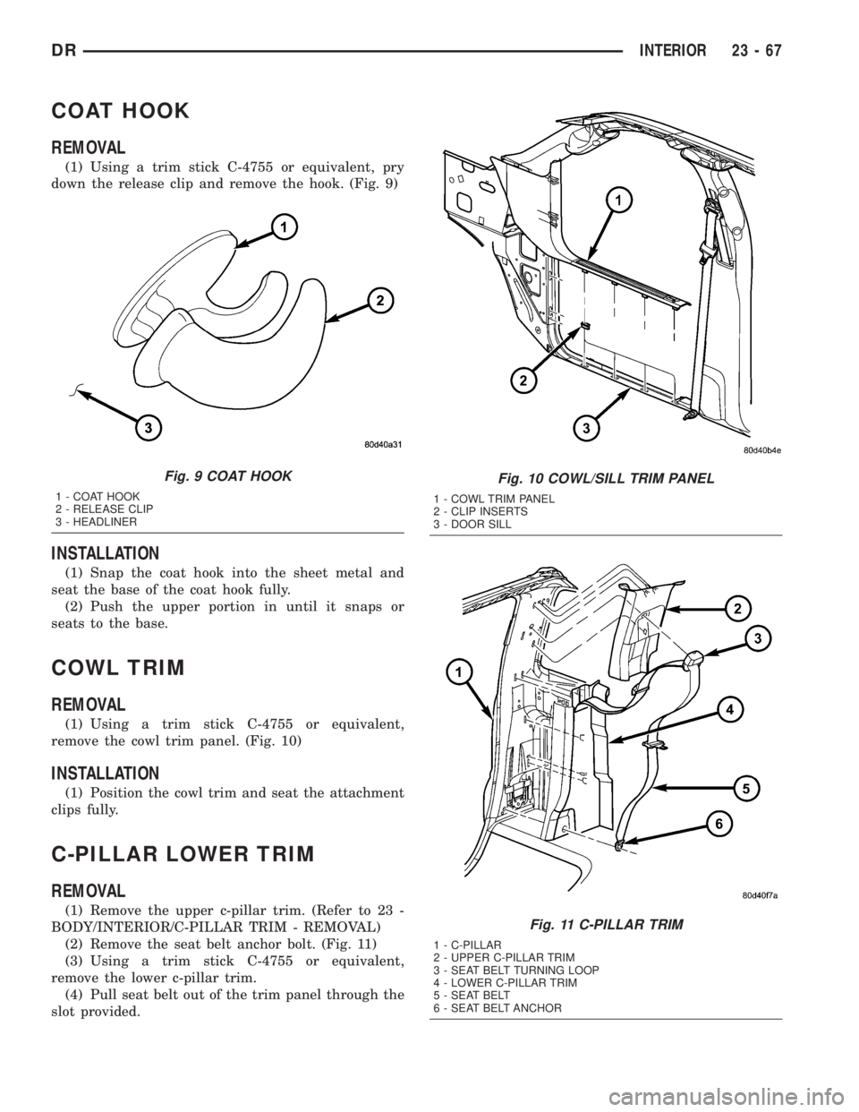
REMOVAL
(1) Using a trim stick C-4755 or equivalent, pry
down the release clip and remove the hook. (Fig. 9)
INSTALLATION
(1) Snap the coat hook into the sheet metal and
seat the base of the coat hook fully.
(2) Push the upper portion in until it snaps or
seats to the base.
COWL TRIM
REMOVAL
(1) Using a trim stick C-4755 or equivalent,
remove the cowl trim panel. (Fig. 10)
INSTALLATION
(1) Position the cowl trim and seat the attachment
clips fully.
C-PILLAR LOWER TRIM
REMOVAL
(1) Remove the upper c-pillar trim. (Refer to 23 -
BODY/INTERIOR/C-PILLAR TRIM - REMOVAL)
(2) Remove the seat belt anchor bolt. (Fig. 11)
(3) Using a trim stick C-4755 or equivalent,
remove the lower c-pillar trim.
(4) Pull seat belt out of the trim panel through the
slot provided.
Fig. 9 COAT HOOK
1 - COAT HOOK
2 - RELEASE CLIP
3 - HEADLINER
Fig. 10 COWL/SILL TRIM PANEL
1 - COWL TRIM PANEL
2 - CLIP INSERTS
3 - DOOR SILL
Fig. 11 C-PILLAR TRIM
1 - C-PILLAR
2 - UPPER C-PILLAR TRIM
3 - SEAT BELT TURNING LOOP
4 - LOWER C-PILLAR TRIM
5 - SEAT BELT
6 - SEAT BELT ANCHOR
DRINTERIOR 23 - 67
Page 2651 of 2895

SEATS
TABLE OF CONTENTS
page page
CENTER SEAT
REMOVAL.............................76
INSTALLATION.........................77
CENTER ARMREST / SEAT BACK
REMOVAL.............................77
INSTALLATION.........................78
CENTER SEAT BACK INERTIA HINGE COVER
REMOVAL.............................78
INSTALLATION.........................78
CENTER SEAT BACK HINGE
REMOVAL.............................79
INSTALLATION.........................80
CENTER SEAT BACK LID
REMOVAL.............................80
INSTALLATION.........................80
CENTER SEAT CUSHION
REMOVAL.............................80
INSTALLATION.........................80
CENTER SEAT CUSHION COVER
REMOVAL.............................81
INSTALLATION.........................81
UNDER SEAT STORAGE BIN
REMOVAL.............................81
INSTALLATION.........................81
UNDER SEAT STORAGE BIN COVERING
REMOVAL.............................81
INSTALLATION.........................81
UNDER SEAT STORAGE BIN LATCH
REMOVAL.............................81
INSTALLATION.........................81
HEADREST
REMOVAL.............................82
INSTALLATION.........................82
HEADREST SLEEVE
REMOVAL.............................82INSTALLATION.........................82
SEAT - FRONT
REMOVAL.............................82
INSTALLATION.........................82
SEAT BACK CUSHION / COVER - FRONT
REMOVAL.............................83
INSTALLATION.........................83
SEAT CUSHION / COVER - FRONT
REMOVAL.............................83
INSTALLATION.........................83
SEAT TRACK
REMOVAL.............................83
INSTALLATION.........................83
SEAT - REAR
REMOVAL.............................84
INSTALLATION.........................84
SEAT BACK - REAR
REMOVAL.............................84
INSTALLATION.........................84
SEAT BACK CUSHION / COVER - REAR
REMOVAL.............................85
INSTALLATION.........................85
SEAT CUSHION / COVER - REAR
REMOVAL.............................85
INSTALLATION.........................85
SEAT CUSHION FRAME - REAR
REMOVAL.............................85
INSTALLATION.........................85
SEAT BACK REAR - FOOTMANS LOOP
BRACKETS
REMOVAL.............................85
INSTALLATION.........................85
CENTER SEAT
REMOVAL
NOTE: Do not reuse the seat fasteners, always
replace with new ones.
(1) Remove and discard the front bolts. (Fig. 1)
(2) Position the seats forward, remove the rear
bolts and discard.
(3) Disconnect the 12v power supply electrical con-
nector, if equipped. (Fig. 2)(4) Fold the seat backs forward and roll the seat
assembly back in the vehicle.
(5) Remove the nuts attaching the center seat to
the drivers seat and the passenger seat and discard.
(Fig. 3)
(6) Roll the seat assembly forward and remove the
center seat portion.
23 - 76 SEATSDR